Download presentation
Presentation is loading. Please wait.

1
Principles of electrophysiology(His bundle,Mapping techniques)
")
2
History Equipment Catheter positions Basic electrophysiology study Mapping techniques Complications

3
History Sherlag et al-1968-His bundle electrogram
Durrer et al,Coumel et al-programmed electrical stimulation of heart Wellens et al-combined both techniques Josephson et al-endocardial catheter mapping of VT Huang et al,1985-radiofrequency catheter ablation

4
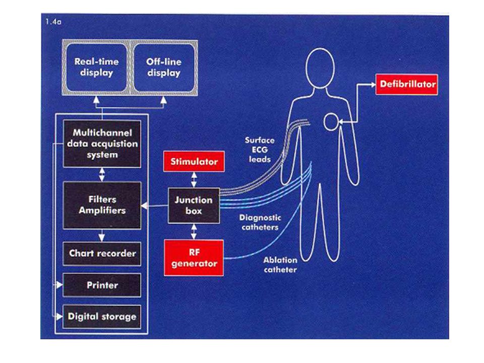
Equipment Flouroscopy Electrode catheters Junction box
Recording apparatus Stimulator Cardioverter/defibrillator

5
Electrode catheters Woven dacron catheters/polyurethane
Composed of thin wires attached to electrodes located at the tip and more proximal rings insulated by plastic Electrograms are usually recorded from two adjacent electrodes,electrode number is even Diagnostic catheters used in the atrium, His bundle, and ventricle are quadripolar (4 electrodes) Catheters used in the Coronary Sinus are usually decapolar Electrodes numbered from distal to proximal Distal electrodes used for pacing(in contact with endocardium) Preformed shapes-Josephson,Cournand
 Catheters used in the Coronary Sinus are usually decapolar. Electrodes numbered from distal to proximal. Distal electrodes used for pacing(in contact with endocardium) Preformed shapes-Josephson,Cournand.")
6
Cournand Josephson

7
Lasso catheter-pul.vein activation sequencing
Halo catheter-Rt.atrial activation sequencing

8
Inter electrode distance
May range from 1 mm to 10 mm Narrow inter electrode distance- precise timing of electrical activity compromise width of EGM and components of a multicomponent EGM 2mm or 5mm usual

9
Signal acquisition Unipolar Vs bipolar
Unipolar-only one electrode within heart;anode can be Wilson central terminal or another pole cm from the tip Bipolar-sum of unipolar signals from two intracardiac electrodes Unipolar – broad lower-amplitude signal Polarity &morphology of signal preserved important role during ablation Bipolar- More specific for local activity far field ventricular signal “cancels out”- effects of depolarization in a smaller region of tissue

12
Junction box Pairs of multiple pole switches
Matched for each recording and stimulation channel Permits ready selection of any pair of electrodes for stimulation or recording

13
Recording apparatus Recording systems record signals from all intracardiac electrodes that have been placed Signal processor-amplification and filtering split screen viewing, sweep speed changes and case tracking software Amplification Physiological signals< 10 mV Avoidance of extraneous signals at input of amplifier

14
Filtering High pass filters
Eliminate components below a particular frequency Surface ECG 0.05 Hz Preserve T wave Eliminate baseline drift Unipolar EGM-0.05 Hz Polarity &signal morphology important Bipolar EGM-30 to 50 Hz Timing of signal more important,not morphology

15
Low pass filters Notch filters
Eliminate components above a particular frequency To eliminate noise at higher frequencies ECG-100 to 200 Hz EGM- 500 Hz Notch filters Eliminate a particular frequency Usually to eliminate AC interference-50 Hz

16
0.05-400 Hz-low frequency components obscure others
High pass 30 Hz-ECG unacceptable ECG-0.05 to 200,EGM-30 to 500 Hz

17
Stimulator Stimulator is used to define pacing rates and protocols
Output is usually set at twice the diastolic treshold for a particular site Different modes Rapid pacing Single or multiple extrastimuli following a sensed beat Extra stimulus after a paced drive train

19
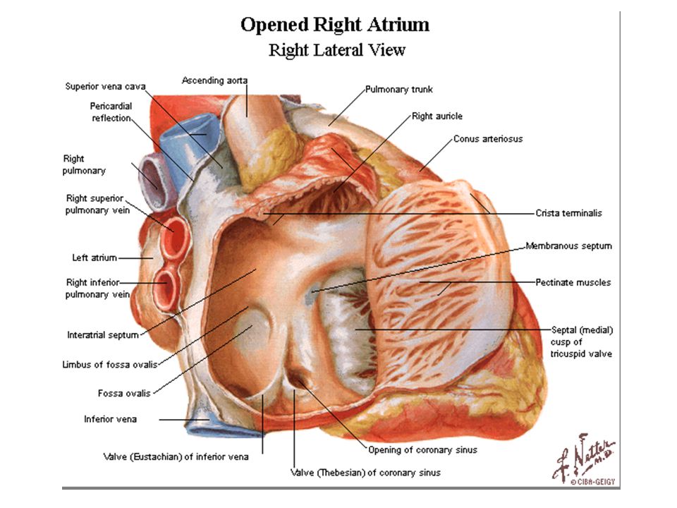
Catheter positions High RA RV apex His bundle
Quadripolar catheter,5mm spacing SVC/RA junction in posterolateral wall or RAA RV apex Quadripolar catheter 5 or 10 mm spacing His bundle Curved tip or steerable quadripolar;2mm spacing Placed in the region of His bundle, straddling RA&RV with catheter tip just past the tricuspid valve. Confirmed by HBE, with atrial and ventricular potentials approx.equal size and HB potentials seen b/w them

20
Coronary sinus Decapolar catheter with 2-8-2 spacing
Subclavian or jugular approach.femoral if steerable catheter available Catheter advanced until prox.pole over lateral border of spine in PA view EGM from LA and LV

23
RAO view

24
LAO view

25
Basic electrophysiology study
Signals are evaluated at faster sweep speeds:100 mm/second or higher Always look at simultaneous surface ECG Heart rate in bpm=60000/cycle length in ms

26
Measurement of basic intervals
PA interval Time interval from earliest atrial activation in the region of sinus node and atrial activation in the AV node region Measured as interval from earliest atrial activity(p onset in ECG or deflection in atrial electrogram) to earliest reproducible rapid deflection of atrial signal recorded in HB catheter 25-55 ms normal
 to earliest reproducible rapid deflection of atrial signal recorded in HB catheter ms normal.")
27
First atrial electrogram before the onset of the P wave in RA catheter
First atrial electrogram before the onset of the P wave in RA catheter.RA activation is complete when atrial signal recorded in His catheter. LA activation occurs after RA activation latest atrial signal recorded in distal CS(CS 1,2)
")
28
AH interval Time taken by the cardiac impulse to travel from low right atrium at IAS,over AV node,to the His bundle Measured from the earliest reproducible rapid deflection of atrial signal in electrogram recorded by His cather to the onset of His deflection(earliest deflection from baseline) in HBE ms considered normal Affected by autonomic tone
 in HBE ms considered normal. Affected by autonomic tone.")
29
HV interval Time taken for conduction from proximal His bundle to the ventricular myocardium Measured from the onset of His deflection in HBE to the earliest onset of ventricular activity recorded from multiple surface ECG leads or ventricular EGM in His bundle recording 35-55 ms normal.

31
Structures involved in basic interval measurement

32
Validation of His bundle potential
In sinus rhythm,apparent His deflection with H-V interval <30 ms- RBB potential or preexcitation Most proximal his bundle deflection a/w largest atrial electrogram Pace His bundle-if morphology similar to sinus rhythm ECG &stimulus to V interval identical to H-V interval in sinus rhythm His bundle deflection can be recorded in aorta from non coronary cusp and compared. Advancement of Lt.catheter to LV can record LBB potential.if coinciding with potential recorded from His catheter it is RBB potential

33
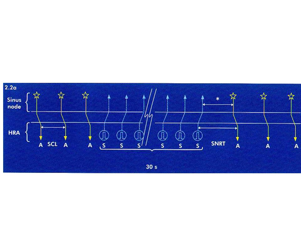
Tests of sinus node function
SNRT-sinus node recovery time Time taken by the sinus rhythm to resume after a period of overdrive atrial pacing(conventional 30 s) Defined as the interval measured in HRA from the last paced complex to first spontaneous complex after cessation of pacing Pacing at several cycle lengths done and longest values taken Normal<1500 Corrected SNRT- SNRT –basic sinus cycle length Normal<550 ms Total recovery time (TRT) interval b/w cessation of pacing and return to basic sinus cycle length Normal <5s
 Defined as the interval measured in HRA from the last paced complex to first spontaneous complex after cessation of pacing. Pacing at several cycle lengths done and longest values taken. Normal<1500. Corrected SNRT- SNRT –basic sinus cycle length. Normal<550 ms. Total recovery time (TRT) interval b/w cessation of pacing and return to basic sinus cycle length. Normal <5s.")
36
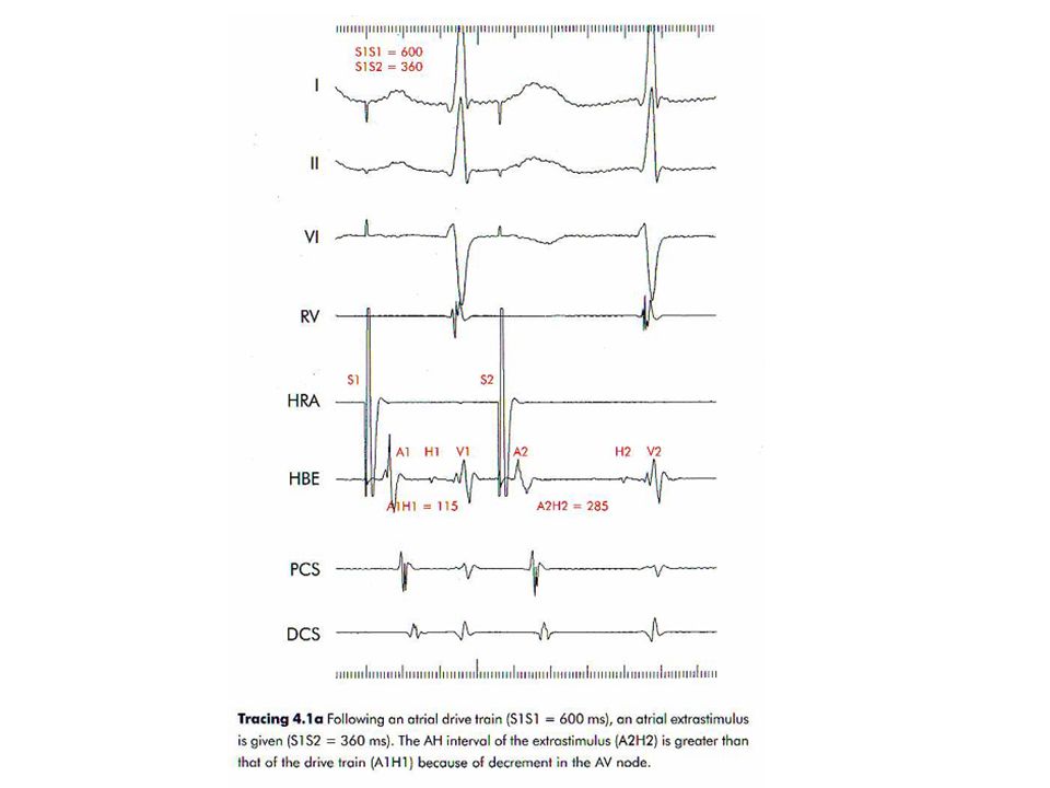
Atrial extrastimulus testing
Drivetrain of 8 paced beats at a fixed cycle length f/b an extrastimulus at same site Drive train is repeated while coupling interval of extrastimulus decreased progressively until atria no longer captured. Uses Refractory periods Dual AV nodal physiology Presence of accessory pathways Arrhythmia induction

37
Concept of refractoriness
Extrastimulus is more closely coupled-first a subnormal phase 0 upstroke occurs (relative refractoriness) –less Na+ channels available Extrastimulus does not produce a phase 0 upstroke (absolute refractoriness)-no Na+channel available for activation
 –less Na+ channels available. Extrastimulus does not produce a phase 0. upstroke (absolute refractoriness)-no Na+channel available for activation.")
38
RRP-longest coupling interval of a premature impulse that result in prolonged conduction of premature impulse compared to basic drive ERP- longest coupling interval of a premature impulse that fails to propagate through the tissue FRP-minimum interval b/w two consecutively conducted impulses through the tissue Determination of ERP of a tissue requires that FRP of proximal tissue should be less than that

39
AVNRRP- longest A1A2 at A2H2 prolongation-380ms
AVNFRP-shortest H1H2 interval-370ms AVNERP-longest A1A2 not conducted-280ms

40
S1 –S2 380 ms. slight prolongation of A-H interval. H-V remain same
S1 –S2 380 ms.slight prolongation of A-H interval.H-V remain same.pattern of activation in CS electrogram is different.

41
S1-S2 320 ms.atrial electrogram with no His potential recording.
AVNERP-A1-A2 interval 330 ms. S2-A2>S1-A1 interval-atrial RRP

42
S1-S2 280 ms.no atrial capture-atrial ERP

43
AVNERP cannot be calculated by this method if FRP of atria longer than ERP of AV node
Earlier coupling intervals decrease refractoriness.multiple extrastimuli given-first one conditions atrial tissue to shorten refractory period so that a second closely coupled stimulus can be used to measure AVNERP

44
Atrial refractory period reached at 260 ms before AVN refractoriness could be calculated

45
In order to evaluate the properties of the AV node in the same patient, two atrial
extrastimuli are delivered.First (S2) with a coupling interval of 280 ms and the second (S3) at 220 ms(S2 S3 interval gradually decreased until blocked).No conduction through the AV node a/w S3.AVNERP can now be calculated at 220 ms.
 with a coupling interval of 280 ms and the second (S3) at 220 ms(S2 S3 interval gradually decreased until blocked).No conduction through the AV node a/w S3.AVNERP can now be calculated at 220 ms.")
46
Dual AV node physiology
An increase in the AH interval ≥50 ms caused by a decrease in the coupling interval of an atrial extrastimulus by 10 ms ERP of fast pathway has reached and conduction over the AV node has shifted from the usual fast pathway to a slow pathway Dual AV nodal physiology can be inferred from discontinuity in antegrade conduction curve of AV node More than one discontinuity suggest presence of multiple AV nodal pathways

51
Gap phenomenon Conduction of an impulse may be blocked at a certain S1S2 interval and reappear at a lower S1S2 interval Impulse conducted over two structures in sequence first having a shorter ERP Delay in proximal structure causes the impulse to arrive at second structure with an increased coupling interval

54
Incremental atrial pacing
Incremental pacing (e.g. in the atrium) begins at a stable cycle length slightly below that of the sinus rhythm pacing cycle length is then shortened by 10 to 50 ms, a few beats are observed at the new pacing cycle length and the cycle length is again decreased by the same amount. AH interval increases due to decremental conduction property of the AV node(depolarisation due to slow inward Ca2+ current). HV interval and the QRS complex remain same(depolarisation due to fast inward Na+channel)
 begins at a stable cycle length slightly below that of the sinus rhythm. pacing cycle length is then shortened by 10. to 50 ms, a few beats are observed at the new pacing cycle length and the cycle length is again decreased by the same amount. AH interval increases due to decremental conduction property of the AV node(depolarisation due to slow inward Ca2+ current). HV interval and the QRS complex remain same(depolarisation due to fast inward Na+channel)")
55
Atrial pacing at 600 ms-

56
Cycle length 450 ms.AH prolongation.1:1 A-V relation

57
Cycle length 350 ms.A V relation not 1:1.AVBCL reached

58
Cycle length at which the atrial:ventricular relationship is no longer 1:1 is called atrioventricular blocked cycle length or AVBCL AVBCL provides information on the robustness of atrioventricular conduction. Devt. of AV Wenckebach block at rapid paced rates is normal.AV block at slow paced rates suggests the presence of AV nodal disease

59
Ventricular extrastimulus testing
V A conduction can be demonstrated in majority either at rest or by using isoproterenol Earliest part of atria depolarised is near AV node-so earliest atrial activation in His catheter f/b CS from proximal to distal f/b HRA This sequence –concentric atrial activation During antegrade conduction (atrial pacing) decremental response occurs mainly in AV node. During retrograde conduction (ventricular pacing), the decremental conduction can occur in two different structures: the His-Purkinje system and/or the AV node
 decremental response occurs mainly in AV node. During retrograde conduction (ventricular pacing), the decremental conduction can occur in two different structures: the His-Purkinje system and/or the AV node.")
60
S1S2 600ms.retrograde atrial activation

61
VAERP 580 ms

62
BB reentry a/w ventricular extra.His deflection occurs prior to this

63
premature ventricular extrastimulus blocks retrogradely in RBB,but depolarization travels slowly across IVS and up the LBB. It reenters the right bundle and leads to an additional QRS Complex of LBBB morphology

64
Incremental ventricular pacing –VABCL can be measured
Cycle length at which 1:1 VA relation disappear is VABCL

66
Mapping Mapping is used to localise site of origin of abnormal beats or to identify the tachycardia circuit in case of Reentrant arrhythmias Mapping procedures Activation Sequence Mapping Voltage mapping( Substrate / Fractionated electrogram ) Pace Mapping Entrainment Mapping Miscellaneous
 Pace Mapping. Entrainment Mapping. Miscellaneous.")
67
Pace mapping Manipulation of mapping catheter to region of origin of tachycardia Pace at this site at same cycle length as tachycardia Greater the concordance b/w tachycardia and morphology during pacing-closer exit site Look for 12/12 match More useful in ventricular tachycardia as QRS morphology is easier to compare Allows to home in on the region of interest,cannot pinpoint site for ablation Does not require tachycardia to sustain over a longer time

68
Pace Map 12/12 Match

69
Activation sequence mapping
Required to pinpoint focus of tachycardia During tachycardia mapping catheter explores the endocardium to identify the site where earliest electrogram relative to a fixed reference is recorded. Suitable site Local electrogram precedes any other activity One from which any movement results in a later electrogram One at which unipolar electrogram shows a sharp initial negative deflection

71
Entrainment mapping Allows confirmation of Reentry
Allows localisation of circuit and isthmus Entrainment is a continous resetting of a reentrant circuit by a series of stimuli

72
Criteria for entrainment
Constant fusion during constant overdrive pacing,last paced beat entrained not fused Progressive fusion during overdrive pacing as pacing rate increases Localised conduction block to a site for one paced beat a/w interruption of the tachycardia ,followed by activation of that site by next paced beat from a different direction and with a shorter conduction time During pacing at two different rates during a tachycardia,there is change in conduction time to and EMG morphology at a recording site

73
Entrainment results in a fusion complex
Pacing stopped-last one entrained but goes round the circuit-morphology similar to original rhythm

74
If pacing CL progressively shortened circuit is invaded to a greater extent-fusion increases

75
A premature paced beat collides with head and tail-fails to propagate
Next beat is purely paced and R is activated from a different direction

76
Manifest entrainment-demonstration of resetting with fusion
Cocealed entrainment-failure to demonstrate fusion but PPI equal to tachycardia cycle length.site protected isthmus PPI equal to TCL (within ms)if pacing site within reentrant circuit Post pacing interval-interval b/w last pacing stimulus that entrained the tachycardia and the next recorded EGM at the pacing site
if pacing site within reentrant circuit. Post pacing interval-interval b/w last pacing stimulus that entrained the tachycardia and the next recorded EGM at the pacing site.")
78
Manifest Entrainment with Fusion
Premature impulse invade tachycardia circuit.In antidromic direction it collides and extinguishes reentrant wavefront.In orthodromic direction it creates a new wavefront(resets).
.")
79
Concealed Fusion Antidromic wave front does not contribute much to the morphology of tachycardia beat Area of slow conduction : Isthmus

80
Concealed Fusion Post Pacing Interval If paced from the critical Isthmus PPI = TCL

82
Substrate( Volatage) Mapping
Scarred Myocardium has Low Voltage 0.5 mV or Less : Dense Scar 0.5 – 1.5 mV : Borderline Zone > 1.5 mv : Normal area

83
Advanced mapping systems
Electroanatomic mapping-CARTO system Metal coil placed in a magnetic field Catheter contains a location sensor in tip A 3D map is created by placing catheter in known anatomic positions Local electrogram at each point superimposed on anatomical map to give a color coded activation map

85
Non contact mapping-ENSITE
Multi electrode array probe with 64 non contact electrodes Endocardial boundaries defined with a conventional mapping catheter 3D endocardial potential map is created from a single cardiac cycle Magnetic navigation system Ablation catheter can be guided and positioned by magnetic fields to a desired site within cardiac chamber

86
Complications Vascular complications Pneumothorax Cardiac tamponade
AV node damage requiring PPI Arrhythmia induction Thromboembolic complication Pulmonary vein stenosis

87
Thank you

Similar presentations


>")


 n Generated in the heart n amplitude range: 0.5 - 4 mV n frequency.>")

