Download presentation
Presentation is loading. Please wait.

1
MANUFACTURING PROCESS
AMMONIA MANUFACTURING PROCESS

2
History Early in the twentieth century, several chemists tried to make ammonia from atmospheric nitrogen. German chemist Fritz Haber discovered a process that is still used today. Robert Le Rossignol was instrumental in the development of the high-pressure devices used in the Haber process. They demonstrated their process in the summer of 1909 by producing ammonia from air drop by drop, at the rate of about 125 ml per hour. The process was purchased by the German chemical company BASF, which assigned Carl Bosch the task of scaling up Haber's tabletop machine to industrial-level production.

3
History He succeeded in this process in Haber and Bosch were later awarded Nobel prizes, in 1918 and 1931 respectively, for their work in overcoming the chemical and engineering problems posed by the use of large-scale, continuous-flow, high-pressure technology. Ammonia was first manufactured using the Haber process on an industrial scale in 1913 in BASF's plant in Germany, production reaching 20 tonnes/day the following year. During World War I, the synthetic ammonia was used for the production of nitric acid.

5
Manufacturing Process
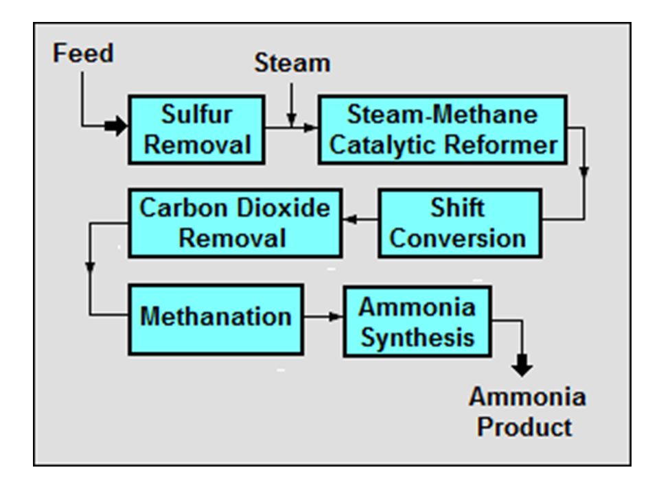
Synthetic Ammonia (NH3) Synthetic ammonia, from natural gas, is produced by reacting hydrogen with nitrogen. Six processing steps are required to produce synthetic ammonia using the catalytic steam reforming method as follows:
 Synthetic ammonia, from natural gas, is produced by reacting hydrogen with nitrogen. Six processing steps are required to produce synthetic ammonia using the catalytic steam reforming method as follows:")
6
Natural gas desulfurization
In this operation, the sulfur content (mainly as H2S) is reduced to below 280 micrograms/ m3 to prevent poisoning of the catalyst used in steam reforming step. Desulfurization takes place by adsorption of H2S gas on the surface of zinc oxide or active carbon. The adsorbent is reactivated by stripping with super heated steam. The feed gas is preheated to o C and then treated in a desulphurisation vessel where the sulphur compounds are hydrogenated to H2S using cobalt molybdenum catalyst (CoO and MgO3) and then adsorbed on palletized zinc oxide.
 is reduced to below 280 micrograms/ m3 to prevent poisoning of the catalyst used in steam reforming step. Desulfurization takes place by adsorption of H2S gas on the surface of zinc oxide or active carbon. The adsorbent is reactivated by stripping with super heated steam. The feed gas is preheated to o C and then treated in a desulphurisation vessel where the sulphur compounds are hydrogenated to H2S using cobalt molybdenum catalyst (CoO and MgO3) and then adsorbed on palletized zinc oxide.")
7
2. Catalytic steam reforming
The desulfurized natural gas is preheated by mixing with superheated steam (to o C) then enters the primary reformer and passes over the Ni catalyst where it is converted to hydrogen, CO and CO2 according to the following equation: Ni o C CH4 + H2O CO + 3H2 CO + H2O CO2 + H2
 then enters the primary reformer and passes over the Ni catalyst where it is converted to hydrogen, CO and CO2 according to the following equation: Ni o C CH4 + H2O CO + 3H2. CO + H2O CO2 + H2.")
8
The reaction is highly endothermic and additional heat is required to raise the temperature to o C at the reformer outlet. Only % of the methane feed is reformed in the primary reformer. The gas from the primary reformer is then sent to the secondary reformer, where it is mixed with compressed hot air at around 600o C and passed over nickel catalyst.

9
Sufficient air is added to produce a final synthesis gas having a hydrogen to nitrogen mole ratio of three to one. The gas leaving the secondary reformer (H2, N2, CO, CO2 and H2O) is cooled to 360ºC in a waste heat boiler before being sent to carbon monoxide shift. Ni Catalyst 900 – 1200o C CH4 + ½ O2 + 2N2 → CO + 2H2 + 2N2

10
3. Carbon monoxide shift After cooling, the gas, which contains % CO dry gas base, enters high temperature CO shift converter ( ºC) where CO converts to CO2 using iron oxide catalyst and chromium oxide initiator. The following reaction takes place: CO + H2O → CO2 + H2
 where CO converts to CO2 using iron oxide catalyst and chromium oxide initiator. The following reaction takes place: CO + H2O → CO2 + H2.")
11
The exit gas is then cooled in a heat exchanger before being sent to a low temperature shift converter, where CO is converted to CO2 by a copper oxide/ zinc oxide catalyst. The residual CO content in the converter gas is about % (dry gas base) CO content is important for the efficiency of the process.
 CO content is important for the efficiency of the process..")
12
4. Carbon dioxide removal
The gas from the shift is cooled from 210 to 110º C and steam is condensed and separated from the gas. The shift gas is purified from CO2 in a chemical or a physical absorption process. The solvents used in chemical absorption are mainly aqueous amine solutions (Mono Ethanolamine (MEA), Di Ethanolamine (aMDEA) or hot potassium carbonate solutions. Physical solvents are glycol dimethylethers, propylene carbonate and others. V2O5 is used as a corrosion inhibitor.
, Di Ethanolamine (aMDEA) or hot potassium carbonate solutions. Physical solvents are glycol dimethylethers, propylene carbonate and others. V2O5 is used as a corrosion inhibitor.")
13
The condensed steam contains ammonia and methanol, and small amount of amines, formic acid, acetic acid, sodium, iron, copper, zinc, aluminum and calcium. This condensate is sent to the stripper. Trace metals remaining in the process condensate can be removed in waste water treatment plant by ion exchange. The solvent is regenerated by preheating and steam stripping.

14
5. Methanation Residual CO2 and CO, in the synthesis gas, must be removed by catalytic methanation by using Ni catalyst at ºC according to the following reaction: CO2 + H2 → CO + H2O CO + 3H2 → CH4 + H2O Methane is an inert gas with respect to ammonia catalyst, while CO2 and CO can poison the catalyst.

15
6. Ammonia Synthesis Exit gas from the methanator is almost a pure. Three to one mole ratio of hydrogen to nitrogen is converted to ammonia according to the following reaction N2 + 3H2 → 2NH3 First the gas is compressed from 30 atm to a pressure 200 atm, heated against exit gas from converter and entered the converter containing iron promoted catalyst.

16
This results in a portion of the gas being converted to ammonia (15 %), which is condensed and separated in a liquid vapor separator and sent to a let-down separator. The unconverted synthesis gas is further compressed and heated to 180ºC before entering the converter containing an iron oxide catalyst. A newly developed ammonia synthesis catalyst containing ruthenium on a graphite support has a much higher activity per unit of volume and has a potential to increase conversion and lower operating pressures.

17
Ammonia gas from the converter is condensed and separated then sent to the let-down separator where a small portion of the overhead gas is purged to prevent buildup of inert gases such as argon in the circulating gas system. Ammonia is flashed to get rid of dissolved gas. These gases are scrubbed to remove the traces of NH3 in the form of ammonium hydroxide and the gases are used as part of the primary reformer fuel. The liquid ammonia can be either stored in pressure storage or in atmospheric double insulated refrigerated tank.

18
NH3 Process Flow Diagram

19
Devices and equipment:
1-compressors; 2-preheaters; 3-hydrogenation reactor; 4-adsorber to remove H2S; 5-tube furnace; 6- converter; 7-steam boilers; 8-converters of CO; 9-absorber of CO2; 10-reboiler;

20
11-regenerator of monoethanolamine solution;
12-pump; 13- hydrogenation vessel of residual CO and CO2; 14-air-cooled heat exchangers; 15-condensation column; 16-evaporator of liquid NH3; 17- ammonia converter; 18-water heater; 19-heat exchanger; 20-separator.

Similar presentations


 燃料脫硫 (fuel desulfurization, removal of sulfur from fuel) 排煙脫硫 (flue gas desulfurization, FGD)>")
 is made by reacting together nitrogen and hydrogen. (a) What is the source of the (i)>")

 Ammonia (NH 3 ) is an important compound of nitrogen and hydrogen. It is produced by the natural decomposition of animal and vegetable.>")


 NITRIC ACID PRODUCTION 1-INTRODUCTION.>")
 The Haber Process & The Ostwald Process 1.>")
