Download presentation
Presentation is loading. Please wait.

1
CFD Simulations of a Novel “Squirt-Nozzle and Water Bath” Cooling System for the RFQ

2
Vacuum Pump Flange Vacuum Flange Coolant Manifold Water Baths Milled Into Vanes Potentially Bolted Together Tuner & Coupler Ports Vanes

3
Vane Cut-Back Vane End Water Bath Shaped to Follow Vane Cut-Back Tuner & Coupler Ports O-Ring Joint to Mount to End Wall

4
Temperature vs. Input Power Outer WallVane Tip

5
Total Heat Load on Walls = 1 MW Water-bath Heat Transfer Coefficient = 3000 W m -2 K -1 Thermal Solver Solution Temperature / °C Really need to directly cool the vane tips!

6
Squirt Nozzles

7
Squirt Nozzle Inserted Squirt Nozzle HTC: 0 Wm -2 K -1 Input Power: 500 kW

8
Squirt Nozzle Inserted Squirt Nozzle HTC: 1000 Wm -2 K -1 Input Power: 500 kW

9
Squirt Nozzle Inserted Squirt Nozzle HTC: 2000 Wm -2 K -1 Input Power: 500 kW

10
Squirt Nozzle Inserted Squirt Nozzle HTC: 3000 Wm -2 K -1 Input Power: 500 kW

11
Squirt Nozzle Inserted Squirt Nozzle HTC: 4000 Wm -2 K -1 Input Power: 500 kW

12
Squirt Nozzle Inserted Squirt Nozzle HTC: 5000 Wm -2 K -1 Input Power: 500 kW

13
Squirt Nozzle Inserted Squirt Nozzle HTC: 7500 Wm -2 K -1 Input Power: 500 kW

14
Squirt Nozzle Inserted Squirt Nozzle HTC: 10000 Wm -2 K -1 Input Power: 500 kW

15
Water bath HTC: 1000 Wm -2 K -1 Tuner, Coupler & Vacuum Port HTC: 3000 Wm -2 K -1 Input Power: 500 kW Variation with Squirt Nozzle HTC

16
Are these HTCs Achievable? Water bath HTC: 1000 W m -2 K -1 Squirt Tube HTC: 3000 W m -2 K -1

17
How to Manufacture a Squirt Nozzle

18
Squirt Nozzle Design 1

19
1.64 mm bore 1.0 mm-thick walls 4.0 mm channel Tapers up to 6.0 mm channel

20
Comments on Design 1 ProsCons Narrow cone protrudes and hence cools v. close to vane tip Nozzle separated from baffle can be easily replaced if broken Separate nozzle & baffle means either can be modified later Bolted-on nozzle would have a bit of play if slightly misaligned Hollow cone v. hard to make Tapered channel v. hard to drill Proximity to sides of vane 1mm hole could easily get blocked, eroded or misaligned Overly complicated water flow pattern around baffle

21
Squirt Nozzle Design 2 Objectives: Ease of manufacture Based on tried and tested designs More symmetrical flow pattern Analytically predictable High water velocity and HTCs at vane tip Sensible mass flow rate and pressure drop

22
Squirt Nozzle Design 2 Minor Vane as designed with bath milled into it.

23
Squirt Nozzle Design 2 Cover bath with an inlet/outlet plate.

24
Squirt Nozzle Design 2 Make a baffle, attached to the cover plate, to completely fill the bath. Note: baffle can be any shape we like to direct the water.

25
Squirt Nozzle Design 2 Close up of baffle.

26
Squirt Nozzle Design 2 Mill a 5mm square channel along the baffle’s length.

27
Squirt Nozzle Design 2 Mill up the side as well.

28
Squirt Nozzle Design 2 Top view, with finished channel carried up to inlet/outlet hole in cover plate. Note: baffle could be any shape, so overhang on end is not necessary.

29
Squirt Nozzle Design 2 View into bath in the vane.

30
Squirt Nozzle Design 2 Drill 7mm diameter hole down into vane toward it’s tip.

31
Squirt Nozzle Design 2 Fit 6mm outer diameter tube into hole to make the squirt nozzle.

32
Squirt Nozzle Design 2 Side view of squirt nozzle inserted into vane. Hole drilled only as far as will allow a minimum of 1mm clearance all round.

33
Squirt Nozzle Design 2 Underside of baffle where squirt nozzle will be inserted.

34
Squirt Nozzle Design 2 Drill 6mm diameter hole into baffle. I.e. same O.D. as squirt nozzle. Nozzle will be brazed into this hole. Drill 1cm deeper than nozzle will extend.

35
Squirt Nozzle Design 2 Nozzle inserted into vane and baffle.

36
Squirt Nozzle Design 2 Need a way to fill inside of nozzle and allow water to leave the outside, but keep these areas physically separate.

37
Squirt Nozzle Design 2 Close up of where nozzle will eventually go in the baffle. See also the milled channel to the right.

38
Squirt Nozzle Design 2 Mill another block out to allow water flowing around outside of nozzle to recombine before proceeding down main channel.

39
Squirt Nozzle Design 2 Nozzle now needs a way to be filled from the inside.

40
Squirt Nozzle Design 2 Drill 5mm diameter hole in to meet the 1cm gap left at top of nozzle. Mill inlet channel to meet this hole. Nozzle inner can now be filled.

41
Squirt Nozzle Design 2 7mm 6mm 0.5mm 62mm

42
Squirt Nozzle Design 2 Cover Plate Baffle Vane Squirt Tube Tube Inserted 1cm into Baffle and Brazed in Place Water Final flow path of water: Inlet Nozzle inner Bottom of nozzle Nozzle outer Recombine Proceed along vane length.

43
Predicting and Simulating the Flow

44
Flow Equations Used

45
Main Structures Used Coaxial Squirt Nozzle: Total flow length through outer annulus is 7 cm. Hydraulic diameter of annulus, D H = Do – D i = 7 – 6 = 1 mm. For estimated flow velocity in annulus of 5 m/s, this gives: Δp ≈ 0.34 Bar R e ≈ 5,500 HTC ~ 30,000 W m -2 K -1 Inlet and outlet Holes: Pipe diameter of 1 cm Flow area of 0.79 cm 2. If inlet velocity = 0.6 m/s Mass flow rate = 0.047 kg/s = 2.8 L/min. If power removed per channel = 1,562 W Water temperature rise ΔT ~ 8°C. Square Cross-Section Milled Main Flow Channel: Hydraulic diameter of 5 mm square pipe is same as circular pipe ∴ D H = 5 mm. For constant mass flow rate in all sections, expected flow velocity ≈ 2.4 m/s. For total milled length = 0.5 m, this gives: Δp ≈ 0.09 Bar R e ≈ 13,000 HTC ~ 11,500 W m -2 K -1 m. m. DHDH DoDo DiDi DHDH

46
Water Flow Velocity 4.96 m/s 1.98 m/s 0.039 kg/s in & out

47
Total Pressure Difference = 0.43 Bar ΔP = 0.04 Bar ΔP = 0.39 Bar Water Pressure

48
11,000 W m -2 K -1 39,000 W m -2 K -1 Water Heat Transfer Coefficient

49
Copper Temperature

50
Water Flow Streamlines Coloured By Water Temperature

51
Review of Results PropertyEstimated ValueANSYS CFD Value Mass Flow Rate 0.047 kg/s (2.82 L/min)0.039 kg/s (2.34 L/min) Water Velocity Nozzle5 m/s4.96 m/s Main Channel 2.4 m/s1.98 m/s Pressure Drop Nozzle0.34 Bar0.39 Bar Main Channel 0.09 Bar0.04 Bar Total0.43 Bar Heat Transfer Coefficient Nozzle~ 30,000 W m -2 K -1 ≈ 39,000 W m -2 K -1 Main Channel ~ 11,000 W m -2 K -1 ≈ 11,000 W m -2 K -1 Average Water Temperature Rise 8 °C7 °C
0.039 kg/s (2.34 L/min) Water Velocity Nozzle5 m/s4.96 m/s Main Channel 2.4 m/s1.98 m/s Pressure Drop Nozzle0.34 Bar0.39 Bar Main Channel 0.09 Bar0.04 Bar Total0.43 Bar Heat Transfer Coefficient Nozzle~ 30,000 W m -2 K -1 ≈ 39,000 W m -2 K -1 Main Channel ~ 11,000 W m -2 K -1 ≈ 11,000 W m -2 K -1 Average Water Temperature Rise 8 °C7 °C")
52
Nozzle Misalignment

53
Potential Issues Fitting a 6mm tube into a 7mm hole with equal 0.5mm gap all round is difficult Does misalignment affect flow? Does it change nozzle’s ability to cool? Does it make a large pressure difference? In short, what are the tolerances?

54
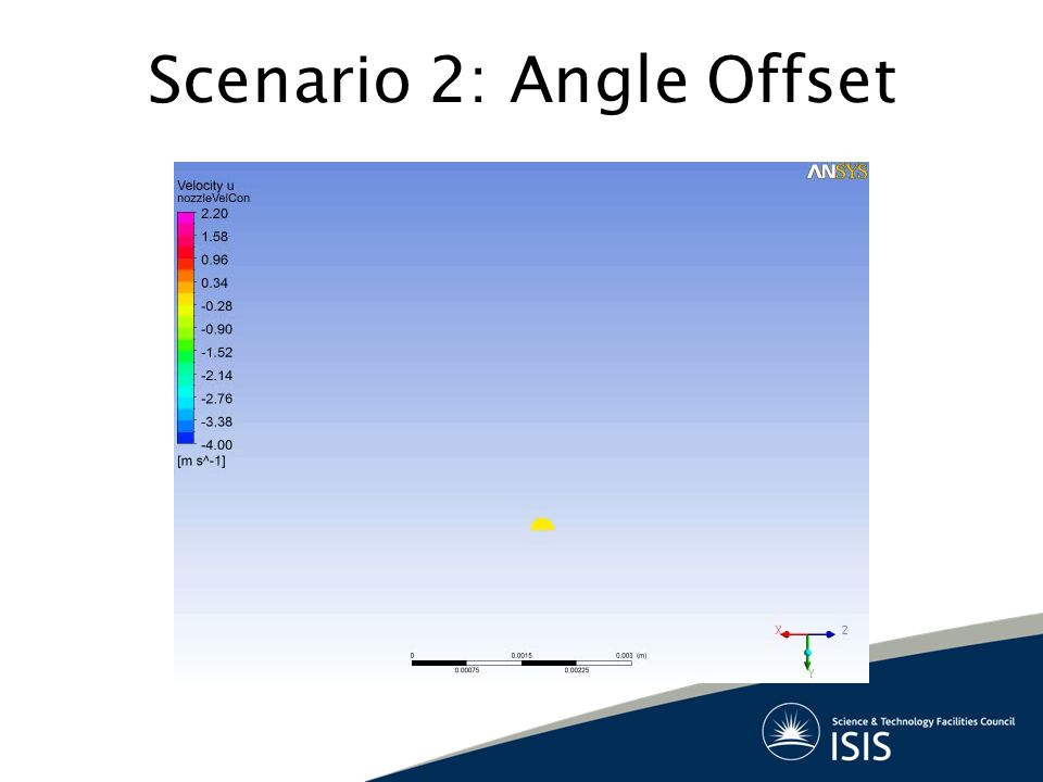
Tube offset in position relative to hole in vane Resting flush against one side of hole Tube offset in angle relative to hole in vane Resting against both sides of hole Worst Case Misalignments

55
Scenario 1: Position Offset

58
Scenario 2: Angle Offset

62
Main Cooling Channel Along the Vane Length

63
Other RFQs use many channels! Indian SNS: Six per quadrant American SNS: Four per quadrant Chinese SNS: Five per quadrant HINS (FNAL): Three per quadrant
: Three per quadrant.")
64
Replace Distributed Channels With One Large Water Bath

65
Bath milled into vane from air side Plate bolted on to cover the bath and allow water in/out Baffle shaped to leave 2-3mm gap around edges of bath so the water flow is properly directed

66
One channel per quadrant Three channels per quadrant One bath per quadrant One directed-flow bath per quadrant

67
One channel per quadrant Three channels per quadrant One bath per quadrant One directed-flow bath per quadrant 32°C 29°C 34°C 31°C

68
Three channels per quadrant One directed-flow bath per quadrant A water bath with directed flow achieves very similar copper temperatures to a “normal” multiple-cooling-channel layout Novel Simple Effective BUT: There is always a variation of temperature (and hence copper expansion) along the vane length. How does this affect local E-fields? How does it affect beam dynamics? Do vane modulations complicate temperature distribution? What amount of growth is acceptable?

69
Summary Squirt nozzle idea borrowed from ISIS & SNS –Tried and tested design Whole system is outside vacuum –Easy to machine, maintain or modify Simulated flow rates, HTCs etc match predictions RFQ is well cooled at full RF power –But is it good enough from beam dynamics POV? Nozzle misalignments don’t affect performance Flow through different main channels tested –Directed bath performs as well as many channels

70
Questions?

71
Extra Slides

72
Flow Velocity (m/s)
")
73
Water Temperature (K)
")
74
Heat Transfer Coefficient for Different Sized Pipes 127 l/min! 11.8 l/min 0.012 l/min 0.07 l/min 1.5 l/min HTC / Wm -2 K -1 Turbulent Flow

75
CFD Mesh Used

76
Eigenmode Solver Surface H-Field Results

77
Structural Deformation Longitudinal Displacement / mm Vertical Displacement / mm Vanes move toward each other by ~30 µm. Walls move outward by ~150 µm. Vane ends move toward end wall by ~300 µm.

78
Frequency Shift vs. Input Power

Similar presentations


 Types of Pumps and Pump Sizing This Week:>")


