Download presentation
Presentation is loading. Please wait.

1
1. Aerosol Instrumentation – In Situ Measurement of Particle Size and Number Example of size distribution (Number size distribution with three log- normal modes measured in the Arctic (y-axis linear): How do we measure particle number and particle size ?
: How do we measure particle number and particle size .")
2
1. Aerosol Instrumentation – Measurement of particle size and number A. Particle Size - Condensation Particle Counter Important instruments in aerosol technology are Condensation Particle Counters (CPC). They are used to measure the particle number concentration down to the nanometer size range. The particles are enlarged due to supersaturation and a subsequent condensation of a condensable gas (normally Butanol, now also water!). The particles reach a size at which they can be optically detected. The number concentration is measured for all particle larger than the lower detection diameter.
. They are used to measure the particle number concentration down to the nanometer size range. The particles are enlarged due to supersaturation and a subsequent condensation of a condensable gas (normally Butanol, now also water!). The particles reach a size at which they can be optically detected. The number concentration is measured for all particle larger than the lower detection diameter..")
3
CPCs are used to measure the number concentration in the submicrometer size range. The lower detection diameter is determined by: 1. the Kelvin diameter (supersaturation) 2. diffusion coefficient of the condensable gas 3. the particle material The upper and lower detection limits are specific for each CPC type. Following techniques have been used to count particles in the past: 1. microscope (particles collected on a plate) 2. picture (cloud chamber) 3. extinction 4. single particle in a continuous flow There are two types of CPCs: 1. expansion chamber CPC (extinction) – not used in science anymore 2. continuous flow CPC (single particle) – most popular in situ aerosol instrument
 2. diffusion coefficient of the condensable gas 3. the particle material The upper and lower detection limits are specific for each CPC type. Following techniques have been used to count particles in the past: 1. microscope (particles collected on a plate) 2. picture (cloud chamber) 3. extinction 4. single particle in a continuous flow There are two types of CPCs: 1. expansion chamber CPC (extinction) – not used in science anymore 2. continuous flow CPC (single particle) – most popular in situ aerosol instrument.")
4
A.1 Continuous Flow CPC Modern CPCs operate with continuous aerosol flows and are able to count each single particle. Model TSI 3010, 3760, 3762: Principal: continuous flow, single particle counting Lower detection diameter: 10 nm (Model 3025: 3 nm) Concentration range: 0-10,000 cm -3 (Model 3025: 0-10 5 cm -3 )
 Concentration range: 0-10,000 cm -3 (Model 3025: cm -3 ).")
5
Schematic sketch of the CPC models TSI 3010 (also 3760, 3762) Counting efficiency curveResponse time
 Counting efficiency curveResponse time")
6
Functioning: The aerosol flow is saturated with butanol in a slightly heated saturator. The the temperature of the butanol-aerosol mixture is decreased by 17-27°C in the condenser of the CPC. Here, the butanol become supersaturated and condenses onto the particles. The particles grow to droplets of several µm in diameter. The droplet flow is focused in a nozzle and introduced into a counting optic. The droplets pass a laser beam, and each single particle creates a light pulse. Pulses with an amplitude above a certain threshold are counted. The particle number concentration can be calculated by knowing the aerosol flow rate.

7
A.2 Aerodynamic Particle Sizer (APS) The APS measures the aerodynamic particle diameter and can thus determine the aerodynamic particle size distribution. Aerodynamic diameter: The aerodynamic particle diameter is defined as: „Diameter of a spherical particle with the density of One and the same sedimentation velocity of the measured particle". = dynamic shape factor 0 = 1g/cm 3, e.g. water

8
Specification of the APS: The APS determines the aerodynamic number size distribution with a high time resolution. The aerodynamic particle size range of the APS model TSI 3321 is between 0.5 and 20 µm. Solid and non-volatile particles can be measured.

9
Schematic of the APS: The main part of the APS are the acceleration nozzle and the laser anemometer.

10
Acceleration nozzle: The acceleration nozzle consists of an inner and out nozzle. The inner nozzle focuses the aerosol flow. The aerosol flow is then surrounded by the sheath air flow. The entire flow is then accelerated through the outer nozzle. The total flow rate of 5 l/min consists of 1 l/min aerosol flow and 4 l/min particle-free sheath air. The velocity of the aerosol flow in the center is assumed to be constant. Due to inertia, particles with a large aerodynamic diameter cannot follow the acceleration. This means that particle with different aerodynamic diameters have different velocities directly behind the nozzle (calibrated instrument !).
..")
11
Laser anemometer: The laser anemometer measures the time-of-flight between two laser beams. The laser beams are positioned directly behind the outer nozzle. Particles passing the laser beams emit two light pulses. The time difference between the two pulse maxima is the time-of-flight. The time-of-flight is a measure for the aerodynamic particle diameter. The relation between time-of-flight and aerodynamic particle size must be calibrated for each device.

12
Optical measurements: Beside the determination of the aerodynamic particle size, the signal can also be taken to determine the optical diameter (see also Optical Particle Counter OPC). Each particle is classified in relation to the refractive index of latex spheres.

13
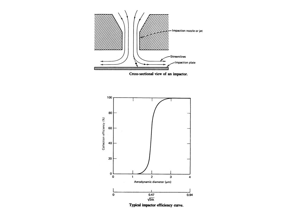
A.3 Impactors A.3.1 Operation Principle Impactors utilize the mechanism of inertial impaction to deposit particles onto impaction surfaces. Technically, impactors are realized as nozzle – impaction - plate configuration. Flowing through the nozzle the aerosol flow is accelerated. The impaction plate causes a strong bending of the gas stream lines. Small particles, because of their small inertia, can follow the gas stream lines and are not deposited. Large particles, due to their higher inertia, cannot follow the stream lines are deposited on the impaction plate. An impactor separates the aerosol particles into two size (mass) fractions.
 fractions..")
14
A.3.2 Mathematical Description The important parameter for the description of impactors is the Stokes-Number: P = particle relaxation time u = gas velocity D j = nozzle diameter The Stokes-number is defined as the ratio of particle stopping distance to the nozzle radius. In first approximation, the "Cut-Off„ diameter d 50 of an impactor can be determined (500 1.5) by: Impactor type rectangular nozzle round nozzle 0,22 0,53 0,47 0,73
 by: Impactor type rectangular nozzle round nozzle 0,22 0,53 0,47 0,73.")
16
The idealized transfer function of an impactor, i.e. the deposition efficiency as function of particle size, can be described by means of a step-function at particle size d 50. Real impactors exhibit a deposition characteristic, i.e. their transfer function deviates from the idealized transfer function. Impactor transfer functions are often plotted as function of.

17
A.3.3 Determination of Particle Size Distributions For the determination of particle size distributions multiple impactors are operated in series. A device like this is called a cascade or multi-stage impactor. In a cascade impactor, the cut-off-diameter is decreased from stage to stage. For complete deposition of the small particles, down-stream of the last impactor stage, a backup filter is utilized. Each stage is equipped with an exchangeable impaction plate. The particle mass / number deposited in each stage is determined gravimetrically, chemically or optically. From these particle masses / numbers, the particle size distribution can be reconstructed if the transfer functions of the different stages are known.

18
To decrease the cut-off diameter from stage to stage is achieved by a) decreasing the nozzle diameters (increase in particle/air velocity) b) and/or decreasing the number of nozzles c) and/or decreasing the pressure (increase in slip correction).
 decreasing the nozzle diameters (increase in particle/air velocity) b) and/or decreasing the number of nozzles c) and/or decreasing the pressure (increase in slip correction).")
19
B. Particle Size - Differential Mobility Analyzer B.1 Electric Mobility Electrically charged particles move in an electric field according to their electrical mobility. The electrical mobility Z P of a particle with a certain electric charge is defined to (given in [cm 2 /Vs]): With v e derived analog to the sedimentation velocity The electrical mobility depends mainly on the particle size and electrical charge. The smaller the particle the higher is the electrical mobility. The higher the electrical charge the higher is the electrical mobility. n = number of charges e = elementary charge B = particle mobility (“velocity per unit force”)
: With v e derived analog to the sedimentation velocity The electrical mobility depends mainly on the particle size and electrical charge. The smaller the particle the higher is the electrical mobility. The higher the electrical charge the higher is the electrical mobility. n = number of charges e = elementary charge B = particle mobility ( velocity per unit force ).")
20
B.2. Functioning Assumption: All particles carry only one electrical charge. The electrical mobility is than only a function of the particle size in case of constant temperature and pressure. Example: An electrically charged polydisperse aerosol is led through a plate capacitor. Electrically charged particles are separated and deposited according their size.

21
Plate mobility analyzer: aerosol sheath air

22
Theory of a plate mobility analyzer: The most simple mobility analyzer is a plate capacitor. A laminar particle-free sheath air flow Q sh is led through the capacitor (x- direction). An electric field is put between the plates (z-direction). The aerosol flow Q A (x-direction) is fed into the capacitor close to one plate. The particle velocity in z-direction is defined to: The particle velocity in x-direction is given to:
. An electric field is put between the plates (z-direction). The aerosol flow Q A (x-direction) is fed into the capacitor close to one plate. The particle velocity in z-direction is defined to: The particle velocity in x-direction is given to:.")
23
with The electrical mobility for a certain deposition place is given to: w = width of the capacitor d = distance between plates The voltage to select a certain mobility can be calculated by:

24
Differential Mobility Analyzer (DMA): The voltage to select a certain electrical mobility incl. the electrical mobility from Stokes‘ law can be calculated to: e = elemental charge 1,602·10 -19 As n = number of charges The particle size for a certain deposition place is: ∆D P = 1 nm or D P =10nm ± 0.5nm

25
Recap How do we measure particle number and particle size ? Multistage impactor Aerosol Particle Sizer Optical Particle Counter Combination of DMA+CPC (most common application for atmospheric measurements)
 .")
26
B.2 Electrical Mobility Spectrometer The DMA can be used to measure the number size distribution of a polydisperse aerosol. There exist two different principles: The voltage is increased stepwise (DMPS) The voltage is continuously increased (SMPS) A electrical mobility spectrometer consists of: a pre-impactor a bipolar diffusion charger a DMA a CPC
 The voltage is continuously increased (SMPS) A electrical mobility spectrometer consists of: a pre-impactor a bipolar diffusion charger a DMA a CPC.")
27
A electrical mobility spectrometer can measure a size distribution only for a certain size range. This size range depends on the DMA-geometry and the sheath air flow rate. Longer DMA larger particle diameter Higher sheath air flow rate smaller particle diameter

28
B.2.1 Differential Mobility Particle Sizer (DMPS) A pre-impactor removes all particles larger than the upper diameter of the size range to be measured The particles are brought in the the bipolar charge equilibrium in the bipolar diffusion charger. A computer program sets stepwise the voltage for each selected mobility bin. After a certain waiting time, the CPC measures the number concentration for each mobility bin. The result is a mobility distribution. The number size distribution must be calculated from the mobility distribution by a computer inversion routine.

29
B.3 Applications of DMPS-Systems B.3.1 Twin Differential Mobility Particle Sizer (TDMPS) A combination of two electrical mobility spectrometers allows to measure the size distribution of the entire submicrometer size range.
 A combination of two electrical mobility spectrometers allows to measure the size distribution of the entire submicrometer size range.")
30
B.3.2 Tandem Differential Mobility Analyzer (TDMA) A TDMA is a system where two DMAs are applied in series. A TDMA can measure the mixing state of a defined particle size in terms of a certain aerosol parameter. The first DMA selects a monodisperse aerosol out of the entire aerosol population. The monodisperse aerosol is modified in a conditioner The new size spectrum is determined with the second DMA Applications: Bipolar charge distribution Hygroscopicity Volatility

31
Hygroscopicity-Tandem-Differential-Mobility-Analyzer (HTDMA)
")
32
Examples of HTDMA measurement

33
Volatility-Tandem-Differential-Mobility-Analyzer (VTDMA)
")
34
Examples of VTDMA measurements: Volatility spectra of 30, 50, 80, and 150 nm particles measured near a freeway for 280°C in comparison to 25°C.

Similar presentations