Download presentation
Presentation is loading. Please wait.

1
50.003: Elements of Software Construction
Week 2 Introduction to Software Design

2
Plan for the Week Class 1: What is Software Design?
Class 2:Software Design Documentation UML: Use Case Diagrams UML: Sequence Diagrams Class 3: UML: Class Diagrams UML: State Machine Diagrams

3
System Implementation
Software Design User Requirements How do we design it such that we can implement a system which fulfills the requirements? System Implementation

4
What is software design?

5
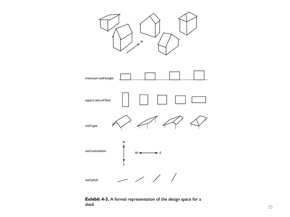
What is Design? choice 1 Design Space choice 2 choice 3 choice 4
Good Designs ch. A ch. B ch. C ch. D ch. E ch. F ch. G

6
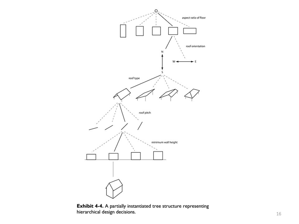
The Rational Model Input: Goal, Desiderata, Utility function, Constraints, Design tree of decisions Until (“good enough”) or (time runs out) { Do another design (to improve utility function) Until design is complete Backtrack up design tree Explore a path not searched before While design remains feasible, make another design decision EndWhile EndUntil EndDo Take best design
 or (time runs out) { Do another design (to improve utility function) Until design is complete Backtrack up design tree Explore a path not searched before While design remains feasible, make another design decision EndWhile EndUntil EndDo Take best design")
7
Software Design is Hard
For software systems, we don’t exactly know the user requirements. “A chief service of a designer is helping clients discover what they want designed.”

9
Software Design is Hard (cont’d)
Even if the user requirements are clear, we wouldn’t know all the design choices. Experienced designers do better design because They know better about the design choices. They know better about the relations between the choices.

10
Criticizing the Rational Model

11
Is this similar to certain software development process?

12
Software Design is Hard (cont’d)
Even if we know all the design choices, the combinations of design choices are exponential and therefore it may not be easy to find a good design.

13
COMBINATORIAL COMPLEXITY

20
ADDRESSING COMPLEXITY IN DESIGN
Miller’s Law

21
Strategies for addressing complexity
Decomposition Abstraction Hierarchy

22
Decomposition Divide et impera (divide and rule) is a technique of mastering complexity in vogue since ancient times [Dijkstra 1979]. Key idea: Break down a system into smaller and more manageable parts, so that the channel capacity of our comprehension is not breached.
![Decomposition Divide et impera (divide and rule) is a technique of mastering complexity in vogue since ancient times [Dijkstra 1979].](http://slideplayer.com/slide/4175504/13/images/22/Decomposition+Divide+et+impera+%28divide+and+rule%29+is+a+technique+of+mastering+complexity+in+vogue+since+ancient+times+%5BDijkstra+1979%5D..jpg "Key idea: Break down a system into smaller and more manageable parts, so that the channel capacity of our comprehension is not breached.")
23
Abstraction One of the most frequently used words in the context of software design Key idea: Unable to master the entirety of a complex object, we choose to ignore its inessential details, dealing instead with the generalized, idealized model of the object [Booch et al. 2007].

24
Hierarchy Whenever we examine something new or something that seems to be complex, we try to see what common characteristic it shares with other things we know, or if it is part of something we have seen earlier. Key idea: “Is a” relation: E.g. a car is a locomotion device with wheels “Part of” relation: A part of a car is the engine

25
Cohort Exercise 1 (25 min) Design and implement a program that supports accepting two complex numbers from the user; adding, subtracting, multiplying, and/dividing them; and reporting each result to the user.

26
Cohort Exercise 1 (cont’d 10 min)
Support complex numbers in both rectangular form and polar form.

27
Further Reading Parnas, David L., (December 1972). “On the Criteria to be Used in Decomposing Systems into Modules". Communications of the ACM. Volume 15, Number 12, pages
. On the Criteria to be Used in Decomposing Systems into Modules . Communications of the ACM. Volume 15, Number 12, pages")
28
The Languages of software development

29
The Spectrum of Languages
Languages for implementation: programming languages: precise and executable but perhaps not a good media for communication Languages for software development process: modelling languages: often visual, often not executable, high-level, aiming for communication between different parties in software development processes Languages for user requirements: Structured English: not visual, not executable, not precise, extremely flexible

30
Lineage of programming languages
Check this out:

31
Generations of PL

32
The High and Low of PL

33
Why Modeling Languages?
Modeling languages are mainly for documentation and communication. Documentation is an important part of software engineering. Documentation is perhaps a part of any software development process. It forms the basis of an iterative design process. It forms the basis of effective communication among three parties, through time. There are formal modeling languages and informal ones.

34
Unified Modelling Language
UML is a visual language that lets you model processes, software, and systems. UML is made up of notation and diagrams Notation consists of the elements that work together in a diagram, such as symbols, connectors, notes, values, etc. Diagrams are pictorial representation of a process, the system, or some part of. UML is defined as a set of specifications created and distributed by the Object Management Group (OMG).
.")
35
Unified Modelling Language
UML is extensible. There are 14 UML diagram types. UML is flexible.

36
Why so many diagrams?

37
We Will Cover Use Case Diagrams Sequence Diagrams Class Diagrams
State Diagrams

38
User Requirements: a Case Study
Preeti is leading a team of software engineers engaged in building the system. Kuber Bank (KB) has been in the banking business for over thirty years with branches all over India. About 15 years ago, the branches were computerized and they are currently connected through a nation-wide network. To keep up with the competition, KB needs to offer online banking facilities to its customers. Preeti’s organization has won the contract to ‘Webify’ KB. An initial meeting was arranged between KB’s senior management and Preeti’s team to understand the scope of the projects. - ‘So, as a first step, it would be good for us to know the broad requirements you have in mind’, began Preeti. - ‘Well, we want to let the customers do online all they can do at a branch’, Sanjeev Kumar, KB’s senior vice-president, replied.
 has been in the banking business for over thirty years with branches all over India. About 15 years ago, the branches were computerized and they are currently connected through a nation-wide network. To keep up with the competition, KB needs to offer online banking facilities to its customers. Preeti’s organization has won the contract to ‘Webify’ KB. An initial meeting was arranged between KB’s senior management and Preeti’s team to understand the scope of the projects. - ‘So, as a first step, it would be good for us to know the broad requirements you have in mind’, began Preeti. - ‘Well, we want to let the customers do online all they can do at a branch’, Sanjeev Kumar, KB’s senior vice-president, replied.")
39
Roles and Functionality
Administrator can: View transactions across all accounts Add transactions to any account Delete transactions from any account Review all messages sent by users Reply to messages sent by users User can: View their profile information View list of their accounts with the bank View transactions for each of their accounts Send messages to the bank View history of messages they have sent to the bank and replies from the bank

40
Contracting: Glossary
Account: the bank account held by a user with Kuber Bank (KB), identified by a unique account number Administrator: A special type of user who has unique privileges in manipulating information relevant to KBO. KBO: the Kuber Bank Online system User: An account holder of KB who is allowed by KB to use KBO … Can the Administrator be an User too?
, identified by a unique account number. Administrator: A special type of user who has unique privileges in manipulating information relevant to KBO. KBO: the Kuber Bank Online system. User: An account holder of KB who is allowed by KB to use KBO. … Can the Administrator be an User too")
41
Contracting: Requirement Description
KBO_Req_01: Recording Transaction Details in KBO by administrator Administrator shall access transaction information of a particular account on a periodic basis and record the same in the KBO system such that user can view them through the Web interface. The transaction information will be available to be accessed by the administrator in the existing Master Ledger (ML) system. Details for a transaction need to be available at KBO for viewing by a user within 48 hours after the transaction have been initiated by the user. Is this good enough?
 system. Details for a transaction need to be available at KBO for viewing by a user within 48 hours after the transaction have been initiated by the user. Is this good enough")
42
Description of Requirements
KBO_Req_01 Expanded Administrator shall manually access transaction information for a particular account on a periodic basis from the existing Master Ledger system. (Automation of this access mechanism is outside the scope of KBO’s current release and may become a Requirement for a future release.) Administrator shall record the transaction information for a particular account accessed from the ML system, in the KBO system. Only successful transactions need to be available at KBO for viewing by users within 48 users after they have been initiated by the user. Users will be notified of failed transactions through procedures outside the scope of KBO’s current release.
 Administrator shall record the transaction information for a particular account accessed from the ML system, in the KBO system. Only successful transactions need to be available at KBO for viewing by users within 48 users after they have been initiated by the user. Users will be notified of failed transactions through procedures outside the scope of KBO’s current release.")
43
Description of Requirements
KBO_Req_01: Non-functional Parts Ensuring transactions are recorded in a format that makes it reasonably easy to be understood by users. Ensuring transactions are correctly recorded for the appropriate user accounts. Ensuring successful transactions are recorded at KBO within 48 hours of their initiation. Ensuring large volumes of transaction for a particular account within a particular period of time can be handled.

44
Use Case “To my knowledge, no other software engineering language construct as significant as use cases has been adopted so quickly and so widely among practitioners. I believe this is because use cases play a role in so many different aspects of software engineering.” Ivar Jacobson Founding father of UML Creator of Use Case Diagram

46
Use Case General comments and notes describing the use case.
Requirements - The formal functional requirements of things that a Use Case must provide to the end user, such as <ability to update order>. These correspond to the functional specifications found in structured methodologies, and form a contract that the Use Case performs some action or provides some value to the system.

47
Use Case Constraints - The formal rules and limitations a Use Case operates under, defining what can and cannot be done. These include: Pre-conditions that must have already occurred or be in place before the use case is run; for example, <create order> must precede <modify order> Post-conditions that must be true once the Use Case is complete; for example, <order is modified and consistent> Invariants that must always be true throughout the time the Use Case operates; for example, an order must always have a customer number.

48
Use Case Scenarios – Formal, sequential descriptions of the steps taken to carry out the use case, or the flow of events that occur during a Use Case instance. These can include multiple scenarios, to cater for exceptional circumstances and alternative processing paths. These are usually created in text and correspond to a textual representation of the Sequence Diagram. There are recommended formats (refer to Chapter 11, Fully Dressed Use Case Template of “WRITING EFFECTIVE USE CASES”) Scenario diagrams - Sequence diagrams to depict the workflow; similar to Scenarios but graphically portrayed. Additional attributes, such as implementation phase, version number, complexity rating, stereotype and status.
 Scenario diagrams - Sequence diagrams to depict the workflow; similar to Scenarios but graphically portrayed. Additional attributes, such as implementation phase, version number, complexity rating, stereotype and status.")
49
Flow of Events Basic flow of events
Is the most common pathway. It usually depicts a perfect situation, in which nothing goes wrong. Alternative flow of events Is a pathway that is still considered a good pathway; it’s just not the most heavily travelled one. Exception Flow of Events Things don’t always go as planned. An exception is an error condition that is important enough to the application to capture.

50
Cohort Exercise 2 (15 min) Work as a group, document one use case of the App that you are developing.
 Work as a group, document one use case of the App that you are developing.")
51
UML 2

52
UML Diagrams In UML 2 there are two basic categories of diagrams: structure diagrams and behavior diagrams. The purpose of structure diagrams is to show the static structure of the system being modeled. They include the class, component, and or object diagrams. Behavioral diagrams, on the other hand, show the dynamic behavior between the objects in the system, including things like their methods, collaborations, and activities.

53
Use Case Diagrams Definition: a diagram that shows a set of use cases and actors and their relationships. Use case diagrams represent system functionality, the requirements of the system from the user’s respective.

54
Actors Actors are the people or systems that provide or receive information from the system; they are among the stakeholders of a system, which could be human beings, other systems, timers and clocks or hardware devices. Actors that stimulate the system and are the initiators of events are called primary actors (active). Actors that are only receive stimuli from the system are called secondary actors (passive).
. Actors that are only receive stimuli from the system are called secondary actors (passive).")
55
Who are the Actors? Actors Who/what will be interested in the system?
Who/what will want to change the data in the system? Who/what will want to interface with the system? Who/what will want information from the system?

56
Use Case in Use Case Diagrams
Is a description of a set of sequences of actions, including variants, that system performs that yields an observable value to an actor. Should ideally begin with a verb. Open Account

57
Use Case Diagram: Example
Apply Course Avoid showing communications or behaviors in use case diagram.

58
Notations: between Use Cases
include Specifies that the source use case explicitly incorporates the behaviors of another use case at a location specified by the source extend Specifies that the target use case extends the behaviors of the source <<include>> <<extend>>

59
Use Case Diagram: Example
Login <<include>> Apply Course <<extend>> Read Course Description

60
Include and Extend The use of include and extend is discouraged simply because they add unnecessary complexity to a Use Case diagram Since the primary purpose of use cases is to show user centered functionality, the precedence of use cases takes little importance.

61
Granularity of Use Cases
Add References Manage References Delete References Re-order References Generally, a use case should embody sufficient levels of granularity without which the use case may not be rendered as useful.

62
Cohort Exercise 3 (5 min) Draw individually the user case diagram for KBO.
 Draw individually the user case diagram for KBO.")
63
Sequence Diagram A sequence diagram is an interaction diagram that highlights the order in which the messages are exchanged. Sequence diagram complements a user case with details on the workflow of events.

64
Lifelines lifeline notation elements are placed across the top of the diagram. Lifelines represent either roles or object instances that participate in the sequence being modeled. An object named freshman of type Student.

65
Messages To show an object (i.e., lifeline) sending a message to another object, you draw an arrow to the receiving object. These return messages are optional and so dotted.

66
Arrows and Orders a solid arrowhead if a synchronous call operation
a stick arrowhead if an asynchronous signal the order of the messages is defined two rules: On the same lifeline, a higher message precedes a lower message Message sending precedes message receiving

67
Message to Itself An object can send a message to itself.

68
Guards

69
Alternatives

70
Option

71
Loops

72
Parallel

73
Referencing

74
Cohort Exercise 4 Draw as a group a sequence diagram for one of your use cases.

75
Class diagrams A class diagram depicts a set of classes, interfaces, and collaborations and their relationships. Class diagrams are used most frequently while modelling object-oriented systems.

76
Basics Class name Class attribute list Class operations list

77
Inheritance

78
Associations When you model a system, certain classes will be related to each other. Bi-directional (standard) association: both classes are aware of each other and their relationship
 association: both classes are aware of each other and their relationship.")
79
Multiplicity Indicator Meaning 0..1 Zero or one 1 One only 0..*
Zero or more * 1..* One or more 3 Three only 0..5 Zero to Five 5..15 Five to Fifteen

80
Uni-Directional Association
In a uni-directional association, two classes are related, but only one class knows that the relationship exists.

81
Association: Packages

82
Interfaces Dotted line indicates it’s NOT inheritance.

83
Cohort Exercise 5 (15 min) Draw a class diagram for the following scenario. In a university there are different classrooms, offices and departments. A department has a name and it contains many offices. A person working at the university has a unique ID and can be a professor or an employee. A professor can be a full, associate or assistant professor and he/she is enrolled in one department. Offices and classrooms have a number ID, and a classroom has a number of seats. Every employee works in an office.

84
State Machine Diagrams: History
Finite state automata have a long history of being used as a modelling language. Example: the following describes a light Rich theoretical development based on finite state automata: Turing machine, Pushdown automata, Büchi Automata, etc. Can we model everything using finite-state automata?

85
State Machine Diagrams
A UML state machine diagram is a behavior diagram which shows discrete behavior of a part of designed system through finite state transitions. Describing the behavior of a class instance. State machine diagrams can also be used to express the usage protocol of part of a system. Protocol state machines are used to express usage protocols and can be used to specify the legal usage scenarios of classifiers, interfaces, and ports.

86
State Machine Essence States Initial and final states Transitions

87
State Machine Example

88
State Machine Diagrams: More
State actions Self-looping actions

89
Compound states

90
State Machine Referencing

91
Junction Pseudo State

92
History States

93
Concurrent Regions

94
Cohort Exercise 6 (10 min) A hardware update wizard can be in three states as follows: 1. Displaying a hardware update window. 2. Searching for new hardware. 3. Displaying new hardware found. The wizard starts by displaying a hardware update window. While displaying this window, the user can press a "Search" button to cause the wizard to start searching for new hardware, or the user can press a "Finish" button to leave the wizard. While the wizard is searching for new hardware, the user may cancel the search at any time. If the user cancels the search, the wizard displays the hardware update window again. When the wizard has completed searching for new hardware, it displays the new hardware found. Draw a state machine diagram that represents the function of the hardware update wizard just described.

95
Other UML diagrams A set of object and their relationships are shown in an object diagram, which is a snapshot of instances of classes represented in class diagrams. A component diagram represents an encapsulated class and its interfaces, ports, and internal structure which may consist of nested structures and connectors.

96
Other UML diagrams An interaction diagram shows the interaction between objects or roles, via sending of messages back and forth between them. An activity diagram is UML’s closest counterpart to the flow chart of the structural programming world; it shows the structure of a process or other computation with a step-by-step flow of control and data. A deployment diagram represents the configuration of run-time processing nodes and components that run on them

97
UML diagrams A package diagram depicts the decomposition of the model into organizational units and how they are dependent amongst one another. An interaction overview diagram represents a hybrid of an activity diagram and a sequence diagram.

Similar presentations


 Presentation By - SANDEEP REDDY CHEEDEPUDI (Student No: 17037032) - VISHNU CHANDRADAS (Student.>")


 – Part One Ku-Yaw Chang Assistant Professor.>")


 SYSC 3100 - System Analysis and Design.>")
