Download presentation
Presentation is loading. Please wait.

1
EE202 Supplementary Materials for Self Study Circuit Analysis Using Complex Impedance Passive Filters and Frequency Response

2
Acknowledgment Dr. Furlani and Dr. Liu for lecture slides Ms. Colleen Bailey for homework and solution of complex impedance Textbook: Nilsson & Riedel, “Electric Circuits,” 8 th edition

3
Steady-State Circuit Response to Sinusoidal Excitation - Analysis Using Complex Impedance

4
Why Sinusoidal? US Power Grid 60Hz Sinusoidal

5
Household Power Line

6
Household Circuit Breaker Panel 240V Central Air 120V Lighting, Plugs, etc.

7
Single Frequency Sinusoidal Signal

8
Amplitude – Peak-to-peak – Root-mean-square Frequency – Angular Frequency – Period

9
Trigonometry Functions Appendix F

10
Other Periodic Waveforms Fundamental and Harmonics

11
Resistor Only Circuit I=V/R, i (t)= v (t)/R Instantaneous Response
= v (t)/R Instantaneous Response")
12
R-L Circuit TransientSteady-state

13
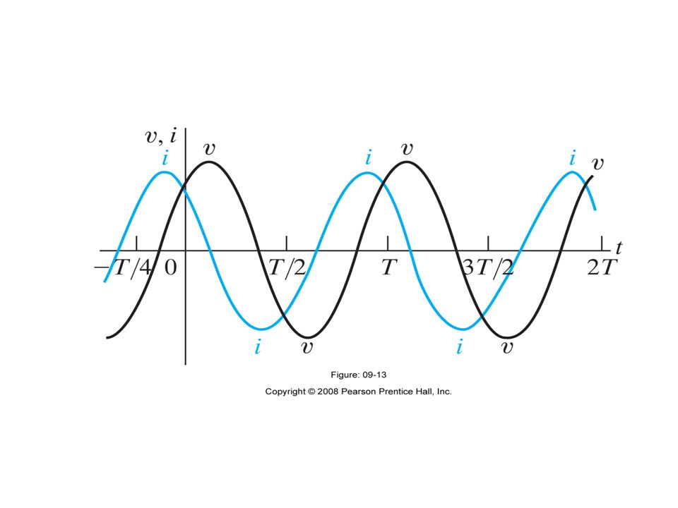
Phase Shift Time Delay or Phase Angle: t / T *2 or *360-degree

14
Phasor – Complex Number Y Imag(Z) X Real(Z) Z Real(Z)+j Imag(Z) tan -1 (Y/X) Reference
 X Real(Z) Z Real(Z)+j Imag(Z) tan -1 (Y/X) Reference")
15
Complex Number

16
Phasor Solution of R-L Circuit

17
Observations Single Frequency for All Variables Phasor Solution of Diff Eq. – Algebraic equation – Extremely simple Phase – Delay between variables Physical Measurements – Real part of complex variables v = Real{V}; i = Real{I}

18
Resistor

19
Instantaneous Response

20
Inductor

22
Capacitor

24
Impedance in Series Complex Impedance Resistance, Reactance

25
=5000 rad/sec Example

26
Apply Z L =j L, Z C =1/j C Z ab =90+j(160-40)=90+j120=sqrt(90 2 +120 2 )exp{jtan -1 (120/90)} =150 53.13 degree I=750 30 deg / 150 53.13 deg = 5 -23.13 deg=5exp (-j23.13 o )
=90+j120=sqrt( )exp{jtan -1 (120/90)} =150 degree I=750 30 deg / 150 deg = 5 deg=5exp (-j23.13 o )")
27
Impedance in Parallel Complex Admittance Conductance, Susceptance

28
=200000 rad/sec Example

29
Apply Z L =j L, Z C =1/j C Series: Use Z; Parallel: Use Y Y=0.2 36.87 deg; Z=5 -36.87 deg V=IZ=40 -36.87 deg

30
Kirchhoff’s Laws Same Current at a Node – Addition of current vectors (phasors) Voltage Around a Loop or Mesh – Summation of voltage vectors (phasors)
 Voltage Around a Loop or Mesh – Summation of voltage vectors (phasors)")
31
Delta-T Transformation

32
Example

33
Delta-T Transformation

34
Series, Parallel, Series

35
Another Delta-T Transformation

36
Thevenin and Norton Transformation

37
Thevenin Equivalent Circuit

38
Norton Equivalent Circuits

41
Voltage divider Vo=36.12-j18.84 (V)
")
43
Find V Th V x =100-I*10, V x =I*(120-j40)-10*V x ; solve V x and I V TH =10V x +I*120=784-j288 (V)
-10*V x ; solve V x and I V TH =10V x +I*120=784-j288 (V)")
44
Find Z Th Calculate I a Determine V x Calculate I b Z Th =V T /I T =91.2-j38.4 (Ohm)
")
45
Transformer Time differentiation replaced by j

46
AC Sine Wave, Ideal Transformer Voltage and Current Power Conserved

47
Transformer Power Applications – Convert voltage v out =(N 2 /N 1 ) v in Signal Applications – Impedance transformation X ab =(N 1 /N 2 ) 2 X L – Match source impedance with load to maximize power delivered to load
 v in Signal Applications – Impedance transformation X ab =(N 1 /N 2 ) 2 X L – Match source impedance with load to maximize power delivered to load")
48
Power Calculations

49
Frequency Response of Circuits Analysis Over a Range of Frequencies Amplifier Uniformity Filter Characteristics – Low pass filter – High pass filter – Bandpass filter – Equalizer

50
RC Filters High Pass Low Pass

51
Frequency Response High Pass Low Pass

52
Bode Plot Log 10 (f) – Compress many orders of magnitude Vertical scale – Linear – log: 10 log 10 (Vo/Vin)
 – Compress many orders of magnitude Vertical scale – Linear – log: 10 log 10 (Vo/Vin)")
53
Bode Plot Appendix D, Appendix E

54
Summary Sinusoidal, Steady-State Analysis Complex Impedance Z=j L Z=1/j C All Circuit Analysis Methods Apply Analysis Power Systems Frequency Response of Circuits

55
Homework Problem7.pdf Solution7.pdf

56
Frequency Response & Passive Filters 1. Filters 2. Low Pass Filter 3.High Bass Filter 4.Band Pass Filter 5.Band Stop Filter 6.Series RLC Resonance 4Parallel RLC Resonance

57
90.7 WSDL Ocean City 90.3 WHID Salisbury Frequency (MHz) 90.5 WKHS Worton 91.3 WMLU Farmville 90.9 WETA Washington 91.1 WHFC Bel Air 91.5 WBJC Baltimore Tuning a Radio Consider tuning in an FM radio station. What allows your radio to isolate one station from all of the adjacent stations?

58
Filters A filter is a frequency-selective circuit. Filters are designed to pass some frequencies and reject others. Frequency (MHz) 90.9 WETA Washington
 90.9 WETA Washington.")
59
Different Kinds of Filters There are four basic kinds of filters: –Low-pass filter - Passes frequencies below a critical frequency, called the cutoff frequency, and attenuates those above. –High-pass filter - Passes frequencies above the critical frequency but rejects those below. –Bandpass filter - Passes only frequencies in a narrow range between upper and lower cutoff frequencies. –Band-reject filter - Rejects or stops frequencies in a narrow range but passes others.

60
Active and Passive Filters Filter circuits depend on the fact that the impedance of capacitors and inductors is a function of frequency There are numerous ways to construct filters, but there are two broad categories of filters: – Passive filters are composed of only passive components (resistors, capacitors, inductors) and do not provide amplification. – Active filters typically employ RC networks and amplifiers (opamps) with feedback and offer a number of advantages.
 with feedback and offer a number of advantages..")
61
Impedance vs. Frequency Calculate the impedance of a resistor, a capacitor and an inductor at the following frequencies. f100 Hz1000 Hz10,000 Hz R 100 ZLZL j10 j100 j1000 ZCZC -j1000 -j100 -j10

62
RC Low-Pass Filter A simple low pass filter can be constructed using a resistor and capacitor in series.

63
Transfer Function H( ) H v (ω) = Transfer function for Voltage H v (ω) describes what the phase shift and amplitude scaling are. A Transfer function H(ω) is the ratio of the output to the input
 is the ratio of the output to the input.")
64
Different Kinds of Filters Ideal frequency response of four types of filters: a) lowpassb) highpass c) bandpass d) bandstop
 lowpassb) highpass c) bandpass d) bandstop")
65
Gain Any circuit in which the output signal power is greater than the input signal –Power is referred to as an amplifier Any circuit in which the output signal power is less than the input signal power –Called an attenuator Power gain is ratio of output power to input power Voltage gain is ratio of output voltage to input voltage

66
66 The Decibel Bel is a logarithmic unit that represents a tenfold increase or decrease in power Because the bel is such a large unit, the decibel (dB) is often used For voltage
 is often used For voltage")
67
RC Low-Pass Filter For this circuit, we want to compare the output (V o ) to the input (V s ):
 to the input (V s ):")
68
RC Low-Pass Filter The cutoff frequency is the frequency at which the output voltage amplitude is 70.7% of the input value (i.e., –3 dB). f (Hz) f co actual filter output passbandreject-band “ideal” filter output cutoff frequency 0 dB –3 dB
 f co actual filter output passbandreject-band ideal filter output cutoff frequency 0 dB –3 dB.")
69
Example What is the cutoff frequency for this filter? Given:

70
RL Low-Pass Filter A low-pass filter can also be implemented with a resistor and inductor.

71
RL Low-Pass Filter Comparing the output (V o ) to the input (V s ):
 to the input (V s ):")
72
RL Low-Pass Filter The cutoff frequency for this circuit design is given by: f (Hz) f co actual filter output passbandreject-band “ideal” filter output cutoff frequency 0 dB –3 dB
 f co actual filter output passbandreject-band ideal filter output cutoff frequency 0 dB –3 dB")
73
EXAMPLE – RL Low Pass Filter Design a series RL low-pass filter to filter out any noise above 10 Hz. R and L cannot be specified independently to generate a value for f co = 10 Hz or co = 2 f co. Therefore, let us choose L=100 mH. Then, f(Hz) |V s | |V o | 1 1.0 0.995 10 1.0 0.707 60 1.0 0.164
 |V s | |V o |")
74
Filters Notice the placement of the elements in RC and RL low-pass filters. What would result if the position of the elements were switched in each circuit? RL low-pass filterRC low-pass filter

75
RC and RL High-Pass Filter Circuits Switching elements results in a High-Pass Filter. f (Hz) f co actual passbandreject-band “ideal” cutoff frequency 0 dB –3 dB
 f co actual passbandreject-band ideal cutoff frequency 0 dB –3 dB.")
76
Example What resistor value R will produce a cutoff frequency of 3.4 kHz with a 0.047 mF capacitor? Is this a high-pass or low-pass filter? This is a High-Pass Filter

77
Bandpass Filter A bandpass filter is designed to pass all frequencies within a band of frequencies, ω 1 < ω 0 < ω 2 Bandwidth B of a Filter B

78
Bandpass Filters Transfer function: Center frequency Maximum occurs when Bandwidth B of a Filter B

79
Example – RLC Bandpass Filters Design a series RLC bandpass filter with cutoff frequencies f 1 =1kHz and f 2 = 10 kHz. Cutoff frequencies give us two equations but we have 3 parameters to choose. Thus, we need to select a value for either R, L, or C and use the equations to find other values. Here, we choose C=1μF. f 1 =1kHz 1 = 2 f 1 = 6280 rad/s f 2 = 10 kHz 2 = 2 f 2 = 62,800 rad/s

80
Bandstop Filter A bandstop filter is designed to stop or eliminate all frequencies within a band of frequencies, ω 1 < ω 0 < ω 2 Bandwidth B of a Filter B

81
Bandstop Filters Transfer function: Minimum occurs when Center frequency Bandwidth B of a Filter B

82
Formulas for Band Pass and Band Stop Filters 82 B

83
Series Resonance Resonance is a condition in an RLC circuit in which the capacitive and inductive reactances are equal in magnitude, thereby resulting in a purely resistive impedance. The series resonant circuit Input impedance: Resonant/center frequency: Resonance occurs when imaginary part is 0

84
At resonance: 1.The impedance is purely resistive, Z = R 2.The voltage and the current are in phase, pf=1 3.The magnitude of transfer function H(w) = Z(w) is minimum 4.The inductor voltage and capacitor voltage can be much more than the source voltage Resonant/center frequency: Resonance occurs when imaginary part is 0
 = Z(w) is minimum 4.The inductor voltage and capacitor voltage can be much more than the source voltage Resonant/center frequency: Resonance occurs when imaginary part is 0")
85
The current amplitude vs. frequency for the series resonant circuit Maximum power: Half power frequencies: Half of this power is obtained at 1 and 2

86
The “sharpness” of the resonance in a resonant circuit is measured quantitatively by the quality factor Q The quality factor of a resonant circuits is the ratio of its resonant frequency to its bandwidth Quality Factor

87
Series Resonance Relation between Q and bandwidth B: The higher the circuit Q, the smaller the bandwidth

88
Series Resonance High Q circuit if, and half power frequency can be approximated as:

89
Example - Series Resonance The problem requires the formula for the frequency f. Only the inductance and capacitance matter. –1/2 (0.25 H 10 -7 F) 1/2 = 1 kHz 100 10 V 250 mH 0.1 F Find the resonant frequency in the following circuit in Hz.
 1/2 = 1 kHz 100 10 V 250 mH 0.1 F Find the resonant frequency in the following circuit in Hz..")
90
Series Resonant Circuit

92
Parallel Resonance The parallel-resonant circuit

93
Input admittance: Resonant frequency: Resonance occurs when imaginary part is 0 Parallel Resonance

94
Half power frequency:Bandwidth B: High Q circuit if, half power frequencies can be approximated as:

96
Homework Assignment Chapter 11 of 8 th Edition of Textbook Problems 31, 36, 41 Filter Circuit Problems 1, 2

98
100 nF 1.8 k V IN 0 V V OUT Prob. 1. For the filter circuit below a. calculate the reactance of the capacitor at 10Hz, 100Hz, 1kHz, 10kHz and 100kHz. b. calculate the output voltage at each of these frequencies. c. calculate the cutoff frequency of this circuit. d. calculate V OUT at the break frequency. e. plot a graph of output voltage against frequency on log graph paper. Filter Analysis V IN = 10 V 0

99
Solution: i) calculate the reactance of the capacitor at 10Hz, 100Hz, 1kHz, 10kHz and 100kHz. At 10 Hz: At 100 Hz: At 1 kHz: At 10 kHz: At 100 kHz:

100
ii)calculate the output voltage at each of these frequencies. At 10 Hz: At 100 Hz: At 1 kHz: At 10 kHz: At 100 kHz: iii)calculate the break frequency of this circuit. calculate V OUT at the break frequency.
calculate the break frequency of this circuit. calculate V OUT at the break frequency..")
101
plot a graph of output voltage against frequency on log graph paper below. Theoretical Break Frequency.

102
Filter Analysis 47 nF 3.3 k V IN 0 V V OUT Prob. 2 Consider the filter circuit below : a. calculate the reactance of the capacitor at 10Hz, 100Hz, 1kHz, 10kHz and 100kHz. b. calculate the output voltage at each of these frequencies. c. calculate the cutoff frequency of this circuit. d. calculate V OUT at the break frequency. e. plot a graph of output voltage against frequency on log graph paper. V IN = 10 V 0

103
Solution : i) calculate the reactance of the capacitor at 10Hz, 100Hz, 1kHz, 10kHz and 100kHz. At 10 Hz: At 100 Hz: At 1 kHz: At 10 kHz: At 100 kHz:

104
ii)calculate the output voltage at each of these frequencies. At 10 Hz: At 100 Hz: At 1 kHz: At 10 kHz: At 100 kHz: iii)calculate the break frequency of this circuit. iv)calculate V OUT at the break frequency.
calculate the break frequency of this circuit. iv)calculate V OUT at the break frequency..")
105
Theoretical Break Frequency. iv)plot a graph of output voltage against frequency on log graph paper below.
plot a graph of output voltage against frequency on log graph paper below..")
106
Example What is the cutoff frequency for this filter? Given:

107
Example – RL Low Pass Filter Design a series RL low-pass filter to filter out any noise above 10 Hz. R and L cannot be specified independently to generate a value for w c. Therefore, let us choose L=100 mH. Then, F(Hz) |V. | |V o | 1 1.0 0.995 10 1.0 0.707 60 1.0 0.164
 |V. | |V o |")
108
(1) Identify the following filter circuits as being low pass, high pass, band pass or band-stop (4pts). Answers: (b) and (c) are high-pass; (a) and (d) are low-pass (2) If the cut-off frequencies for each of the circuits is 1kHz and the resistance in each circuit is R=1000 , find the values of L or C for each circuit (8pts). 3) Identify the following filter circuit as being low pass, high pass, band-pass or band-stop (2pts). 4) Assume C=1μF and the central frequency of this filter is 2MHz (i.e. 2e 6 Hz). (a)Determine the Inductance L (2pts). (b)Determine the bandwidth B if the Q of the circuit is 100 (2pts). (c)Determine the filter angular cutoff frequencies 1 and 2 (2pts).
 and (c) are high-pass; (a) and (d) are low-pass (2) If the cut-off frequencies for each of the circuits is 1kHz and the resistance in each circuit is R=1000 , find the values of L or C for each circuit (8pts). 3) Identify the following filter circuit as being low pass, high pass, band-pass or band-stop (2pts). 4) Assume C=1μF and the central frequency of this filter is 2MHz (i.e. 2e 6 Hz). (a)Determine the Inductance L (2pts). (b)Determine the bandwidth B if the Q of the circuit is 100 (2pts). (c)Determine the filter angular cutoff frequencies 1 and 2 (2pts)..")
Similar presentations