Download presentation
Presentation is loading. Please wait.

1
COOL’11 Workshop on Beam Cooling and Related Topics Alushta, Sep. 13, 2011 Simulations of an FEL Amplifier for Coherent Electron Cooling Ilya V. Pogorelov † D.L. Bruhwiler, † B.T. Schwartz † and G.I. Bell † V.N. Litvinenko, % G. Wang % and Y. Hao % † – %

2
Outline Motivation – Future DOE/NP facility: the Electron-Ion Collider – Coherent e - Cooling (CeC) proof-of-principle experiment Simulating a Coherent e- Cooling system –Simulating the modulator and amplifier –CeC operates via density and velocity perturbations resulting from anisotropic Debye shielding –Coupling the simulations: bunching parameters vs particle-clone pairs Simulating the amplifier stage –Using 3D distributions of bunching parameters - results –Particle-clone pairs approach –First results of clone-based simulations Work in progress and future plans
 proof-of-principle experiment Simulating a Coherent e- Cooling system –Simulating the modulator and amplifier –CeC operates via density and velocity perturbations resulting from anisotropic Debye shielding –Coupling the simulations: bunching parameters vs particle-clone pairs Simulating the amplifier stage –Using 3D distributions of bunching parameters - results –Particle-clone pairs approach –First results of clone-based simulations Work in progress and future plans")
3
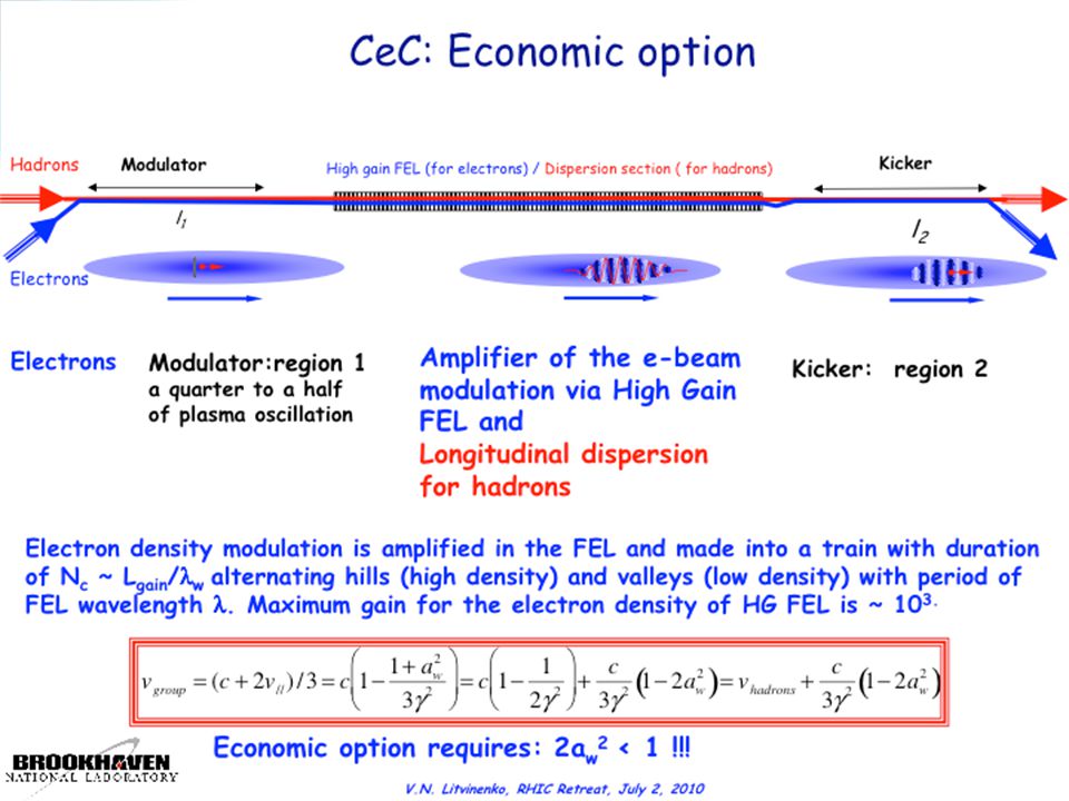
Amplifier of the e-beam modulation via High Gain FEL Longitudinal dispersion for hadrons Modulator: region 1 (a quarter to a half of plasma oscillation) Kicker: region 2 Electron density modulation is amplified in the FEL and made into a train with duration of N c ~ L gain / w alternating hills (high density) and valleys (low density) with period of FEL wavelength. Maximum gain for the electron density of HG FEL is ~ 10 3. Economic option requires: 2a w 2 < 1 !!! Modulator Kicker Electrons Hadrons l2l2 l1l1 High gain FEL (for electrons) / Dispersion section ( for hadrons) Coherent e- Cooling: Economic option Litvinenko & Derbenev, “Coherent Electron Cooling,” Phys. Rev. Lett. 102, 114801 (2009). V.N. Litvinenko, RHIC Retreat, July 2, 2010
 / Dispersion section ( for hadrons) Coherent e- Cooling: Economic option Litvinenko & Derbenev, Coherent Electron Cooling, Phys. Rev. Lett. 102, (2009). V.N. Litvinenko, RHIC Retreat, July 2,")
4
A multi-stage simulation effort: 1) Couple e- macro-particles from tracking code into VORPAL 2) Full 3D f-PIC simulations of the modulator (VORPAL) 3) Simulate e- response to ions, including the cases of finite beam size and multiple ions in idealized & non-ideal conditions 4) For each case, perform coupled GENESIS simulations of the FEL amplifier... 5)... followed by corresponding PIC simulations of kicker with VORPAL This talk: enabling proper 3D coupling from modulator to the FEL amplifier, so that all details of the 6D phase space coordinates are retained in the input distribution used in simulations of the amplifier
... followed by corresponding PIC simulations of kicker with VORPAL This talk: enabling proper 3D coupling from modulator to the FEL amplifier, so that all details of the 6D phase space coordinates are retained in the input distribution used in simulations of the amplifier.")
5
Coupling modulator results to FEL simulations: coupling VORPAL output to GENESIS input General scheme: –FEL amplifier in the linear regime => additive response –model one ion at a time (with a zero-noise quiet start) and separately simulate SASE signal starting from shot noise –in close analogy with stochastic cooling, the effects of coherent velocity drag accumulate linearly in t with multiple turns, while the larger single- pass contributions from noise accumulate more slowly as t 1/2 –coherent term determines the cooling time Coherent velocity perturbations: subtle effect, difficult to model by coupling f PIC and FEL (GENESIS) simulations We employ two independent approaches: –one based on inferring a distribution of local bunching parameters –the other based on the ‘clones’ technique
 and separately simulate SASE signal starting from shot noise –in close analogy with stochastic cooling, the effects of coherent velocity drag accumulate linearly in t with multiple turns, while the larger single- pass contributions from noise accumulate more slowly as t 1/2 –coherent term determines the cooling time Coherent velocity perturbations: subtle effect, difficult to model by coupling f PIC and FEL (GENESIS) simulations We employ two independent approaches: –one based on inferring a distribution of local bunching parameters –the other based on the ‘clones’ technique")
6
Modulator simulations using f PIC algorithm f PIC uses macro-particles to represent deviation from assumed equilibrium distribution –much quieter for simulation of beam or plasma perturbations –implemented in VORPAL for Maxwellian & Lorentzian velocities –20 cells per D, 200 ptcls/cell to accurately model temp. effects

7
Coupling modulator results to FEL simulations (coupling VORPAL output to GENESIS input) Convert f macro-particles to constant weight GENESIS particles GENESIS reads particle file –No coherent response to electron perturbations –Must define bunching coefficients and phases Get longitudinal bunching parameters from electron ponderomotive phases =(k FEL +k u )*z - ct*k FEL (pond. phase) – GENESIS divides slices of width FEL – Must specify bunching b for each slice – GENESIS modifies phase of each ptcl: '= - 2*|b|sin( -arg{b}) McNeil and Robb, J. Phys. D: Appl. Phys. 31, 371 (1998). Definition of bunching parameters:
 – GENESIS divides slices of width FEL – Must specify bunching b for each slice – GENESIS modifies phase of each ptcl: = - 2*|b|sin( -arg{b}) McNeil and Robb, J. Phys. D: Appl. Phys. 31, 371 (1998). Definition of bunching parameters:.")
8
Modulator output coupled into FEL simulations Before: Coupling of 3D e- perturbation from modulator was essentially 1D Two ions in the modulator Lasing provoked by two ionsFEL-amplified response in e- density distribution Right: New approach: compute 2D distribution of bunching parameters, use as input to GENESIS simulations of amplifier stage

9
Simulation results (GENESIS) Binned current (top) and p z (bottom), lab frame: growing bunching, as seen from phase shift Mean bunching as a function of z along the undulator: no saturation at exit from the wiggler FEL power distribution along the bunch, at exit from the undulator Magnitude of the bunching parameter along the bunch e - density after a single pass through the FEL, max(δn e )~5.3 10 16 m -3.
 Binned current (top) and p z (bottom), lab frame: growing bunching, as seen from phase shift Mean bunching as a function of z along the undulator: no saturation at exit from the wiggler FEL power distribution along the bunch, at exit from the undulator Magnitude of the bunching parameter along the bunch e - density after a single pass through the FEL, max(δn e )~ m -3.")
10
One fundamental difficulty of GENESIS bunching parameters is that they are derived from sums over the f macroparticles, and so the coupling is somehow indirect Another fundamental difficulty with GENESIS bunching parameters is that they capture coherent density perturbations, but not the velocity perturbations Use of clones [*] promises to remove both of these difficulties, plus it provides the very important possibility of benchmarking two different algorithms Correct statistics of shot noise, by construction * V.N. Litvinenko, “Macro-particle FEL model with self-consistent spontaneous radiation”, unpublished (2002) 3D coupling to FEL simulations: using ‘clone’ macroparticles
![One fundamental difficulty of GENESIS bunching parameters is that they are derived from sums over the f macroparticles, and so the coupling is somehow indirect Another fundamental difficulty with GENESIS bunching parameters is that they capture coherent density perturbations, but not the velocity perturbations Use of clones [*] promises to remove both of these difficulties, plus it provides the very important possibility of benchmarking two different algorithms Correct statistics of shot noise, by construction * V.N.](http://images.slideplayer.com/13/4158748/slides/slide_10.jpg "Litvinenko, Macro-particle FEL model with self-consistent spontaneous radiation , unpublished (2002) 3D coupling to FEL simulations: using ‘clone’ macroparticles.")
11
Present approach to control of shot noise Randomly distributed macroparticles yield artificially strong spontaneous radiation in FEL simulations, increasing shot noise by factor (N mp ) 1/2 –power of spontaneous radiation goes up by factor N mp Special seeding of macroparticles is used in GINGER and GENESIS –W.M. Fawley, PRST-AB 5, 070701 (2002). –2M macroparticles seeded at equal intervals within the fundamental wavelength λ 0 : –with zero bunching, correct spontaneous radiation through the M th harmonic of the λ 0 –physical shot noise & initial bunching are obtained by perturbing the initial phases, so that
. –2M macroparticles seeded at equal intervals within the fundamental wavelength λ 0 : –with zero bunching, correct spontaneous radiation through the M th harmonic of the λ 0 –physical shot noise & initial bunching are obtained by perturbing the initial phases, so that.")
12
Alternate idea of ‘clone’ macroparticles will enable direct 3D coupling from into FEL "positron" clone macroparticles are created for each electron, with precisely the same initial phase space coordinates –weight/charge of macro-particles are set as follows V.N. Litvinenko, unpublished (2002) In absence of FEL interaction, with sign of magnetic field switched, clone trajectories are identical to electron When = 0, including FEL interaction, initial shot noise is zero When = 1, physically correct shot noise is obtained – FEL interaction results in separation of electrons and clones – the bunching leads to induced radiation in the FEL Induced radiation for λ 0 and its odd harmonics is the same e-’s & clones – correct treatment of odd harmonics requires greater care – OK for purposes of CEC simulations and
 In absence of FEL interaction, with sign of magnetic field switched, clone trajectories are identical to electron When = 0, including FEL interaction, initial shot noise is zero When = 1, physically correct shot noise is obtained – FEL interaction results in separation of electrons and clones – the bunching leads to induced radiation in the FEL Induced radiation for λ 0 and its odd harmonics is the same e-’s & clones – correct treatment of odd harmonics requires greater care – OK for purposes of CEC simulations and.")
13
Complex-weight clone multiplets More generally, not just clone pairs, but complex weight multiplets can be constructed for modeling high harmonics, with To keep FEL equations correct Local 6D neutrality + density fluctuations: Exact power and spectrum of spontaneous radiation when Simple clone pairs :

14
Implementing particle-clone pairs approach in GENESIS Clone macroparticles have already been implemented –GENESIS procedures for overwriting the input distribution are bypassed, can use distributions generated by RNG (no need for Fawley’s algorithm) –pass all basic tests like no lasing when a perfect quiet start distribution is used Benchmarked clone-based simulations of SASE with RNG-generated distributions against GENESIS with internally generated distributions (with noise) –varied the number of particles per slice, used uncorrelated energy spread for comparison –agreement at the 10% level ( ~ 2.2 0.2 in clones runs compared to ~ 2.4 0.5 in original GENESIS –no N 1/2 dependence of growth rate on the number of simulation particles Longitudinal phase space at exit from the undulator in simulations with the original (red) and modified, clone-based (blue) versions of GENESIS
 –pass all basic tests like no lasing when a perfect quiet start distribution is used Benchmarked clone-based simulations of SASE with RNG-generated distributions against GENESIS with internally generated distributions (with noise) –varied the number of particles per slice, used uncorrelated energy spread for comparison –agreement at the 10% level ( ~ 2.2 0.2 in clones runs compared to ~ 2.4 0.5 in original GENESIS –no N 1/2 dependence of growth rate on the number of simulation particles Longitudinal phase space at exit from the undulator in simulations with the original (red) and modified, clone-based (blue) versions of GENESIS")
15
Work in progress and future plans Enabling direct coupling of the VORPAL δf simulation putput into the 3D distribution of particle- clone pairs Exploring the use of complex-weight clones for modeling high harmonics Careful comparisons of fully 3D amplifier simulations performed with the clone-based approach vs GENESIS simulations with distribution of bunching parameter as input More realistic simulations that account for the finite beam size and multiple ions; accounting for ion’s transverse velocity and modeling cooling for anisotropic plasmas

16
We thank I. Ben-Zvi and other members of the BNL Collider Accelerator Department for many useful discussions. We thank S. Reiche (PSI) for his assistance with coupling simulations into GENESIS. Work at Tech-X Corp. is supported by the US DOE Office of Science, Office of Nuclear Physics under grant No.’s DE-FG02-08ER85182, DE-SC0000835 and DE-FC02-07ER41499. We used computational resources of NERSC, BNL and Tech-X. Acknowledgments Boulder, Colorado USA
 for his assistance with coupling simulations into GENESIS. Work at Tech-X Corp. is supported by the US DOE Office of Science, Office of Nuclear Physics under grant No.’s DE-FG02-08ER85182, DE-SC and DE-FC02-07ER We used computational resources of NERSC, BNL and Tech-X. Acknowledgments Boulder, Colorado USA.")
19
Schematic of a Coherent electron Cooling (CeC) system: Modulator Kicker Dispersion section ( for hadrons) Electrons Hadrons l2l2 l1l1 High gain FEL (for electrons) EhEh E < E h E > E h EhEh E < E h E > E h Coherent Electron Cooling concept –uses FEL to combine electron & stochastic cooling concepts –a CEC system has three major subsystems modulator:the ions imprint a “density bump” on e- distribution amplifier:FEL interaction amplifies density bump by orders of magnitude kicker:the amplified & phase-shifted e- charge distribution is used to correct the velocity offset of the ions Litvinenko & Derbenev, “Coherent Electron Cooling,” Phys. Rev. Lett. 102, 114801 (2009).
..")
20
Modulator simulations use f PIC algorithm; run in parallel at NERSC f PIC uses macro-particles to represent deviation from assumed equilibrium distribution –much quieter for simulation of beam or plasma perturbations –implemented in VORPAL for Maxwellian & Lorentzian velocities Maximum simulation size –3D domain, 40 D on a side; 20 cells per D ~5 x 10 8 cells –200 ptcls/cell to accurately model temp. effects ~1 x 10 11 ptcls –dt ~ (dx/v th,x ) / 8; pe ~ v th / 2 ~1,000 time steps –1 s/ptcl/step ~30,000 processor-hours for ½ plasma period –~24 hours on ~1,000 proc’s; or ~30 minutes on ~60,000 proc’s
 / 8; pe ~ v th / 2 ~1,000 time steps –1 s/ptcl/step ~30,000 processor-hours for ½ plasma period –~24 hours on ~1,000 proc’s; or ~30 minutes on ~60,000 proc’s.")
Similar presentations


>")
