Download presentation
Presentation is loading. Please wait.

1
AAT Injector Nozzle Test Chamber P15681 Calibration Fluid Exhaust System Zach Huston, Hayden Cummings, Adam Farnung, Tim Nichols, Robert Moshier, Andrew Heuser

2
Agenda Updated Requirements Concept Generation Concept Selection Plan for Sub-System Design Phase Action Items

3
Customer Requirements

4
Engineering Requirements

5
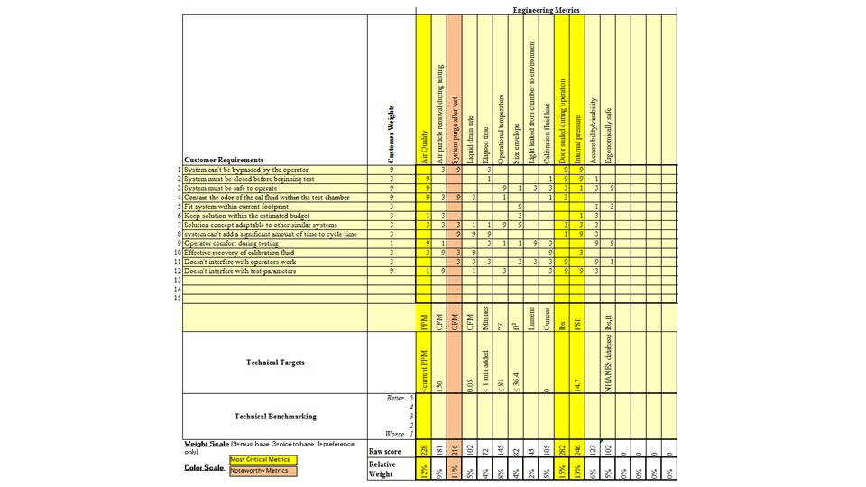
House of Quality

7
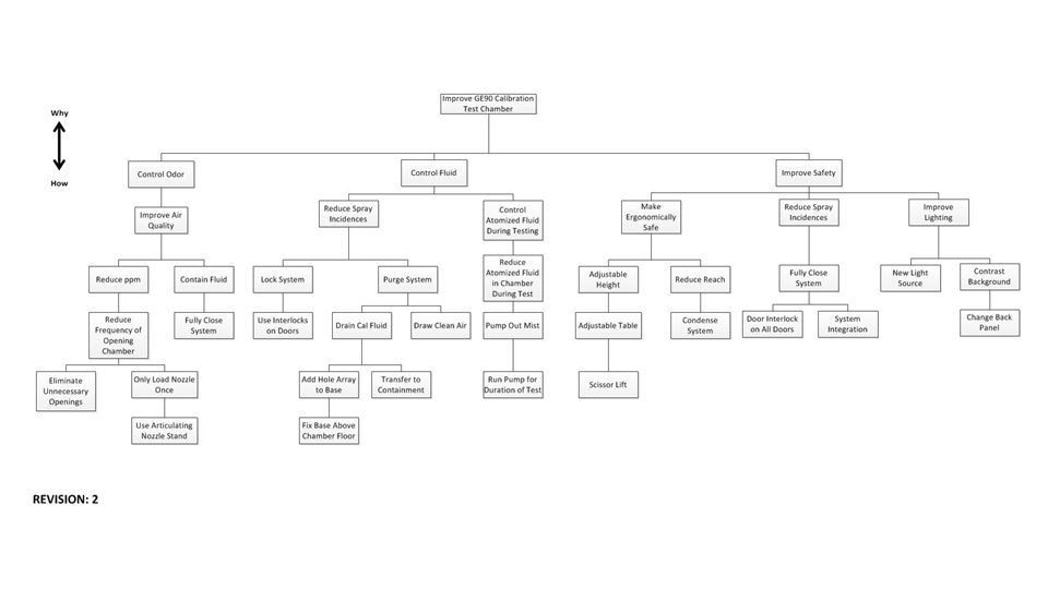
Functional Decomposition

9
System Architecture

10
Benchmarking No longer Feasible Potentially Feasible Feasible Option

11
Market Comparison Centrifugal vs. Blow/Pull Through Mist Collectors

12
Morphological Analysis

13
Pugh Matrix

14
Functional Pugh Chart Gloves in chamber best meet containment criteria Angle test requires additional analysis Laser can be eliminated from concept

15
Functional Pugh Chart Sub-basin best meets Liquid Drainage criteria LED light bar best meets Visibility criteria

16
Concept Generation Wanted to focus on Reducing the mist in the chamber Increasing the drainage rate Reduce operators fluid contact time

17
Initial Concepts – Reducing Mist Initial ideas were scrapped due to Time it could take to purge chamber fully The ability to capture all of the atomized fluid Internal components being in the way All components moving in unison

18
Increasing Drain Rate Key Features ●“False” or “Drop” floor ●Slots to allow for better drainage ●Angled basin to prevent pooling ●Angled to allow better drainage Things to keep in mind ●With more openings in the base - Weaker structurally using current material

19
Reducing Contact Time Key Features ●Sealed interlock - no direct contact with inside of chamber ●Glove holes for attached gloves ●Both testing done in 1 location ●Pump system only on interlock - can open inner door to have suction during testing Things to keep in mind ●Ergonomics of using the gloves - can they reach everything ●Ease of attaching nozzle to test fixture through gloves

20
Additional Ideas ●Improved lighting (LED) ●Contrast backdrop - easier visibility of angles ●Camera with defined allowable angles for spray
 ●Contrast backdrop - easier visibility of angles ●Camera with defined allowable angles for spray")
21
Concept Selection Key Features ●Interlock - top loaded ●Pump on interlock ●Bottom interlock door - opened for testing ●Glove hole for access to inside of chamber ●False floor - for increased drainage ●Angled basin - eliminates the pooling of liquid ●Camera with back drop and LED lighting Challenges ●Incorporating all fluid lines into the airlock ●Allowing enough slack to remove testing block for set up of the nozzle

22
Risk Assessment

23
Cycle Time Analysis

26
Feasibility Analysis Robert - Test Location Zach - Ergonomics Hayden - Test Visibility Tim - Purge Vacuum Adam - Purge Time Andrew - Make vs. Buy

27
Feasibility Analysis: Test Location Designing to a single location for all testing Looking at potential impact of changing flow test location Looking at potential new fixture designs to allow both tests Incorporating nozzle block off into angle test block

28
Feasibility Analysis – Ergonomics Current layout outside spectrum of acceptable work height New system height determined as a function of the link length proportion mannequin Assume operator performing light work

29
Feasibility Analysis: Ergonomics

30
Feasibility Analysis: Test Visibility Picture – with no vacuum, chamber becomes clouded and hard to see into Need to look at the maximum vacuum we can pull during testing Want to be able to maximize the visibility in the chamber Testing to be done (Trial and Error) to find the optimal vacuum needed Testing will answer the question if we want to pursue alternate ideas to increase visibility
 to find the optimal vacuum needed Testing will answer the question if we want to pursue alternate ideas to increase visibility")
31
Feasibility Analysis: Time vs. Chamber Size Need to address the time it could take to fully pump out a chamber of all air and fluid Need to be conscious of cycle time

32
Feasibility Analysis: Vacuum Feasibility

33
Feasibility Analysis: Make vs. Buy Address the issues of purchasing an item versus making it Need to evaluate specs of a purchased item versus specs of an item we can make Evaluate the need to meet specifications for given products Determine if the item will be bought or made

34
Project Schedule

35
Plan for Testing Baseline Test Procedure (“Control Group”) -Acquire test chamber from AAT -Acquire cal fluid (possibly used from their tests) -Acquire reject nozzle from AAT -Purchase pump -Find an adequate test location -Prepare testing setup including fluid reservoir, fluid pump, hoses,power supply, nozzle, and chamber. -Run Test for Original System: 1.Connect nozzle 2.Close and seal system (including upper cover) 3.Pump cal fluid through nozzle, into chamber 4.End test 5.Open front doors and (disconnect) remove nozzle 6.Take air ppm measurements
 3.Pump cal fluid through nozzle, into chamber 4.End test 5.Open front doors and (disconnect) remove nozzle 6.Take air ppm measurements.")
36
Plan for Testing Prototype Testing Procedure (Treatment Group) -Build our new test chamber -Find alternate testing location to avoid cross-contamination from “Control Group” -Prepare testing setup including fluid reservoir, fluid pump, hoses,power supply, nozzle, and new chamber. -Run Test for Prototype System: 1)Connect nozzle and mount inside of air lock 2)Close air lock 3)Through glove, open inner door of airlock 4)Pump cal fluid through nozzle, into chamber 5)End test 6)Through glove, close inner airlock door 7)Purge airlock 8)Open outer airlock door and (disconnect) remove nozzle 9)Take air ppm measurements
Connect nozzle and mount inside of air lock 2)Close air lock 3)Through glove, open inner door of airlock 4)Pump cal fluid through nozzle, into chamber 5)End test 6)Through glove, close inner airlock door 7)Purge airlock 8)Open outer airlock door and (disconnect) remove nozzle 9)Take air ppm measurements.")
37
Action Items Get system level design approved Team 10/1/14

Similar presentations


![© Copyright 2010 Dresser-Rand Gasket Cell Relocation [Revision: Feb 2011] Team Members: Cody Willmart, Aaron Marcotte, Jacky Li, Daniel Swol, Tyler Borden.](/19/5883807/big_thumb.jpg "© Copyright 2010 Dresser-Rand Gasket Cell Relocation [Revision: Feb 2011] Team Members: Cody Willmart, Aaron Marcotte, Jacky Li, Daniel Swol, Tyler Borden.>")