Download presentation
Presentation is loading. Please wait.

2
Experimental Methods in Catalysis (EMC) M.Tech-Catalysis Technology II Semester CT-503 Dr.K.R.Krishnamurthy National Centre for Catalysis Research Indian Institute of Technology Chennai-600036
 M.Tech-Catalysis Technology II Semester CT-503 Dr.K.R.Krishnamurthy National Centre for Catalysis Research Indian Institute of Technology Chennai")
3
Catalysts- Functionalities Basic Activity Selectivity Stability Applied Manufacturing Aging Deactivation Regenerability Evalua -tion Character -izattion Prepa -ration Catalyst Development Cycle Why do we Characterize? Provides answers to WHY & HOW Integral part of Catalyst development cycle

4
Catalysts-Characteristics Chemical composition Active elements, promoters, stabilizers Structural features Crystalline/Amorphous, Crystal structure Phase composition, Phase transformations- TiO 2— Anatase/Rutile Surface Properties Composition, -Bulk Vs Surface, in-situ techniques Co-ordination, Geometry/ Structure- Spectroscopic methods Dispersion & distribution of active phases Concentration profile, Crystallite size Electronic properties Redox character, Chemisorption Textural properties Surface area, Pore volume, Pore-size & distribution Physical properties Size, Shape, Strength Chemical properties Surface reactivity/Acidity/Basicity Enabling Structure-Activity correlations

5
Catalysts- Shape factor

6
Catalysts- Shape effect

7
Characterization of Catalysts PreparationCharacterizati on EvaluationAgeingSpent Concn. of active elements Phase composition In-situ Spectroscopy Solid state transformations Inactive phases Species in Solution phase Electronic stateTransient surface species Structural transformations Poisons Solid state transformations Structural featuresReactants & Products Surface composition Analysis of coke Preparation techniques Dispersion & Distribution Kinetics & mechanism Surface composition Evolve active phase Ensure desired characteristics Surface reactions Catalyst lifeDeactivation & Regeneration Catalysts Characterization- From Cradle to Coffin

8
Textural properties CatalystsAdsorbents Metals Metal oxides Metal sulfides Metal chlorides Zeolites Heteropoly acids Alumina Silica Carbon Mol.sieves Clays Surface area Pore structure Pore size-Area-Volume-Distribution-Geometry Textural properties Porous solids External Internal Geometric shape/size Porosity / Pores

9
Textural properties- Significance Surface area/Pore volume - Dispersion of active phase Pore size & distribution Molecular traffic-Diffusion of reactants & products Heat & mass transfer Diffusion rates- residence time Selectivity Extent of coking Thermal & mechanical stability Textural properties-Integral part of catalyst architecture

10
Origin of pores Crystal structure- Intrinsic voids A tomic/molecular Preparation- Voids due to leaving groups Hydroxides, carbonates, Oxalates- Ni(OH) 2, MgCO 3, ZnC 2 O 4 Structural modifications-Intercalation/Pillaring Graphite/ Clay Aggregation/Coalescence- Preparation Formation of secondary particles from primary particles Flexible pores- dispersion of particles Agglomeration/Sintering- Pre-treatments Rigid pores Compacting Shaping
 2, MgCO 3, ZnC 2 O 4 Structural modifications-Intercalation/Pillaring Graphite/ Clay Aggregation/Coalescence- Preparation Formation of secondary particles from primary particles Flexible pores- dispersion of particles Agglomeration/Sintering- Pre-treatments Rigid pores Compacting Shaping")
11
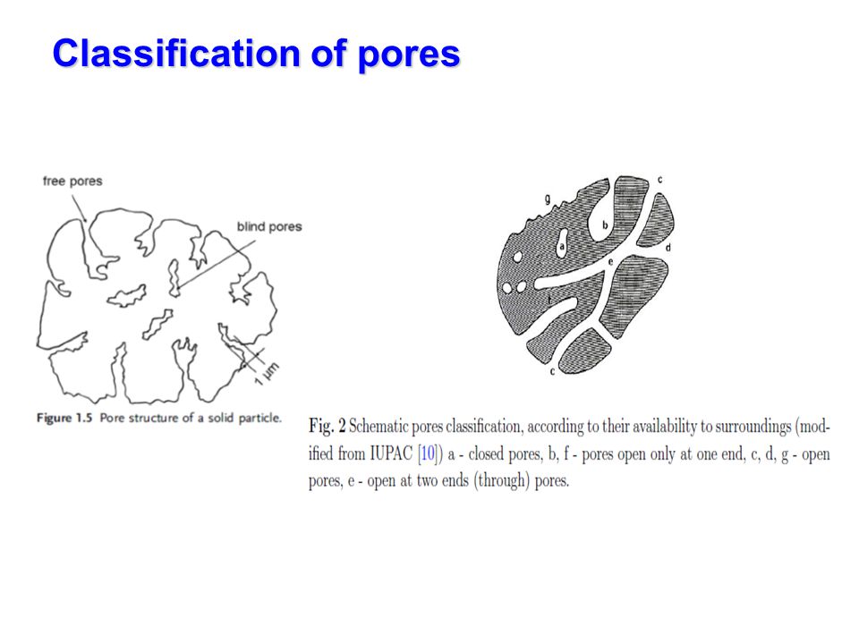
Origin of pores Pores Inherent in any solid structure Intrinsic intra particle pores Voids created by specific arrangement of atoms / molecules- Zeolites- Cages & channels –Structurally intrinsic pores Voids formed due to missing/removed molecules, atoms, particles- Dehydration of AlOOH to Al 2 O 3 Removal of Na from Na silicate glass Interstitial space between graphitic plates in CF Extrinsic intra particle pores Voids created by removal of combustible additives- Addition of surfactants-fillers in alumina precursor to increase pore volume/size

12
Origin & types of pores K.Kaneko,J.Membrane Science, 96,59,1994

13
Pore size% pore volume % surface area Micro30 - 60>95 Meso< 10< 5 Macro25 - 30negligible

14
Intrinsic pores in zeolites ME Davis, Nature,412,813, (2002)
")
15
Classification of pores

18
Experimental techniques

20
2015/5/4Aerosol & Particulate Research Lab 19 Definition The concentration of gases, liquids or dissolved substances (adsorbate) on the surface of solids (adsorbent) Physical Adsorption (van der Waals adsorption): weak bonding of gas molecules to the solid; exothermic (~ 0.1 Kcal/mole); reversible Chemisorption: chemical bonding by reaction; exothermic (10 Kcal/mole); irreversible Physical vs Chemical
 on the surface of solids (adsorbent) Physical Adsorption (van der Waals adsorption): weak bonding of gas molecules to the solid; exothermic (~ 0.1 Kcal/mole); reversible Chemisorption: chemical bonding by reaction; exothermic (10 Kcal/mole); irreversible Physical vs Chemical")
21
2015/5/4Aerosol & Particulate Research Lab 20 Sorbent Materials Activated Carbon Activated Alumina Air Pollution Engineering Manual., 1992 Silica Gel Molecular Sieves (zeolite) Polar and Non-polar adsorbents Properties of Activated Carbon Bulk Density22-34 lb/ft 3 Heat Capacity0.27-0.36 BTU/lb o F Pore Volume0.56-1.20 cm 3 /g Surface Area600-1600 m 2 /g Average Pore Diameter 15-25 Å Regeneration Temperature (Steaming) 100-140 o C Maximum Allowable Temperature 150 o C http://www.activatedcarbonindia.com/activate d_carbon.htm
 Polar and Non-polar adsorbents Properties of Activated Carbon Bulk Density22-34 lb/ft 3 Heat Capacity BTU/lb o F Pore Volume cm 3 /g Surface Area m 2 /g Average Pore Diameter Å Regeneration Temperature (Steaming) o C Maximum Allowable Temperature 150 o C d_carbon.htm")
22
2015/5/4Aerosol & Particulate Research Lab 21 Adsorption Mechanism

23
Measurement of Textural properties Adsorption isotherms- v = f (p/p o ) T Adsorbates – N 2 Ar, Kr Methods – Volumetric – static/dynamic- Manual/automated Gravimetric Samples to be pre-treated to remove adsorbed impurities/moisture Different molecules depending upon the size can be used as probes to elucidate pore structure - Molecular resolution porosimetry Isotherms/Isobars/Isosters – ( P,V,T)
 T Adsorbates – N 2 Ar, Kr Methods – Volumetric – static/dynamic- Manual/automated Gravimetric Samples to be pre-treated to remove adsorbed impurities/moisture Different molecules depending upon the size can be used as probes to elucidate pore structure - Molecular resolution porosimetry Isotherms/Isobars/Isosters – ( P,V,T)")
25
Measurement of adsorption

26
Types of adsorption isotherms -IUPAC Reveal the type of pores & degree of adsorbate-adsorbent interactions IUPAC classification – 6 types of isotherms Type-I - Microporous solids Langmuir isotherm Type-II - Multilayer adsorption on non-porous / macroporous solids Type-III - Adsorption on non-porous /macro- porous solids with weak adsorption Type-IV - Adsorption on meso porous solids with hysteresis loop Type-V - Same as IV type with weak adsorbate-adsorbent interaction Type-VI - Stepped adsorption isotherm, on different faces of solid Original classification by Brunauer covers upto Type-5

27
Types of Isotherms - Brunauer

28
Origin of Hysteresis Normally observed in Type IV & V and sometimes in II &III Absence of hysteresis- Type-I Micro porous structure At any given value for Va, p/p 0 for in desorption branch is lower than that on adsorption Chemical potential of adsorbate during desorption is lower; hence true equilibrium exists Differences in contact angle during ads/des may lead to hysteresis Presence of ink-bottle type pores-narrow neck & wide body. This could mean that adsorption branch represents equilibrium Differences in the shape of the meniscus in the case of cylindrical pores with both ends open

29
Types of hysteresis loops- de Boer

30
Hysteresis Loops IUPAC

31
Surface area by BET method p/v( p 0 -p) = 1/v m C + (C-1)p/ Cv m p 0 - Plot of p/v(p 0 -p) Vs p/p 0 P 0 - Sat. pressure; p- actual equilibrium Pressure; V m -mono layer volume V- adsorbed vol. at equilibrium pressure p C- constant signifying adsorbate-adsorbent extent of interaction Applicable in the range p/p 0 - 0.05-0.35 & Only from Type II &IV isotherms Surface heterogeneity and interactions between adsorbates in adsorbed state are not accounted for Slope + Intercept – 1/v m Surface area = v m N A m / 22414 x 10 -20 m 2 N- Avogadro’s number; A m -cross sectional area of adsorbate molecule Mono layer volume by Point B method in Type II isotherms

32
Pore geometries- models

33
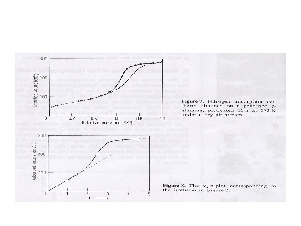
t- method of Lippens & deBoer Standard isotherms- Plot of V a /V m Vs p/p 0 gives a straight line t = 0.354( V a /V m ) = f 1 (p/p 0 ) – for multilayer adsorption of nitrogen t is independent of the nature of adsorbent if it is non-porous Plot of t Vs V a then passes through origin and the slope of the line can be used to calculate SA s t = 1.547 x 10 6 dV a /dt with t expressed in nm s t Surface area by t-method As long as multilayer adsorption takes place, V a –t plot is a straight line passing through origin At higher t values deviations occur; Upward deviation – capillary condensation, cylindrical pores, ink- bottle type, spheroidal cavities Downward deviation- micro pores, with slit shaped geometry Higher the pressure at which deviation occurs, the larger the pore size
 = f 1 (p/p 0 ) – for multilayer adsorption of nitrogen t is independent of the nature of adsorbent if it is non-porous Plot of t Vs V a then passes through origin and the slope of the line can be used to calculate SA s t = x 10 6 dV a /dt with t expressed in nm s t Surface area by t-method As long as multilayer adsorption takes place, V a –t plot is a straight line passing through origin At higher t values deviations occur; Upward deviation – capillary condensation, cylindrical pores, ink- bottle type, spheroidal cavities Downward deviation- micro pores, with slit shaped geometry Higher the pressure at which deviation occurs, the larger the pore size")
34
α s - method of Sing Comparison of experimental isotherm with that of standard one Thickness t replaced by a specific V a /V m ratio for non-porous solid Ratio of volume adsorbed at specific p/p 0 to volume adsorbed at p/p 0 = 0.4 is designated as α s α s = V a /V m = f(p/p 0 ) ; α s = 1 at p/p 0 =0.4 Basis - mono layer coverage completed and multilayer adsn. starts at p/p 0 = 0.4

35
t - Plots for various pore size ranges

36
Pore size distribution- BJH method Based on Kelvin equation for capillary condensation for spherical meniscus lnp/p 0 = -2vλ Cosθ/ r k RT –θ- contact angle –λ- surface tension –r k - Kelvin radius –V-molar volume With θ =0, γ = 8.85.dynes/cm2 V= 34.6 cc/mole r k = 4.14/ln(p/p 0 ) t = 3.5[5/ln(p/p 0 )] 1/3 Pore radius r p = r k + t rprprprp rkrkrkrk t Model calculations For cylindrical pores - Gregg & Sing – p.164 For parallel plates - RB Anderson - p.66
![Pore size distribution- BJH method Based on Kelvin equation for capillary condensation for spherical meniscus lnp/p 0 = -2vλ Cosθ/ r k RT –θ- contact angle –λ- surface tension –r k - Kelvin radius –V-molar volume With θ =0, γ = 8.85.dynes/cm2 V= 34.6 cc/mole r k = 4.14/ln(p/p 0 ) t = 3.5[5/ln(p/p 0 )] 1/3 Pore radius r p = r k + t rprprprp rkrkrkrk t Model calculations For cylindrical pores - Gregg & Sing – p.164 For parallel plates - RB Anderson - p.66](http://images.slideplayer.com/13/4142436/slides/slide_36.jpg "Pore size distribution- BJH method Based on Kelvin equation for capillary condensation for spherical meniscus lnp/p 0 = -2vλ Cosθ/ r k RT –θ- contact angle –λ- surface tension –r k - Kelvin radius –V-molar volume With θ =0, γ = 8.85.dynes/cm2 V= 34.6 cc/mole r k = 4.14/ln(p/p 0 ) t = 3.5[5/ln(p/p 0 )] 1/3 Pore radius r p = r k + t rprprprp rkrkrkrk t Model calculations For cylindrical pores - Gregg & Sing – p.164 For parallel plates - RB Anderson - p.66")
37
Calculation of t, r k & r p

39
dV = dv f +dv k dV k = dV-dV f dV f = 0.064xΔtx ∑dS p dS p = 31.2 dV p /r* p dV p = dV k (r* p /r* k )
")
40
Micro porous solids Follow Type I isotherm- Langmuir isotherm Large uptake of adsorbate at very low pressures, up to p/p 0 =0.15 BET model applicable up to pores 1 nm For <1nm Dubinin model applicable Dubinin- Radushhkevich equation for micro porous solids log 10 V a = log 10 V 0 - D( log 10 X) 2 V a - Vol adsorbed per unit mass of adsorbent V 0 – largest volume of adsorbate, total pore volume X- p/p 0 ; D- factor varying with temp & asorbent/adsorbate Langmuir equation 1/n = 1/n m + 1/(n m K) X 1/p/p 0 n- moles adsorbed per gram of adsorbent; n m - monolayer volume Plot of 1/n.Vs. 1/p/p 0 gives a straight line with intercept 1/n m Surface area can be calculated from n m Total pore volume from the uptake at horizontal plateau

45
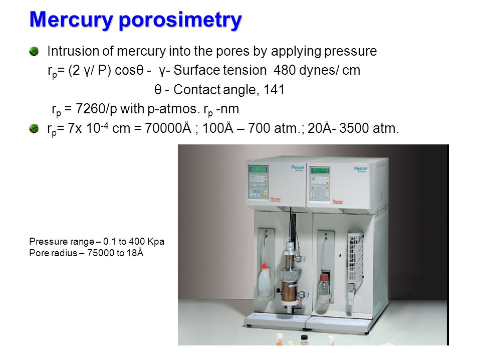
Mercury porosimetry Intrusion of mercury into the pores by applying pressure r p = (2 γ/ P) cosθ - γ- Surface tension 480 dynes/ cm θ - Contact angle, 141 r p = 7260/p with p-atmos. r p -nm r p = 7x 10 -4 cm = 70000Å ; 100Å – 700 atm.; 20Å- 3500 atm. Pressure range – 0.1 to 400 Kpa Pore radius – 75000 to 18Å

47
Pore structure Analysis - Summary Adsorption Isotherm BET Plot Isotherm Type Pore size distribution Hysteresis Type t-Curve Surface area area Pore radius/ Pore volume Pore type, Shape, Geometry

Similar presentations


 ions from aqueous solution effluent using Melamine-Formaldehyde-DTPA resin in a fixed-bed up-flow column By Ahmad Baraka Supervisors.>")


>")
 Dr/Marwa Abdelfattah Fall 2013-2014.>")