Download presentation
Presentation is loading. Please wait.

2
Plan and design adequate drainage Types of drainage systems Purpose of adequate drainage Maintaining a drainage system

3
Terminal Learning Objectives Enabling Learning Objectives

4
Lecture method Power point Demonstration Practical application

5
Written exam

6
Classroom Instruction No safety concerns for this period of instruction Inclement weather plan Fire exit plan

7
Are there any questions concerning: What will be taught? How it will be taught? How the student will be evaluated?

8
Precipitation Interception Infiltration Ground Water

9
Rain Fall Snow Fall/Melt Humidity

10
Interception is the process of vegetation absorbing the water before it reaches the soil. Once the holding capacity of the vegetation has been reached, the soil will then start receiving water.

11
Infiltration is the waters ability to penetrate the soil surface. The following factors affect the process of infiltration: Vegetation presence or lack there of. Soil type. (some soil types retain water more than others.) Slope of terrain.
 Slope of terrain..")
12
Surface water: Surface water is retained in the top soil. (depended upon vegetation and soil type.) Sub-surface water: Water that is present below the ground. (water table). Capillary water: The water that seeps to the surface.
 Sub-surface water: Water that is present below the ground. (water table). Capillary water: The water that seeps to the surface..")
13
Any questions? Questions for you!!

14
Methods of estimating water runoff Hasty Field Estimate

15
The hasty method is used when an existing stream crosses or interferes with your construction site. Certain measures must be taken to avoid possible water damage to your construction site. Using the following formula, we can determine the “Area of Waterway” (AW)
.")
16
AW = WI + W2 x H 2 AW = Area of the waterway W1 = Width of the channel bottom W2 = Width at the high water mark H = Height from the bottom to the high water mark

17
W2 W1 HT

18
ADES = 2AW ADES = Design cross section 2 = Safety Factor AW = Area of the waterway that was previously computed

19
7 + 9 x 4 = 32 Sqft (AW) 2 32 Sqft x 2 = 64 Sqft (Ades)
 2 32 Sqft x 2 = 64 Sqft (Ades)")
20
5 + 7 x 3 = 18 Sqft (AW) 2 18 Sqft x 2 = 36 Sqft (Ades)
 2 18 Sqft x 2 = 36 Sqft (Ades)")
22
Review handouts #1 and #2 Take a Break

23
The field estimate method is used to estimate the peak volume of storm water runoff. Results of this method are adequate for determining the size of drainage structures for temporary drainage in areas of 100 acres or less.

24
Q = 2 x A x R x C Q = peak volume of storm water runoff, in cubic feet per second 2 = safety factor (constant) A = area of drainage basin, in acres R = design rainfall intensity based on the one hour, two year frequency rainstorm, in inches per hour C = coefficient representing a ration of runoff to rainfall
 A = area of drainage basin, in acres R = design rainfall intensity based on the one hour, two year frequency rainstorm, in inches per hour C = coefficient representing a ration of runoff to rainfall")
25
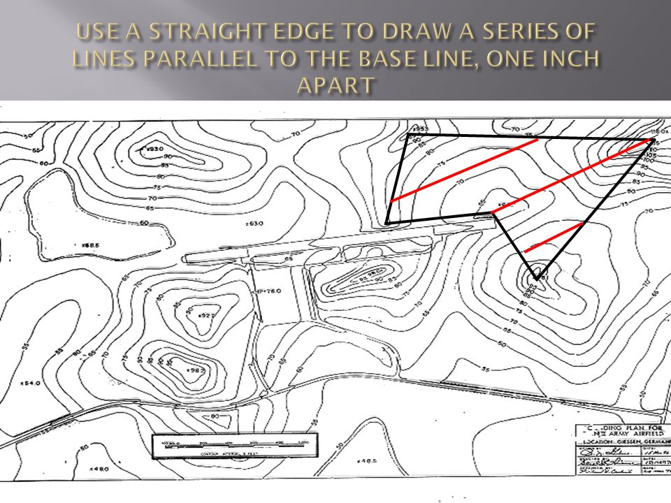
The fastest and most preferred method for determining the size of the drainage area is the stripper method The first step is called delineation. (Done on a topographic map)
.")
31
Measure the length of each line in the drainage area. Add all the lengths together This is the map area in square inches 2.12” + 2.62” +.50” = 5.25 square inches 2.12” 2.62”.50”

32
For a more accurate determination, you can draw the lines ¼” or ½” apart from the base line. If ¼” spacing is used, you must take total length of lines and divide by 4. If ½” spacing is used, you must take total length of lines and divide by 2.

33
Determine how many feet are in one inch on the map. Example: MAP Scale: 1 : 5,000 5000 ÷ 12 = 416.67 ft. 1 inch on the map is 416.67 ft

34
Determine how many square feet are in one square inch on the map. 416.67² = 173,613.88 One square inch on a map contains 173,613.88 square feet on the ground

35
Total square feet in the drainage area? 5.25” x 173,613.88 = 911,472.87 SqFt Now convert square feet to acres. 911,472.87 ÷ 43,560 = 20.92 or A = 21 acres

36
Q = 2 x A x R x C A = 21 Q = 2 x 21 x R x C

37
Example on page 6 of the student handout Follow along with the demonstration

38
Perform the Practical Exercise Worksheet #1

40
The Project is in Eastern North Carolina It falls between 1.5 and 2.0, always use the larger number. Formula Q = 2 x 21 x 2 x C

41
The ratio of runoff to rainfall. The amount of water expected to drain from an area as the result of a specific amount of rainfall. It is expressed as a decimal. There are three primary factors that affect the percentage; Soil type Surface cover slope

42
Porous soil - A large portion of the soil will infiltrate leading to a smaller runoff coefficient Man made surfaces – Like asphalt, concrete, and compacted gravel or macadam will result in a higher runoff coefficient

43
To use table 6-1, you need to understand the following terms Without Turf – Is ground that is completely bare With Turf – Is ground that is covered with vegetation. If the area has some vegetation but is not completely covered, use the higher without turf value

44
As terrain becomes steeper, water flows sooner and more rapidly. This allows less time for infiltration to occur and results in the C value becoming larger for the natural cover or soil categories.

45
Use the Unified Soil Classification System (USCS) to select the PREDOMINANT soil type. This will be needed for the left column of table 6-1 (the next slide). If the area is wooded or covered with asphalt, concrete, gravel or macadam simply lookup the “C” value in the left hand column.
. If the area is wooded or covered with asphalt, concrete, gravel or macadam simply lookup the C value in the left hand column..")
47
Indentify the slope on the map. Find the difference from the top to the bottom of the slope

48
180 160 140 120 100 181 B 100 A Elevation B =181m Elevation A =100m Difference in 81m elevation (Vd) Horizontal =4150m Distance 81_ 4150 X 100 =1.9% Slope Vd Hd X100= % of Slope
 Horizontal =4150m Distance 81_ 4150 X 100 =1.9% Slope Vd Hd X100= % of Slope")
49
TURF: If the soil is not covered, determine whether the area is with or without turf SAFETY: In all cases where you have more than one possible runoff coefficient, use the highest value

50
Soil or Cover Classification C VALUES Slope 2 & 7% w/turf turf w/turf turf w/turf turf w/o w/o w/o GW, GP, SW, SP.10.20.15.25.20.30 GMd, SMd, ML,.30.40.35.45.40.50 MH, Pt GMu, GC, SMu, SC.55.65.60.70.65.75 CL, OL, CH, OH Wooded area.20.20.20.20.20.20 Asphalt Pavement.95.95.95 Concrete.90.90.90 Pavement Gravel/macadam.70.70.70

51
Your drainage area is made up of ML soil, with 49% turf and a slope of 2%. Looking at Table 6-1 you should come up with 0.40. Now in final formula from The Answer : Q = 2 x 21 x 2 x.40 Q = 33.6 CFS

52
Expedient culvert and ditch design is based on the waterway area. The hasty method deals with waterway area. The field estimate method deals with peak volume of storm water runoff (Q).
..")
53
Q = PEAK VOLUME OF STORM WATER RUNOFF V = VELOCITY OF WATER, IN FEET PER SECOND (FPS) Aw = WATERWAY AREA, IN SQUARE FEET Q = VAw
 Aw = WATERWAY AREA, IN SQUARE FEET Q = VAw")
54
For expedient purposes, you will always use a velocity of 4 fps for design of expedient drainage structures. Example Q = V x Aw (divide both sides by V) The Results are: Q ÷ V = Aw (Using the previous calculation from your handout of 33.6 cfs) Final answer 33.6 (cfs) ÷ 4 (constant) = 8.4 sqft (Aw, Area of waterway)
 The Results are: Q ÷ V = Aw (Using the previous calculation from your handout of 33.6 cfs) Final answer 33.6 (cfs) ÷ 4 (constant) = 8.4 sqft (Aw, Area of waterway).")
55
As with the hasty method, you rarely design a drainage system to flow completely full. You must apply a safety factor (Ades) Ades = 2 x Aw Ades = 2 x 8.4 Ades = 16.8 sqft
 Ades = 2 x Aw Ades = 2 x 8.4 Ades = 16.8 sqft.")
59
Triangular (V) ditches are used to move small amounts of water. Q ≤ 60 cfs or Aw ≤ 15 sqft
 ditches are used to move small amounts of water. Q ≤ 60 cfs or Aw ≤ 15 sqft")
60
SYMMETRICAL Both sides of the ditch are inclined equally NON_SYMMETRICAL Each side of the ditch are inclined differently Ensure the appropriate side-slope ratio is selected to serve its designed purpose. If the side walls are too step it invites excessive corrosion and ditch clogging.

61
Ditches have two sloped sides, with each having a respective slope ratio. This is expressed as horizontal feet to vertical feet. Example: 3 : 1 is a side slope of 3 feet horizontal to a 1 foot vertical. (1:1) (3:1)
 (3:1).")
62
The sidewall of a ditch located adjacent to the shoulder is called the front slope of the ditch. The far slope, called the back slope, is simple an extension of the cut face of the excavation. BACK SLOPEFRONT SLOPE ROAD

63
D = Ca x 2 X + Y + 0.5 D = Ditch depth in feet. Rounded to two decimal places. Ca = Channel area computed previously. X =Horizontal run of the front slope ratio. Y = Horizontal run of the back slope ratio. 0.5 = Safety factor constant. (1/2 foot freeboard)
.")
64
Ditch Width: W = D x (X + Y) W = Ditch width in feet. Rounded to two decimal places. D = Ditch depth in feet. X = Front slope ratio. Y = Back slope ratio.

65
Using your previous Ades of 16.8 sqft and a front slope of 3 : 1 and a back slope 1 : 1, calculate the depth and width of the ditch. D = 16.8 + 0.5W = D x (X +Y) 3+1 W = 2.55' x (3 + 1) D = 16.8 + 0.5 4W = 2.55 x 4 D = 4.2 + 0.5 W = 10.20’ D = 2.05 + 0.5 D = 2.55’
 3+1 W = 2.55 x (3 + 1) D = W = 2.55 x 4 D = W = 10.20’ D = D = 2.55’.")
66
Triangular Ditch Calculations Worksheet

67
Installed for larger runoff requirements, usually 60 cfps / 15 aw or greater. The designer of the ditch determines the bottom width based upon the cutting edge of the equipment used. DEPTH OF WATER WIDTH OF DITCH CUTTING DEPTH.5 FT FREE BOARD

68
Ditch Depth: D = Aw + 0.5 W D = Ditch Depth in feet. Rounded to two decimals Ca = Channel area in square feet. W = Width of ditch (bottom) in feet. 0.5 = Safety factor constant. (1/2 foot of freeboard)
 in feet. 0.5 = Safety factor constant. (1/2 foot of freeboard).")
69
With an AW of 18.75, using a D7G to excavate the ditch, determine the ditch depth. 18.75 aw ÷ 7.25’ (D7 width) +.5 (freeboard) = 3.1’ deep
 +.5 (freeboard) = 3.1’ deep.")
70
Trapezodial Ditch worksheet

72
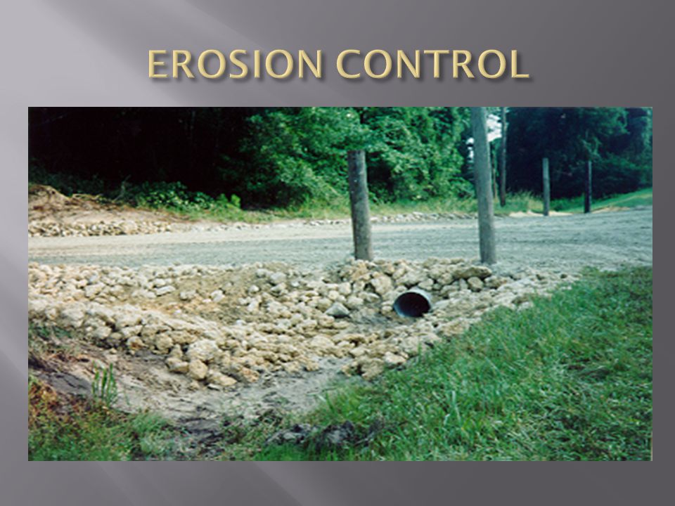
There are several methods of erosion control. The desirable gradient for a ditch is between 05 and 2%. Ditches larger than 2% will require erosion control. Examples: Ditch Linings Check Dams

73
May be lined to prevent erosion. Examples: Concrete Asphalt Rock Mortor Does not decrease the flow but protects the soil. Expensive and not always readily available Grass Protects the soil, slow the flow and is cheap

76
Constructed with 6-8” diameter timbers. Set 2’ into the sides of the ditch. Weir notch is 6” deep and a minimum of 12” long. 4’ of rock apron for every 1’ of dam height. The top of the check dam should be at the high water mark, when high water mark is not visible, place check dam 1’ below the top of the ditch.

78
Will have a minimum spacing of 50 feet. Should be placed as far apart as possible, while achieving the desired gradient. Spacing Calculations: S = 100 (H) A – B S = Dam Spacing 100 = Constant H = Height of Dam A = Present Slope B = Desired Slope
 A – B S = Dam Spacing 100 = Constant H = Height of Dam A = Present Slope B = Desired Slope.")
79
What spacing will be needed for a 4’ high check dam with a 10% slope. S = 4 x 100 10 – 2 S = 50’

81
Two classifications Permanent (refer back to the Military Roads class) Expedient Different types of material used Corrugated metal Concrete Vitrified Clay (VC) Polyvinyl Chloride (PVC) Timber Ect.
 Expedient Different types of material used Corrugated metal Concrete Vitrified Clay (VC) Polyvinyl Chloride (PVC) Timber Ect.")
82
Timber Box Good workmanship Large timber Strong enough to support heaviest vehicle traffic Minimum of 12” cover Corrugated Metal Pipe Culvert (CMP) 8”-72” diameter Shipped in 26” long half sections Bolted in every hole
 diameter Shipped in 26 long half sections Bolted in every hole")
83
Concrete pipe Comes in any size Comes in different shapes (circle, square, etc) Overall strength Smooth interior surface Higher amount of water flow Transportation considerations
 Overall strength Smooth interior surface Higher amount of water flow Transportation considerations")
84
Permanent culverts are selected based on their diameter. There are two maximum diameter (Dmax) equations. Fills greater than 36 inches Dmax = 2/3 x F Fills less then 36 inches Dmax = F - 12
 equations. Fills greater than 36 inches Dmax = 2/3 x F Fills less then 36 inches Dmax = F")
85
Dmax = 2/3 x Fill Dmax = Maximum culvert diameter in inches rounded to two decimal places. 2/3 = A constant that represents the minimum fill depth required for the maximum diameter of culvert to be calculated. Fill = Fill depth in inches rounded to two decimal places.

88
Dmax = 2/3 x F F = 6’ x 12” = 72” Dmax = 2/3 x 72” Dmax = 48 inches

89
Complete the DMAX worksheet

90
Several Factors Economical Diameter Number of pipe required Culvert Length Order Length

91
You want to save material. Put in the least amount of culverts. They need to equal or exceed the design area. Manpower requirements

92
To find the most economical size, you must divide the design area by the end area of several different pipe sizes. Use the largest pipe that satisfies the fill and cover requirements as a starting point. Work your way down in size until the amount of pipes needed changes. Once changed, we have reached and passed our optimal design. Go back to the prior number and pipe demision.

93
N = Ades PEA N = Number of Pipes Ades = Design Cross Section PEA = Pipe End Area, cross sectional end area of culvert in ft squared

94
Maximum Diameter (“)Cross Sectional Area (sqft) 12” -------------------------------------- 00.79 sqft 18” -------------------------------------- 01.77 sqft 24” -------------------------------------- 03.14 sqft 30” -------------------------------------- 04.91 sqft 36” -------------------------------------- 07.07 sqft 42” -------------------------------------- 09.62 sqft 48” -------------------------------------- 12.57 sqft 60” -------------------------------------- 19.64 sqft 72” -------------------------------------- 28.27 sqft
Cross Sectional Area (sqft) sqft sqft sqft sqft sqft sqft sqft sqft sqft")
95
N48” = Ades ÷ A48 N48” = 17.5 ÷ 12.57 = 1.4 or 2 N48” = (2) 48” Pipes N42” = Ades ÷ A42 N42” = 17.5 ÷ 9.62 = 1.8 or 2 N42” = (2) 42” Pipes N36” = Ades ÷ A36 N36” = 17.5 ÷ 7.07 = 2.5 or 3 N36” = (3) 36” Pipes
 48 Pipes N42 = Ades ÷ A42 N42 = 17.5 ÷ 9.62 = 1.8 or 2 N42 = (2) 42 Pipes N36 = Ades ÷ A36 N36 = 17.5 ÷ 7.07 = 2.5 or 3 N36 = (3) 36 Pipes")
96
( DL x SL ) + R OADWAY WIDTH + ( DR x SR ) = CL Culvert Length Note: After calculating culvert length, ensure you round up to an even number. Now that we’ve determined that we will need (2) 42” diameter culverts, we must now calculate the culvert length. Use the following formula to do so:
 42 diameter culverts, we must now calculate the culvert length. Use the following formula to do so:.")
97
CL = ( 7 x 2 ) + 22’ + ( 6 x 3 ) CL = 14’ + 22” + 18’ CL = 54’ + 2’ ( no headwalls on the exhaust end) CL = 56’ ORDER FORMULA OL (order length) = CL x # of pipes x 1.15 (waste) OL = ( 56’ X 2 ) 1.15 OL = ( 112 ) 1.15 OL = 128.8’ or 130’ of pipe needed
 + 22’ + ( 6 x 3 ) CL = 14’ ’ CL = 54’ + 2’ ( no headwalls on the exhaust end) CL = 56’ ORDER FORMULA OL (order length) = CL x # of pipes x 1.15 (waste) OL = ( 56’ X 2 ) 1.15 OL = ( 112 ) 1.15 OL = 128.8’ or 130’ of pipe needed")
99
HEADWALL

100
EXHUAST WITHOUT HEADWALL

Similar presentations


 Below you see a cross-section of a ditch. It runs parallel to a 200-acre field consisting of permanent pasture.>")

