Download presentation
Presentation is loading. Please wait.

1
Topic 11: Wave phenomena

3
11.1 Standing (stationary) waves 11.1.1 Describe the nature of standing (stationary) waves. Students should consider energy transfer, amplitude and phase.

4
Formation of standing waves

5
The reflected wave is 180º phase shifted

6
How do the incident and reflected waves superimpose?

7
Reflection from fixed or free end

9
Boundary conditions on a string Click to play Pulse

10
Boundary conditions for a wave Click to play

11
Standing wave

14
Standing wave

16
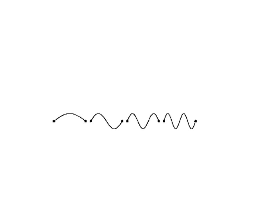
Nodes and antinodes λ Hyperlink

17
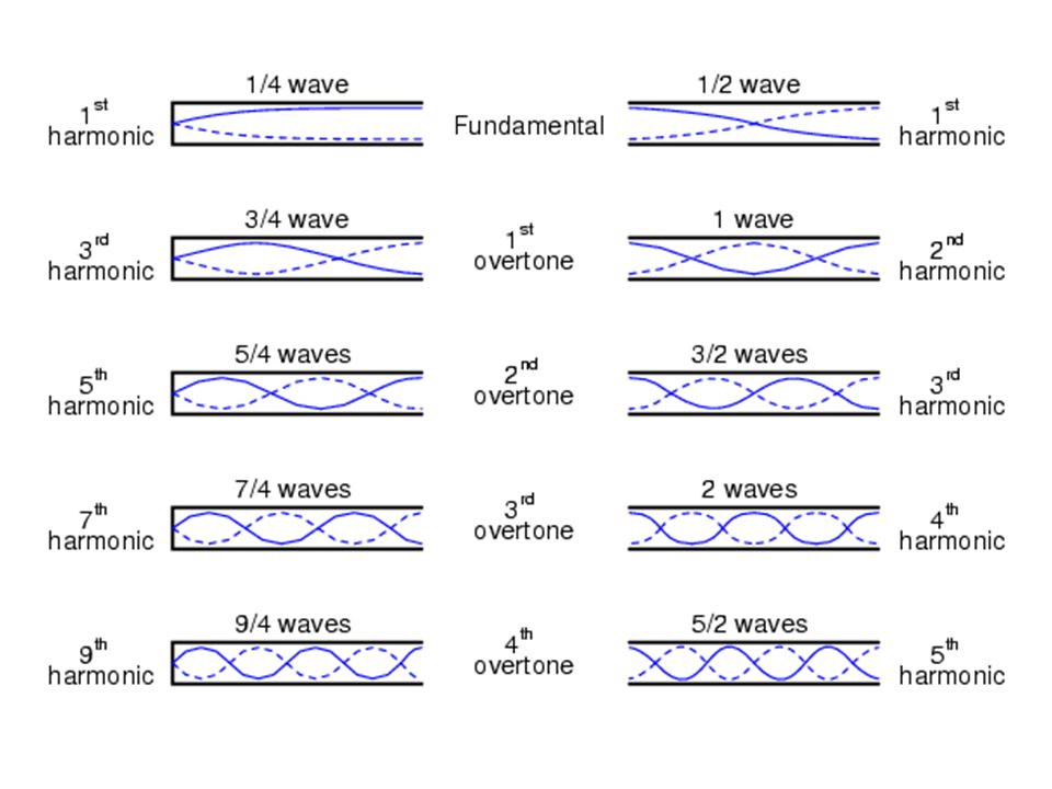
Modes of vibration in strings λ λ Hyperlink

19
Standing waves on a string Click to play Fixed / free Free / free Fixed / fixed

20
Set up this experiment and produce the first 8 standing waves. Record the wavelength for each one. Record the frequency for each resonant standing wave. Plot a suitable graph to determine the relationship between frequency and wavelength.

21
Modes of vibration in pipes Closed pipe i.e. node at one end and antinode at the other Open pipe i.e. Antinode at both ends. Hyperlink

22
Nodes and antinodes

23
Nodes and Antinodes

25
A 0.3 m section of discarded garden hose will produce a trumpet sound when blown as one blows a trumpet. Changing the length will change the pitch of the "trumpet".

27
Measurement of velocity of sound 1.Measure difference in length between 2 successive resonances. 2. Use this distance to calculate the wavelength. 3.Use this value and the frequency of the tuning fork to calculate the speed of sound.

29
http://www.physics.uc.edu/~sitko/CollegePhysicsIII/

30
Questions from Hamper page 134 Q’s 15,16.

32
Hyperlink

33
Stationary waveTraveling wave Amplitude Frequency Wavelength Phase Energy Complete the table

34
Stationary waveTraveling wave AmplitudeAll points have different amplitudes. Maximum at the antinodes. All points have the same amplitude. FrequencySame for all points on the wave. WavelengthDouble the distance between 2 nodes.Distance between 2 successive points in phase. PhaseAll points between 2 nodes are in phase.All points along 1 wavelength have a different phase. EnergyEnergy is not transmitted by the wave, but contained within it. Energy is transmitted by the wave.

35
Questions from Tsokos Page 256 Questions 1 – 6,8,10-14.

37
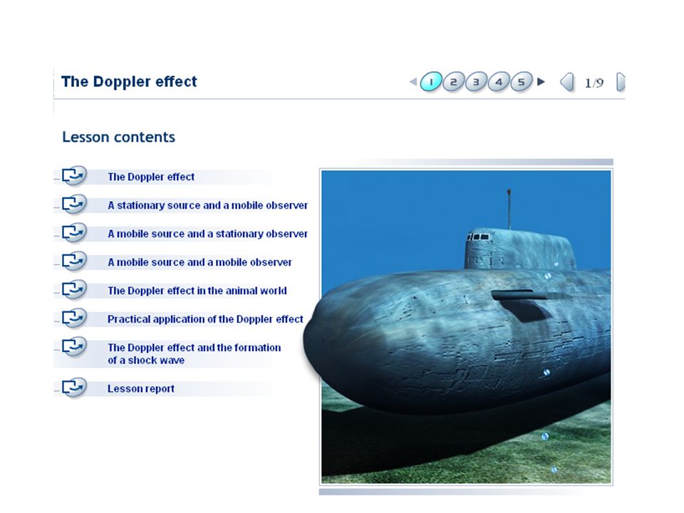
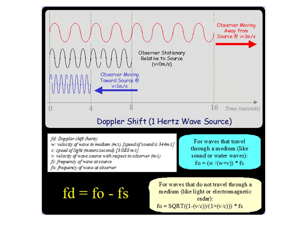
The Doppler effect The diagram below represents waves emitted by a source of sound, S, which is stationary relative to the air. The velocity of the sound waves relative to the air is v. Johann Christian Doppler 1803-1853

39
Doppler wavefronts Click to play

40
Doppler hyperlink

42
Which gives you the most chocolates?

44
Explain the Doppler effect by reference to wavefront diagrams for moving-detector and moving-source situations.

45
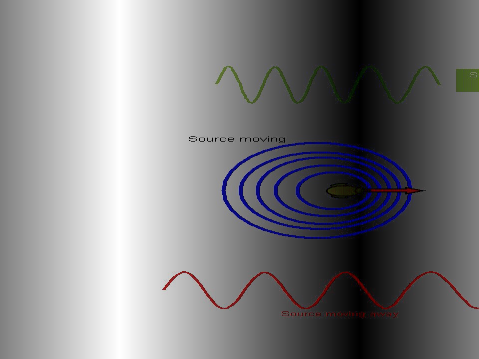
The next diagram represents waves emitted by a source which is moving (with velocity v s ) relative to the air. Motion of the source produces a change in the wavelength, longer wavelength behind, shorter wavelength in front of source. λ λ Speed same, frequency and wavelength change

46
Doppler effect for sound Hyperlink

47
Doppler effect for sound with moving observer

48
Moving observer Wavelength fixed, speed and frequency change

50
Doppler shift for SOUND source Be careful to apply the + or – the correct way.

51
Doppler sound problems

52
Answers

53
Questions Tsokos page 248 Q’s 1-7 Hamper page 136 Q’s 17-19.

54
Solve problems on the Doppler effect for electromagnetic waves using the approximation Students should appreciate that the approximation may be used only when v << c.

55
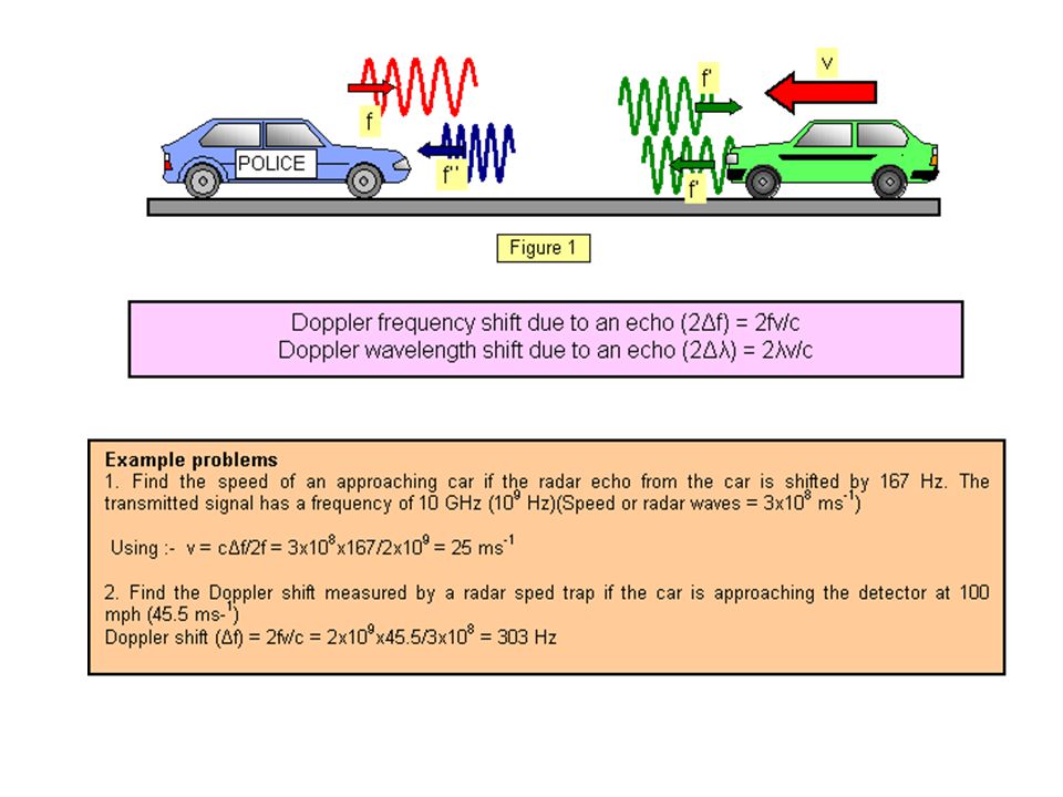
Caught by the fuzz. Take the case of the car and the radar speed trap. The emitted frequency of the police radar gun is f, the car acts like a moving observer receiving it at f'. It reflects it back at f', acting now as a moving source and the police receive it back shifted once again as f''. The total change in frequency (f'' - f) is therefore doubled.
 is therefore doubled..")
58
It can be shown that the relative Doppler shift for electro- magnetic radiations like light, radio waves etc is given (approximately) by where c is the speed of light and v is the relative speed of source and observer. The speed of a car is being measured by a police-person using a "radar speed-measuring gun". The frequency of the transmitted signal is 5GHz. When "mixed" the transmitted and received signals beat with a frequency of 750Hz. If the speed limit for the road is 110kmh -1, should the driver be fined or not? Question

59
Adding colour

60
Analysing blood flow

61
Questions Hamper page 138 Q’s 20-22.

62
11.3 Diffraction Sketch the variation with angle of diffraction of the relative intensity of light diffracted at a single slit. Hyperlink

65
Because of Huygen’s Principle, light passing through barriers do not continue as straight plane waves as in (a), but as spherical waves as in (b). This spreading out is called diffraction. Diffraction

66
Even a single slit can produce interference! This occurs because light waves from one part of the slit can interfere with light waves from another part of the slit.

67
Hyperlink

68
Single Aperture Diffraction Pattern Effect of slit width Single Aperture Diffraction Pattern: Narrower Aperture

69
Effect of wavelength θ =λ/b θ =2λ/b

70
Derive the formula

71
If the path difference between rays from C and A to a point on a distant screen is λ, then the path difference between rays from A and B is λ/2. There will therefore be destructive interference between light from A and light from B. From the diagram, it is clear that Now consider the aperture to be made up of pairs of point sources, A and B, A’ and B’, etc, as shown in the next diagram. Light from all these pairs of points will also interfere destructively

72
As the angles are small, we can write

73
Red light from a laser is passed through a single narrow slit, as shown in Figure 1. A pattern of bright and dark regions can be observed on the screen which is placed several metres beyond the slit. (a) The pattern on the screen may be represented as a graph of intensity against distance along the screen. The graph has been started in outline in Figure 2. The central bright region is already shown. Complete this graph to represent the rest of the pattern by drawing on Figure 2. (b) State the effect on the pattern if each of the following changes is made separately. (i) The width of the narrow slit is reduced (ii) With the original slit width, the intense red source is replaced with an intense source of green light. IB Question
 The pattern on the screen may be represented as a graph of intensity against distance along the screen. The graph has been started in outline in Figure 2. The central bright region is already shown. Complete this graph to represent the rest of the pattern by drawing on Figure 2. (b) State the effect on the pattern if each of the following changes is made separately. (i) The width of the narrow slit is reduced (ii) With the original slit width, the intense red source is replaced with an intense source of green light. IB Question.")
74
Questions Hamper page 141 Q’s 23,24 Tsokos page 265 Q’s 1-3a.

75
11.4 Resolution 2 objects can just be resolved when the maximum of 1 peak aligns with the minimum of the second peak

77
Resolution by separation of sources Click to play

78
Resolution depending on aperture Click to play

79
Resolution depending on wavelength Click to play

80
Circular apperture

81
Diffraction/interference patterns When the maxima in an interference pattern (or from two light sources) are too close together, it cannot be determined that there are actually two sources…thus it would be “unresolved” Hyperlink
 are too close together, it cannot be determined that there are actually two sources…thus it would be unresolved Hyperlink")
82
2 objects to be resolved b D L θ=L/D

83
The camera of a spy satellite orbiting at 200. km above the ground has a diameter of 35.0 cm. What is the smallest distance this camera can resolve on the surface of the Earth? (Assume an average wavelength of 500. nm for visible light) Problem
 Problem.")
84
The headlights of a car are 2.00 m apart. The pupil of the human eye has a diameter of about 2.0 mm. Suppose that light of wavelength 500. nm is being used. What is the maximum distance at which the two headlights are seen as distinct?

85
The pupil of the human eye has a diameter of about 2.0 mm and the distance between the pupil and the back of the eye (the retina) where the image is formed is about 20. mm. Suppose the eye uses light of wavelength 500 nm. Use this information to estimate the distance between the receptors in the eye.

86
Questions Hamper page 143 Q’s 25,26,27. Tsokos page 270 Q’s 1-4.

87
Describe the significance of resolution in the development of devices such as CDs and DVDs, the electron microscope and radio telescopes. What limits the resolution of a microscope, DVD, or telescope?

88
11.5 Polarisation Consider a single wave of light: If you looked at it “end on” it might look like this: And lots of them might look like this:

90
Plane polarised e.m. wave

91
Plane polarised wave Click to play

92
Describe what is meant by polarized light.

94
Polarisation Hyperlink

96
State and apply Brewster’s law. Φ For a particular angle Φ, the beam is completely plane-polarised, Brewster found that where n is the refractive index of the material

98
Polarising Filter Hamper page 145 Q’s 28,29. Picture has hyperlink

99
Polarisation of microwaves

100
Explain the terms polariser and analyser. Hyperlink

101
Hamper page 146 Q 30 A beam of unpolarized light can be thought of as containing a uniform mixture of linear polarizations at all possible angles. Since the average value of cos 2 θ is 1/2, the transmission coefficient becomes 2I 0 2I 0 = I 0

102
Calculate the intensity of a transmitted beam of polarized light using Malus’ law. 2I 0

103
Optical activity Some materials can rotate the plane of polarisation of light as it passes through them. The liquid crystals used in calculator displays, digital watches and lap top computer screens are also optically active. The amount of rotation in these crystals can also be altered by applying an electric field between the two faces of the screen and this is how the display is turned from bright to dark.Fig1.

104
The polarimeter The specific rotation of a given liquid may be found using a polarimeter as shown in Figure 2. The two polaroids are adjusted to give a minimum light intensity, and the scale reading noted. A measured length of solution of known concentration is then placed in the inner tube and the polaroids readjusted to regain a minimum and the scale is read again. The rotation of the plane of polarization of the light by the solution may then be found from the difference in the two scale readings. Describe the use of polarization in the determination of the concentration of certain solutions.

105
POLARIMETER h polariser analyser liquid

106
Certain solutions rotate the plane of polarisation of light passing through them. The angle through which the plane of polarisation is rotated depends on the concentration of the solution. Measuring the concentration of solutions Hamper page 148 Q31.

107
Outline qualitatively how polarisation may be used in stress analysis. The first photograph below shows a small part of a plastic set square viewed under normal conditions The next photograph shows the same object when placed between crossed polaroids

108
Liquid crystal displays The screen of an LCD TV is made of millions of liquid crystals. Each crystal is like the shutter of a camera either blocking the light or allowing it to pass through. You can control the amount of light that passes through by applying a voltage to a crystal or pixel. It does this by rotating the plane of polarisation of the light. A much-simplified diagram of this action is shown in Figure 1.

110
Questions Hamper page 149 practice questions 4-8. Tsokos page 278 Q’s 1-4,7,11,17,18,19.

Similar presentations