Download presentation
Presentation is loading. Please wait.

2
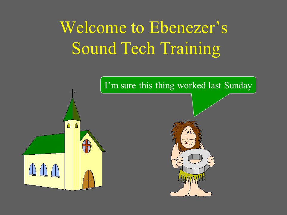
Welcome to Ebenezer’s Sound Tech Training I’m sure this thing worked last Sunday

3
The Importance of Acoustics What did he say?

4
REVERBERATION The Effects of Too Much REVERBERATION Impacts spoken word more than music. Impacts those with hearing loss the most. Makes certain words difficult to understand. Causes listener fatigue.

5
REVERBERATION How To Control REVERBERATION Use construction techniques which minimize reflections. Aim speakers to focus sound away from ceiling and walls. Use equalization to reduce frequencies which naturally resonate in the room.

6
As A Sound Tech,Your Biggest Mistake is Adding Too Much Bass

7
Or having stage monitor levels set too high The congregation needs to listen to the main speakers, not the monitors!

8
Always Check out the system before the service…. Mixer controls set normal. Mikes connected and working. Instruments connected and working. Monitor speakers aimed correctly. Wireless batteries in good condition. Service tape loaded and ready to go.

9
Two minutes prior to start of service is NOT the ideal time to begin a trouble-shooting process! Mark

10
POWERING UP THE SYSTEM ON FIRSTOFF FIRST Avoid damaging “POPS” - always turn power on or off in the order indicated!

11
NEVER CONNECT OR DISCONNECT MICROPHONES OR INSTRUMENTS…. Unless the channels are muted or the system is off. Pops, clicks, and buzzes can damage speakers!

12
Small round shielded cable for instruments Large flat unshielded cable for speakers Always use the right cable!

13
Examining Signal Flow

14
It All Starts Here… Mixer DI Box

15
The Big Picture Mixer From Signal Sources EQ CONTROLLER Stereo Amp EQ Monitor Speakers Main Speakers 70 Volt Amp Class Speakers 70 Volt Amp Fold-back Speaker AUX-1 AUX-2 MAIN Tannoy Bogen Peavey Tannoy Yamaha Mackie

16
Class Speakers actually consist of... Two speakers in the Narthex. A speaker in the nursery. A speaker in each of the young kids rooms. A speaker in the kitchen. Each room has its own volume control located in the room.

17
DON’T MESS WITH THE GRAPHIC EQUALIZERS! You can cause real problems with the system. Setting them requires the proper test equipment!

18
The Mackie SR24-4 Mixing Console

19
TWO IMPORTANT SWITCHES Master PowerPhantom Power Both must be on at all times! Mixer Rear Panel, lower left corner

20
What is Phantom Power? Low voltage applied to the mike lines by the mixer. Used to power electret mikes and active direct boxes. If the switch is off, choir mikes, podium mike and Peavey direct boxes will be dead.

21
The Mono Channel Strip Learn one and you know all twenty. Signal Flow Top to Bottom

22
The TRIM control The first stop for the signal at the mixer. Sets the overall level of the signal going to the rest of the mixer circuitry. Compensates for differing levels of various input devices. Proper setting is essential to low noise and ample “head room”.

23
TRIM Control Warning! If the red OL light comes on then your trim control is set too high! TURN DOWN THAT TRIM!

24
What is ample HEAD ROOM? No, its not having enough rest rooms on a ship!

25
Clip Noise Normal Signal Level Head Room Time

26
Clip Noise Normal Signal Level Time Clipping Clipping Causes Distortion…..

27
…..and distortion can blow your speakers! Yikes!

28
Hard Feedback Can Toast your speakers too If you go “ouch” after that last squeal, chances are so did your speakers!

29
and so can pops, clicks, and buzzes caused by plugging/unplugging hot mikes or instruments! Always mute the channel at the mixer first!

30
Ways to set the TRIM Control The Traditional Way…. Back down from clipping and hope for the best. Or….. TRIM?

31
The MACKIE Way sets the gain structure accurately by using the VU meter lights Channel SOLO button down. SOLO MODE in Pre-fade (Up). Adjust TRIM for zero on the VU Meter.
. Adjust TRIM for zero on the VU Meter..")
32
The AUX 1 Control Controls how much channel signal is sent to the stage monitor speakers. Always Pre-Fade, which means it is …. not affected by the channel EQ. not affected by the PAN control. not affected by the channel fader. affected by the MUTE control.

33
AUX 1 (Monitor) Rule Never mix choir mikes into the stage monitors! Feedback will be too difficult to control. I wish I hadn’t done that!

34
The AUX 2 Control Controls how much channel signal is sent to the stage fold-back speaker. Like AUX 1, it is always Pre-Fade. Used to send voice to the front edge of the stage. Speaker does not have the frequency range to handle music.

35
The AUX 3 Control You get a break - we don’t use it!

36
The AUX 4 Control Controls how much channel signal is sent to the CD/TAPE machine for recording. Used in post-fade mode (PRE button up) so that the signal…. Is controlled by the channel fader. Is processed by the channel EQ. Is affected by the PAN control. Is affected by the MUTE control.
 so that the signal…. Is controlled by the channel fader. Is processed by the channel EQ. Is affected by the PAN control. Is affected by the MUTE control..")
37
. Please make sure the PRE button is out. This places AUX 3 and AUX 4 in the post-fader mode.

38
The AUX 5 Control Controls how much channel signal is sent to the SERVICE TAPE MACHINE. Always post-fader. Today’s Sermon

39
The AUX 6 Control Controls how much channel signal is sent to the VCR. Always post-fader. Joe’s Rental Video

40
The Channel EQ Controls Make minor adjustments to tone quality of the channel. Does not affect monitor or fold-back speakers. Straight up (U) is flat (no EQ). For microphones always cut, never add.
 is flat (no EQ). For microphones always cut, never add..")
41
Use EQ Sparingly! One or two tick marks is usually enough. U EQ

42
On Microphone Channels Always cut, never add EQ It avoids feedback

43
The HI EQ Control Controls High Frequencies Too much high - cut a little

44
The LOW EQ Control Controls Low Frequencies Too much bass - cut a little

45
The MID and FREQ EQ Controls Work Together MID controls the amount of add or cut. FREQ controls the frequency to be added or cut. Set MID then sweep FREQ to get the desired effect.

46
If you get confused….. Just put the EQ knobs to their center positions. The system should sound acceptable with the EQ flat.

47
. The LOW CUT button reduces very low frequencies. Depress it to reduce handling and wind noise on hand-held, wireless and pulpit mikes. Leave it up for choir mikes and instruments.

48
Now lets take a look at the Mackie video…. and learn more about how EQ works Note: The mixer in the video is different than ours but it demonstrates the concept of EQ very well.

49
The Graph you’ll see on the video…. Frequency Volume BassTreble 20 Hz20,000 Hz

51
Mackie Video Review…. We have only one mid EQ covering 100 Hz to 8 KHz. Our bandwidth is fixed at 1.5 octaves so there is no bandwidth control. The concept is the same as in the video. The HI and LOW EQ are the same. The LOW CUT filter is the same.

52
Continuing with our SR24-4….

53
The PAN Control Since we combine the mixers left and right stereo channels into a single monaural output, the PAN controls do nothing. Simply leave the PAN controls centered.

54
The Red OL Light You’re Clipping! TURN DOWN THE TRIM!

55
The Green Signal Light You have signal - all is well….

56
The MUTE Button The only way to completely disable an input…. Always mute unused microphones. Always mute before connecting or disconnecting input devices.

57
The SOLO Button Sends the channel to headphones and VU meter. Good for troubleshooting. Used to set TRIM control. Can be used to set mix.

58
The L-R Button If you don’t assign the channel to a BUSS, the signal won’t go anywhere! For simplicity, always assign to the main L-R buss. Signal Buss Company

59
The FADER Control Controls how much signal goes to L-R and Post-Fade AUX outputs. Used to set mix into main speakers. Usually falls near “U” mark if TRIM is set properly.

60
Now you know how to control 20 of the 24 channels Only 4 more to go!

61
The Stereo Channels Channels 21 and 22 are combined. Channels 23 and 24 are combined. Used to combine stereo output from tape and CD machines. The only difference from mono channels is in EQ and use of the PAN control.

62
The EQ Differences Instead of swept EQ for the mid range, channels 21/22 and 23/24 have separate HI MID and LOW MID controls. Set these for the desired effect just like you do for the HI and LOW EQ controls.

63
Special PAN Control use Normally set to center. For Kids Choir split-track tapes pan left or right to send only the music track to main speaker while voice and music tracks go to monitor speakers.

64
Now for the output side of the mixer. Don’t let it scare you - we don’t use most of it!

65
There are 6 AUX SEND MASTERS One for each buss. Remember…. 1 - Stage monitors. 2 - Fold-back monitor. 3 - Not used. 4 - CD/Tape. 5 - Service tape recorder. 6 - VCR record.

66
The channel AUX determines how much signal gets on the buss. The AUX SEND MASTER determines how much signal gets off the buss. Channel AUXAUX SEND Signal Buss Company

67
Need more keyboard in the monitor mix - turn up AUX 1 on the keyboard channel. Need more of everything in the monitor mix - turn up the AUX 1 SEND MASTER.

68
Each AUX SEND has a SOLO button. Want to hear what’s going to the monitor speakers? Press the AUX 1 Send Master SOLO button. You’ll hear the whole mix. The VU Meter also reads the level of the signal going to the monitor speakers while the SOLO button is pressed.

69
The VU Level Meter Used to measure signal levels. Main L/R Output if no solo buttons pressed. Channel Signal when a solo button is pressed.

70
The RUDE SOLO Light Flashes to warn you when the VU meter is reading a SOLO channel signal, rather than the main L-R signal.

71
The SOLO LEVEL Sets the level of signal coming over the solo buss. Normally, set it about half way (U).
..")
72
The SOLO MODE Determines if the individual channel solo is taken before or after the fader control. Normally left in the post fade AFL (down) position. Exception when setting TRIM controls.
 position. Exception when setting TRIM controls..")
73
Pressing TAPE RETURN TO PHONES will kill all headphone output. Pressing TAPE RETURN TO MAIN MIX will kill all main speaker output. Never Press These!!! Disappearing Sound

74
PHONES/C-R LEVEL Adjust for a comfortable headphone level. Note: C-R stands for Control Room.

75
MAIN MIX FADER Adjusts the overall level going to the main and classroom speakers.

76
TALKBACK Push MAIN MIX for main speakers Push AUX 1&2 for stage and foldback speakers Sends console mike to main, stage, and foldback speakers. Sound Tech can talk to Choir Director during rehearsals. Adjust talkback level here

77
Now for some accessory items….

78
Dynamic Microphones General purpose hand-held. Working range 3 to 6 inches. Good for solos and small groups. Low output - trim above 3/4 full. Requires no phantom power from mixer.

79
Electret Microphones Condenser element with built-in preamp. Requires phantom power from mixer. Used for choir and pulpit. Sensitive - working range 2 feet or more. Exhibit bass when you get too close. High output - Trim set between 1/4 and 1/2 full.

80
Wireless Microphones There are two wireless receivers. There are three wireless microphones…. One receiver works with a lapel mike. One receiver works with the other lapel mike OR the hand-held wireless mike, never both!

81
Use only name brand alkaline or lithium batteries in the wireless mikes! Neveready discount battery I’m sorry

82
The Telex Wireless Receivers Diversity Light Signal Light

83
The Telex Wireless Receivers Diversity Light Signal Light Signal light indicates RF signal received. Diversity changes orange/green to indicate antenna receiving the best signal.

84
The Diversity Receiver AB Reflective Surface Multipath Signal Direct Signal Direct and Multipath signals cancel at antenna B. Receiver picks antenna A which still has a good signal.

85
Receiver Squelch Control Not a normal sound tech adjustment. Located on the rear of the receiver. Cuts receiver off to prevent “hiss” when no RF signal is present. If set too high, sound will chop off as mike is moved about. If set too low, “hiss” will be present when transmitter is turned off.

86
Observe the 3 to 1 Rule for Microphone Placement 3 FT 1 FT The distance between microphones is at least 3 times the distance between the singer and his microphone.

87
Why the 3 to 1 Rule? Minimizes picking up the same sound with multiple microphones. Minimizes Comb Filtering effect which…. Often causes a “hollow” sound. Causes sound to change with movement.

88
When two or more microphones pick up the same sound source from different distances, Comb-Filtering is the result. Due to the difference in sound travel time, certain frequencies cancel when combined at the mixer. Comb-Filtering makes the signal sound “hollow”

89
FrequencyBassTreble Volume Comb-Filtering…. “like the teeth of a comb”

90
Choir Microphone Placement 6 - 9 FT Always use the minimum number of mikes necessary to cover the area.

91
Position the Choir Mikes 6 to 9 feet apart. 2 to 3 feet in front of the front choir row. 2 to 3 feet above the heads of the last row. Pointing at the last row. 2-3 FT

92
Always Point Mikes at the Sound Source Mikes are more directional at high frequencies so they exhibit more bass off-axis. Like this Never like this

93
Keep the number of open mikes to a minimum…. It improves gain before feedback. It reduces noise and reverberation pickup. It minimizes comb-filtering effects. Never use two when one will do!

94
The Pro Co DB-1 Direct Box Also known as a “DI” Box. The most versatile. Takes Instrument, Line, or Speaker Level Inputs. Converts them to microphone level. Has a HI-CUT filter for speaker inputs. Has a ground-lift switch to reduce hum.

95
The Pro Co DB-1 Direct Box Also known as a “DI” Box LO-Z XLR Output Instrument or Speaker Input Instrument or Speaker Output to System

96
The Pro Co DB-1 Direct Box Ground/Lift Switch Hi-Cut/Flat Switch Speaker/Instrument Switch

97
The Peavey Direct Box Active - requires phantom power from the mixer. Has the best frequency response. Takes only line and instrument level inputs. Converts them to microphone level outputs. Simple to use - no switches to set. Peavey is the first choice unless you need the versatile features of the Pro Co.

98
The Peavey EDB-1 Direct Box Hi-Z Input from Instrument Lo-Z XLR Output to System Only two connections are needed Power Light DI Box

99
In-Line Transformer Small and easy to use. Good only for instruments such as guitars. Transformer

100
The Shure In-Line Transformer

101
The Headset Monitor Adapter Volume Plug to monitor speaker Used for the drummer

102
The Service Tape Machine Record Level VU Meter Tape SpeedNormally used for recording

103
Don’t use DOLBY on Church Recordings You never know if the person playing it back will have the Dolby capability. If you don’t use Dolby to record then the tape is good to play back on any machine.

104
Make sure the Tape Speed is centered during recording!! Tape Speed centered Dolby and the Dolby is off..…or Speed Fixed

105
To Queue a Tape, next song…. Press Music Search >>

106
To Queue a Tape, repeat song…. Press Music Search <<

107
The CD/TAPE Unit CD Track Select CD ControlsTape Controls Normally used for playback

108
The CD/TAPE Unit Output Switch to MIX position or their will be no output from the CD!

109
Make sure the tape speed is centered during recording!! Tape Speed Dolby and the Dolby switch is off.

110
The CD/TAPE Unit Single to play only selected track. Continuous to play selected track forward. Single..Cont

111
To Queue a CD Track.... 2. Press Queue 3. Press Track Number (use +10 for tracks greater than 9) 4. Press Play 1. Select Single or Continuous
 4. Press Play 1. Select Single or Continuous.")
112
To Queue a Tape, next song…. Play and Fast Forward Simultaneously Press….

113
To Queue a Tape, repeat song…. Play and Rewind Simultaneously Press….

114
What is a Split-Track Tape? A special choir tape with voices on one channel and accompaniment on the other. Using the Split-Track tape switch, you can play back voices, accompaniment, or both. Generally, use both during practice sessions and accompaniment during the performance.

115
Split Track Tape Switch RECORD LEFT L + R RIGHT CD-TAPESERVICE RECORDER HEADSET Selects record or playback of left only, right only, or left and right channels. Headset is for monitoring mixer. This switch prevents the possibility of a feed-back loop during record.

116
You can send music and voice to the monitors with music only to the main speakers. Good to help out the kids choir. Switch to L + R position. Pan mixer channel hard left or right to select music only for the main speakers. Remember - choir mikes will pick up some voice from the monitors.

117
The Cable Test Box 123 A good way to check for defective cables….

118
Never Connect Anything but Cables to the Test Box! I love it when they do that. Microphone Sales Guy

119
To check any 3-wire cable Mike cables with 3-pin XLR connectors 1/4-inch Tip Ring Sleeve (TRS) connectors Press button #1 and light #1 comes on Press button #2 and light #2 comes on Press button #3 and light #3 comes on
 connectors Press button #1 and light #1 comes on Press button #2 and light #2 comes on Press button #3 and light #3 comes on")
120
To check any 2-wire cable 1/4-inch Tip Sleeve (TS) connector Press button #1 - lights #1 and #3 come on Press button #2 - light #2 comes on Press button #3 - lights #1 and #3 come on
 connector Press button #1 - lights #1 and #3 come on Press button #2 - light #2 comes on Press button #3 - lights #1 and #3 come on")
121
Now a word about Video…. JOHN

122
Video System Wiring VCR Scan Converter Switch RF Modulator Amp Splitter TV Audio to Mixer Audio from Mixer Computer StageConsole Cart

123
The Master Power Switch for the Video Monitors…. is located in the electric closet

124
As a Sound Man you will normally only operate the VCR Make sure the VCR/COMPUTER switch is in the VCR position. Make sure the monitors are turned on and set to channel 3. Push play on the VCR. Un-mute and adjust the VCR channel level on the mixer for the desired volume.

125
We’ve made it Sound Man! He’s finally done!

Similar presentations


>")

 Overdubbing Mixdown.>")


 Phono Jack or Stereo Jack- 1/8 Also called a “Mini”>")
