Download presentation
Presentation is loading. Please wait.

1
Batura A.S., Orynyak I.V. IPS NASU Pisarenko’ Institute for Problems of Strength, Kyiv, Ukraine National Academy of Sciences of Ukraine Pisarenko’ Institute for Problems of Strength, Kyiv, Ukraine National Academy of Sciences of Ukraine ENGINEERING METHODS FOR STRESS INTENSITY FACTOR CALCULATION FOR 2-D AND 3-D BODIES WITH CRACKS

2
IPS NASU Weight Function Method for plane bodies - weight function, - the law of stress distribution, G – geometry parameters. - asymptotical (singular) part of WF, - correction (regular) part of WF. Then for any specified stress law(for example) obtain where and doesn’t depend upon geometry.
 part of WF, - correction (regular) part of WF. Then for any specified stress law(for example) obtain where and doesn’t depend upon geometry..")
3
IPS NASU Weight Function Method for plane bodies In particular, for a plane body with an edge crack The main idea of Weight Function Methods: If we have the SIF solution for one particular loading we can obtain the SIF solution for any other law of loading.

4
IPS NASU Application of WFM for a pipes In the circular pipe additional force N and moment M appear. Angle and displacement discontinuity can be expressed in the next form: Crack compliance method (modification of Cheng & Finnie approach) where Y N, Y M – are the dimensionless SIF, induced by M and N as in the plane body,
 where Y N, Y M – are the dimensionless SIF, induced by M and N as in the plane body,.")
5
IPS NASU Application of WFM for a pipes Crack compliance method (modification of Cheng & Finnie approach) - caused by loading,- caused by force, - caused by moment. Obtain result SIF : SIF is smaller than in the case of straight plane ! Using equilibrium equations for a ring and initial parameter method, get the expression for a dimensionless SIF decrease from the case of straight plane (Y 0 ): where - dimensionless pressure.
: where - dimensionless pressure..")
6
IPS NASU Application of WFM for a pipes Crack compliance method (modification of Cheng & Finnie approach) Result plots Conclusion: Advanced SIF formula for pipes was obtained. The feature of the SIF decreasing at rising of the pressure was found.

7
IPS NASU Weight Function Method for 3-D bodies (1) (2) - elliptical crack, - for semi- elliptical crack, - for quarter-elliptical crack -correction part - asymptotical part for elliptical crack.
 (2) - elliptical crack, - for semi- elliptical crack, - for quarter-elliptical crack -correction part - asymptotical part for elliptical crack.")
8
IPS NASU Weight Function Method for 3-D bodies geometry dependent loading dependent If is known we obtain and can calculate for any law of loading. where - is a known SIF for any law of loading. Similarly to the 2-D case, So

9
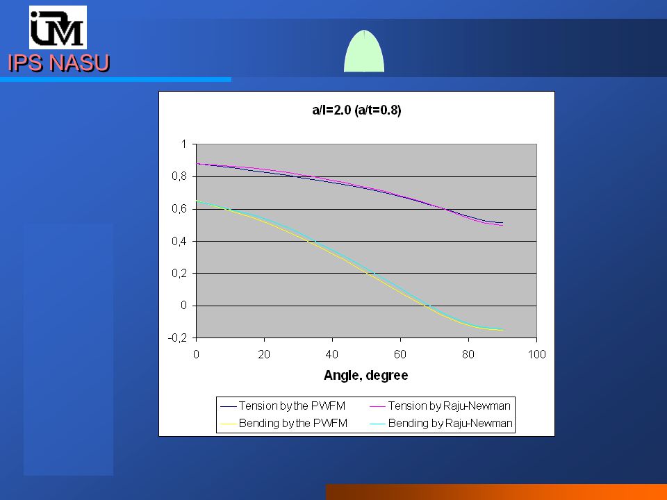
SIF along crack front (angle), homogeneous loading IPS NASU Check of the PWFM accuracy for semi-elliptic cracks Check of the PWFM accuracy for semi-elliptic cracks 0 90
, homogeneous loading IPS NASU Check of the PWFM accuracy for semi-elliptic cracks Check of the PWFM accuracy for semi-elliptic cracks 0 90")
10
IPS NASU

12
Dependence SIF from ratio a/l

13
IPS NASU Dependence SIF from ratio a/l

14
IPS NASU Weight Function Method for 3-D bodies. Simplified (speed up) approach. Weight Function Method for 3-D bodies. Simplified (speed up) approach. The problem: triple integral (square and contour) with singularity at the edge high computation cost (especially for repeating – fatigue, stress-corrosion,… – calculations) !!! The solution: approximation of the stress law with function of the next type:, calculation of the SIF array for each stress function. Approximate SIF function can be build as linear combination of precalculated.. Approximate SIF function can be build as linear combination of precalculated.
 approach. The problem: triple integral (square and contour) with singularity at the edge high computation cost (especially for repeating – fatigue, stress-corrosion,… – calculations) !!. The solution: approximation of the stress law with function of the next type:, calculation of the SIF array for each stress function. Approximate SIF function can be build as linear combination of precalculated.. Approximate SIF function can be build as linear combination of precalculated..")
15
IPS NASU Weight Function Method for 3-D bodies. Simplified (speed up) approach. Weight Function Method for 3-D bodies. Simplified (speed up) approach. Polynomial example The expression for dimensionless SIF functions :
 approach. Polynomial example The expression for dimensionless SIF functions :.")
16
IPS NASU Weight Function Method for 3-D bodies. Simplified (speed up) approach. Weight Function Method for 3-D bodies. Simplified (speed up) approach. Polynomial example For simple expressions for I ij A,C (α) were obtained : Depth of crackLoading (0, j)I 0j (0)I 0j (π/2) =a/t jExactApprox.ExactApprox. 0.201230123 1.140 0.197 0.074 0.038 1.140 0.196 0.078 0.040 1.015 0.715 0.588 0.512 1.015 0.726 0.605 0.533 0.501230123 1.219 0.221 0.085 0.044 1.219 0.214 0.085 0.044 1.050 0.729 0.596 0.515 1.050 0.742 0.610 0.540 Semi-elliptical crack on the inner surface of the cylinder.
 approach. Polynomial example For simple expressions for I ij A,C (α) were obtained : Depth of crackLoading (0, j)I 0j (0)I 0j (π/2) =a/t jExactApprox.ExactApprox Semi-elliptical crack on the inner surface of the cylinder..")
17
IPS NASU Application of the peveloped methods: Software “ReactorA” Application of the peveloped methods: Software “ReactorA” Residual life is calculated deterministically and probabilistically (MASTER CURVE approach) for various points of crack front This program is intended for calculation of reactor pressure vessel residual life and safety margin with respect to brittle fracture This program is intended for calculation of reactor pressure vessel residual life and safety margin with respect to brittle fracture. User sets loading and temperature fields in the different moments of time. Then material fracture toughness, embrittlement parameters are also set by user User sets loading and temperature fields in the different moments of time. Then material fracture toughness, embrittlement parameters are also set by user.

18
IPS NASU ReactorA advantages The sizes of stress and temperature fields' aren't bounded Number of time moments is bounded only by the memory size Cladding is taken into account Welding seam and heat-affected area are taken into account Deterioration is taken into account not only as shift of the material fracture toughness function but also as its inclination Original feature of the software is using of the author variant of the weight function method. It allows to set loading on the crack surface in the form of table. The sizes of stress and temperature fields' aren't bounded Number of time moments is bounded only by the memory size Cladding is taken into account Welding seam and heat-affected area are taken into account Deterioration is taken into account not only as shift of the material fracture toughness function but also as its inclination Original feature of the software is using of the author variant of the weight function method. It allows to set loading on the crack surface in the form of table.

19
Input Data 1) Stress field for time Table arbitrary size IPS NASU 3. Residual Life calculation of the NPP pressure vessel using fracture mechanics methods

20
IPS NASU 2) Temperature field for time Input Data Table arbitrary size
 Temperature field for time Input Data Table arbitrary size")
21
a ) Axial with weld seam IPS NASU Input Data weld seam heat-affected zone base material cladding crack weld seam heat-affected zone base material cladding crack base material cladding crack base material cladding crack b) circumferential 3) Crack types
 Axial with weld seam IPS NASU Input Data weld seam heat-affected zone base material cladding crack weld seam heat-affected zone base material cladding crack base material cladding crack base material cladding crack b) circumferential 3) Crack types")
22
IPS NASU 4) The basic material characteristics 1. Arctangents 2. Exponent Common shape of the crack growth resistance function is for user function A takes from coordinates of first point Common shape of the crack growth resistance function is for user function A takes from coordinates of first point 3. User (pointed) function
 function.")
23
IPS NASU 1. Shift 2. Inclination 5) Shift and inclination conceptions
 Shift and inclination conceptions")
24
IPS NASU a)Analytical form b)Table form 6) Dependence of shift on radiation
Analytical form b)Table form 6) Dependence of shift on radiation")
25
IPS NASU Results Scenario – Break of the Steam Generator Collector WWER-1000 operated at full power It is given : - stress field, - temperature field, = 1000, 2000, 2800, 3000, 3160, 3600, 4000 sec - time points It is given : - stress field, - temperature field, = 1000, 2000, 2800, 3000, 3160, 3600, 4000 sec - time points Axial crack. Half-length l - 40 мм., depth a - 50 мм. Axial crack. Half-length l - 40 мм., depth a - 50 мм.

26
IPS NASU a) Dependences of the calculated and critical SIF from temperature for time = 3000 sec SIF for base material --//-- for weld seam Critical SIF for base material --//-- for weld seam --//-- for heat-affected area SIF for base material --//-- for weld seam Critical SIF for base material --//-- for weld seam --//-- for heat-affected area
 Dependences of the calculated and critical SIF from temperature for time = 3000 sec SIF for base material --//-- for weld seam Critical SIF for base material --//-- for weld seam --//-- for heat-affected area SIF for base material --//-- for weld seam Critical SIF for base material --//-- for weld seam --//-- for heat-affected area")
27
IPS NASU history for basic material --//-- for weld seam critical SIF for basic material --//-- for weld seam --//-- for heat-affected area history for basic material --//-- for weld seam critical SIF for basic material --//-- for weld seam --//-- for heat-affected area b) History of the dependences calculated SIF from temperature for some points and all times intervals and critical SIF TT
 History of the dependences calculated SIF from temperature for some points and all times intervals and critical SIF TT")
28
IPS NASU fields for chosen history points minimal margin margin for time points fields for chosen history points minimal margin margin for time points c) Table of the calculated temperature margin for all points of crack front and time points c) Table of the calculated temperature margin for all points of crack front and time points
 Table of the calculated temperature margin for all points of crack front and time points c) Table of the calculated temperature margin for all points of crack front and time points")
29
calculated temperature margin shift of the temperature by user table shift of the temperature by analytical model calculated temperature margin shift of the temperature by user table shift of the temperature by analytical model IPS NASU d) Figure of the calculated margin
 Figure of the calculated margin")
30
IPS NASU New geometry for axial crack Calculated temperature margin Half length l - 60мм Depth a - 40 мм Half length l - 60мм Depth a - 40 мм Results for other crack geometries

31
New geometry for axial crack Half length l - 40мм Depth a - 60 мм Half length l - 40мм Depth a - 60 мм IPS NASU Calculated temperature margin

32
Half length l - 60мм Depth a - 30 мм Half length l - 60мм Depth a - 30 мм New geometry for circumferential crack IPS NASU calculated temperature margin

33
IPS NASU 1. Failure probability calculation for structural element 2. Failure probability calculation for crack 3. Calculation parameters 4. In addition К min, K 0 (Т), В 0, b - arbitrarily P f = 63,2% К min = 20 В 0 = 25 мм b = 4 Implementation MASTER CURVE Conception Implementation MASTER CURVE Conception
, В 0, b - arbitrarily P f = 63,2% К min = 20 В 0 = 25 мм b = 4 Implementation MASTER CURVE Conception Implementation MASTER CURVE Conception.")
34
For time T =0 failure probability equal 1.07*10 -05 IPS NASU Time point t 4 = 3000 sec Axial crack half length l - 40 мм., depth a - 50 мм. Time point t 4 = 3000 sec Axial crack half length l - 40 мм., depth a - 50 мм. SIF dependences on angle Result for main scenario

35
Dependences of logarithm probability on T IPS NASU

36
Probability density for T = 50

37
IPS NASU Application of the developed methods: Software “WFM” Application of the developed methods: Software “WFM” SIF, grow of the crack dimensions in time and endurance are calculated. “Until specified depth” or “until specified count of cycles” modes are presented. This program is intended for SIF calculation for different (1-D and 2-D) types of cracks and for endurance estimation with using different fatigue and stress- corrosion laws. User sets “maximum”, “minimum” and “corrosion” loading fields.
 types of cracks and for endurance estimation with using different fatigue and stress- corrosion laws. User sets maximum , minimum and corrosion loading fields..")
38
1. Damages 2. Cracks IPS NASU WFM: implemented types of damages and cracks

39
IPS NASU WFM: example of result window. Input and output data can be exchanged with clipboard.

40
IPS NASU CONCLUSION 1. Efficient methods of stress intensity factor (SIF) calculation are developed. 2. The computer software which reflected all modern requirements for brittle strength analysis of Reactor Pressure Vessel is created. 1. Efficient methods of stress intensity factor (SIF) calculation are developed. 2. The computer software which reflected all modern requirements for brittle strength analysis of Reactor Pressure Vessel is created.
 calculation are developed. 2. The computer software which reflected all modern requirements for brittle strength analysis of Reactor Pressure Vessel is created. 1. Efficient methods of stress intensity factor (SIF) calculation are developed. 2. The computer software which reflected all modern requirements for brittle strength analysis of Reactor Pressure Vessel is created..")
Similar presentations


 of representative samples or strength parameters or slope.>")


 usually define the onset of “damage” initiation in the material Once critical stress.>")


