Download presentation
Presentation is loading. Please wait.

1
Wind Turbine Testing

2
Why Test? Limited number of machines suitable for polar applications Identify the good and bad machines Identify the good and bad manufacturers Gain familiarity with the systems Decrease failure rates to promote greater project success

3
PFS-South Test Site 8,200’ elevation in southern Colorado – Air density 20% less than sea level Subject to very high wind speeds Also (we know now) extreme turbulence Fairly cold temps – but not polar cold Accessibility: Ability to monitor in person and remotely No difficult code or zoning issues No permit required
 extreme turbulence Fairly cold temps – but not polar cold Accessibility: Ability to monitor in person and remotely No difficult code or zoning issues No permit required")
4
The Testing Setup 50’ guyed, tilt-up type tower from SWWP provides economical system, easy to access turbine (about 15 - 20 minutes to lower) Robust foundation and grounding system 2.5” schedule 40 pipe can handle up to 1kW machines WLAN/broadband satellite communications APRS World supplied monitoring system Back-up solar (PV) system to keep batteries charged
 Robust foundation and grounding system 2.5 schedule 40 pipe can handle up to 1kW machines WLAN/broadband satellite communications APRS World supplied monitoring system Back-up solar (PV) system to keep batteries charged")
5
Earth Grounding Detail

6
Foundation Detail

7
Raise/Lower System

8
Initial Tower Raising

9
What Machine to Test? APRS World - WT10/14 - Nicely balanced design - Light yet powerful - 3-Phase AC output from turbine - Black finish - Designed for fast field installation - Reconfigurable for different wind regimes - Initial discussions suggested an interested and engaged manufacturer

10
WT14 Wind Turbine 3 blades, horizontal axis, upwind Rotor – 1.4 m (4.7 ft) rotor diameter – Glass filled nylon blades Generator – Permanent magnet – 3 ∅ – Variable voltage and frequency – 1kW nominal capacity 11 kg (24 lbs) weight
 rotor diameter – Glass filled nylon blades Generator – Permanent magnet – 3 ∅ – Variable voltage and frequency – 1kW nominal capacity 11 kg (24 lbs) weight")
11
WT14 Manufacturer Ratings Battery charging 24 or 48 volt battery – 4.5 m/s (10 MPH): cut in speed – 5.4 m/s (12 MPH): 50 watts! – 13.5 m/s (30 MPH): 300 watts – 55 m/s (123 MPH): survival speed “Optimized for power production in moderate wind regimes. Survives occasional intense high wind.”
: 300 watts – 55 m/s (123 MPH): survival speed Optimized for power production in moderate wind regimes. Survives occasional intense high wind. .")
12
WT10 Wind Turbine 3 blades, horizontal axis, upwind Rotor – 1.0 m (3.3 ft) rotor diameter – Glass filled nylon blades Generator – Permanent magnet – 3 ∅ – Variable voltage and frequency – 1kW nominal capacity 10 kg (23 lbs) weight
 rotor diameter – Glass filled nylon blades Generator – Permanent magnet – 3 ∅ – Variable voltage and frequency – 1kW nominal capacity 10 kg (23 lbs) weight")
13
WT10 Manufacturer Ratings Battery charging 24 or 48 volt battery – 4.5 m/s (10 MPH): cut in speed – 13.5 m/s (30 MPH): ~300 watts – 31.5 m/s (70 MPH): ~750 watts – >70 m/s (>157 MPH): survival speed “Optimized for high wind energy sites.”
: cut in speed – 13.5 m/s (30 MPH): ~300 watts – 31.5 m/s (70 MPH): ~750 watts – >70 m/s (>157 MPH): survival speed Optimized for high wind energy sites.")
14
WTAPRS Polar Relevant Features Light weight and compact Installation – Tool less assembly while wearing gloves Connectorized electrical (standard) Quick attach tail (standard) Quick attach blades (option) Quick attach to mast (option) – Very quick installation – Materials selected for resilience at low temperatures – Easy to rig Carabineer hole for lifting Can be attached to harness and carried up tower
 Quick attach tail (standard) Quick attach blades (option) Quick attach to mast (option) – Very quick installation – Materials selected for resilience at low temperatures – Easy to rig Carabineer hole for lifting Can be attached to harness and carried up tower")
15
WTAPRS Polar Relevant Features (continued) Operation – Entirely sealed O-rings for chassis components Sealed bearings – Black to promote ice melt – Anodized aluminum and stainless steel hardware – No electronics in turbine
 Operation – Entirely sealed O-rings for chassis components Sealed bearings – Black to promote ice melt – Anodized aluminum and stainless steel hardware – No electronics in turbine")
16
Test Setup Independent autonomous system Charges 24 volt battery Excess power is dumped to dump load Turbine and meteorological data – Logged to SD card – Sent via 802.11b / Hughes to WorldData – Sent via APRS World / SPOT Modem to WorldData

17
Test Setup – Meteorological Sensors Meteorological Sensors Anemometer and wind vane – At ~45ft up tower on sensor boom Temperature – At ~6ft on tower in solar radiation shield – Enclosure temperature IP Camera – Turbine and top half of tower Turbine Sensors Battery voltage Turbine current Turbine RPM – Sensed from turbine wild AC Dump load – Duty cycle (% of available load) – kWh dumped – Battery temperature
 – kWh dumped – Battery temperature")
18
Live (Internet) Data Website Note: This screenshot isn’t from Tracy’s PFS site due to internet bandwidth limitations. This is a test unit in Minnesota. Live data at: http://data.aprsworld.com/sites/wtaprs/fremont/

19
Telemetry - Satellite APRS World / SPOT Satellite Telemetry – Globalstar network – Low cost SPOT network – <$400 hardware & <$100 year data – 6 hour highly compressed message with Wind speed / gust / average Turbine RPM / average RPM / current Temperature Dump Load kWh, duty cycle, battery temperature Battery Voltage

20
Satellite Telemetry Data Website Example of historical data: Example of “live” data:

21
WT14 @ PFS-South Installed 2012-11-25 Instrumentation not completely commissioned Produced energy, lots of it – ~45 kWh total production to 2013-01-11 Wind events – Anemometer not connected – RPM data implies multiple storms

22
WT14 Failure 1 @ PFS-South on January 11, 2013 Problems – Internal permanent magnet generator failure Rotor became detached from main shaft – Hub / main bearing interference Rotating part wore and came in contact with non- moving nose of turbine – Yaw Turbine would yaw 360° in high winds Video of turbine yaw in high winds: http://youtu.be/LIp3uZJ5oC8http://youtu.be/LIp3uZJ5oC8

23
WT14 Failure 1 Causes: Permanent Magnet Generator Failure Known weakness in design of rotor to shaft interface – Manufacturer is beginning to manufacture improved design with multiple rotor to shaft retention features Manufacturer attributes to wind event exceeding ratings of turbine and exasperating known design weakness

24
Failed Rotor / Shaft

25
PMG Rotor Shaft Detail Revised design (what won’t fail) Original Design (what failed)
 Original Design (what failed)")
26
WT14 Failure 1 Causes: Hub / Main Bearing Interference Defect in design – Previous generations had much larger gap between rotating hub and fixed body – Smaller gap adopted to minimize area for ice accumulation – Wear in component allowed surfaces to rub Manufacturer attributes to design defect and premature failure caused by excessive turbulence in high winds.

27
Hub / Main Bearing Photo

28
WT14 Failure 1 Causes: Excessive yaw Intrinsic to design of high speed wind turbine – Similar behavior documented in many other small high speed wind turbines Larger tail was installed – Appeared to stabilize the machine – up to a point Manufacture argues that excessive yaw is due to site turbulence - WT10 has not exhibited yaw instability Air-X wind turbine exhibiting the same yaw behavior: http://youtu.be/5ilfsqQAULEhttp://youtu.be/5ilfsqQAULE

29
WT14 Failure 2 @ PFS-South on 2013-03-04 Turbine failure in high wind 40 m/s (90 MPH) event – Loss of blades All three blades broke at root Root of blades remained bolted to hub – Bent tail ~15 degree bend in PROTOTYPE larger tail
 event – Loss of blades All three blades broke at root Root of blades remained bolted to hub – Bent tail ~15 degree bend in PROTOTYPE larger tail")
30
WT14 Failure 2 Causes: Loss of Blades Hypothesis: Blade injection molding process / mold design causes weak spot at location where blades failed High wind events / rotor over-speed stress the blades and caused failure Manufacturer is modifying injection molding tooling to eliminate week spot around hold in blade Manufacturer attributes failure to turbine exceeding survival speed and design defect in blade tool. Induced blade failure test by manufacturer: https://www.youtube.com/watch?v=riGjq9Arlechttps://www.youtube.com/watch?v=riGjq9Arlec

31
WT14 Failure 2 Causes: Bent Tail Damage to turbine housing where tail installs indicates large motion in tail. Likely caused by unbalanced momentary operation of the turbine with 1 or 2 blades. Note: This was a prototype tail that is larger than production WT14 tail. Increased size has larger moment and may exceed yield strength of material.

32
WT14 Failed Blade and Tail

33
Tracy’s WT14 Observations Excellent low speed (12 mph)to mid speed (40 mph) wind performance Loud and scary in high wind (>50 mph) > 100dBA @ 70+ mph wind speeds Not currently suitable for use in high wind areas – Design improvements may help Not good for turbulent wind!
to mid speed (40 mph) wind performance Loud and scary in high wind (>50 mph) > 70+ mph wind speeds Not currently suitable for use in high wind areas – Design improvements may help Not good for turbulent wind!")
34
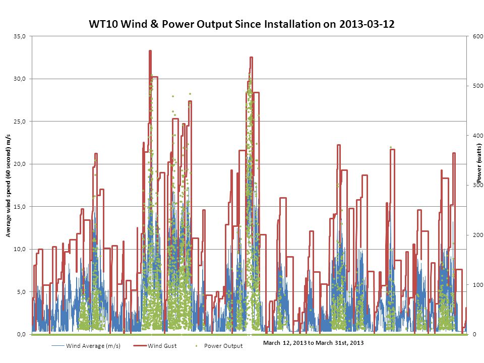
WT10 @ PFS South Installed 2013-03-12

36
WT10 Observations Quiet operation Higher starting speed Stable operation

37
Conclusions Testing has been mutually beneficial WT10 is a solid performer for high speed/turbulent wind regimes, but may not be optimal for lower wind speed areas like North Slope WT14 performs very well at low to moderate speeds, but cannot (currently) withstand prolonged high/turbulent winds
 withstand prolonged high/turbulent winds")
38
Conclusions Continued The basic APRS World design is solid, continually improving and suitable for polar applications. The ability to reconfigure for different wind regimes seems like a very desirable feature. Very cold weather performance not yet qualified, but should be good. Possibility for polar extreme model (e.g., ceramic bearings)?? Great to work with a willing and engaged manufacturer. – APRS World is looking for looking for polar testing oprotunities
 . Great to work with a willing and engaged manufacturer. – APRS World is looking for looking for polar testing oprotunities.")
39
Questions and Comments? Tracy Dahl – Polar Field Services, Inc. – Tracy@Polarfield.com Tracy@Polarfield.com – 303.518.8713 James Jarvis – APRS World, LLC – jj@aprsworld.com jj@aprsworld.com – 507.454.2727 Information on the WT10 and WT14 at: http://www.aprsworld.com/wtaprs/

Similar presentations


 Blue font and lines – need to know.>")


 Heather Blaha Matt Fuxa Joey King Michael McConnell Domenic Tassoni.>")


