Download presentation
Presentation is loading. Please wait.

1
BENJAMIIN C. KUO, FELLOW, IEEE, AND GURDIAL SINGH, MEMBER, IEEE IEEE TRANSACTIONS ON INDUSTRY APPLICATIONS, VOL. IA.-l, NO. 4, JULY/AUGUST 1975 Professor: 王明賢 Class: 控晶四甲 Student: 蔡景棠

2
I. INTRODUCTION THE DC-TYPE hybrid step motor described in this paper consists of a variable-reluctance (VR) step motor with a rotor that is wound similar to a dc motor [1]. The development of such a device is nmotivated by the limited torque capability at higher speeds of existing step motors. Although the current generation step motors can generally provide adequate detent torque, the output is severely limited at higher operating speeds. This limitation is apparently an inherent problem, since the highly reactive stator windings have to be sequentially switched to step the mot-or. As the speed increases, the currents in the windings simply do not have enough time to build up and decay sufficiently, thereby reducing the torque capability of the motor. The use of higher voltages writh series voltage- dropping resistors or dual voltage schemes alleviates the problem to some extent, but the improvement is limited by practical voltage values and loNwer operating efficiencies.
 step motor with a rotor that is wound similar to a dc motor [1]. The development of such a device is nmotivated by the limited torque capability at higher speeds of existing step motors. Although the current generation step motors can generally provide adequate detent torque, the output is severely limited at higher operating speeds. This limitation is apparently an inherent problem, since the highly reactive stator windings have to be sequentially switched to step the mot-or. As the speed increases, the currents in the windings simply do not have enough time to build up and decay sufficiently, thereby reducing the torque capability of the motor. The use of higher voltages writh series voltage- dropping resistors or dual voltage schemes alleviates the problem to some extent, but the improvement is limited by practical voltage values and loNwer operating efficiencies..")
3
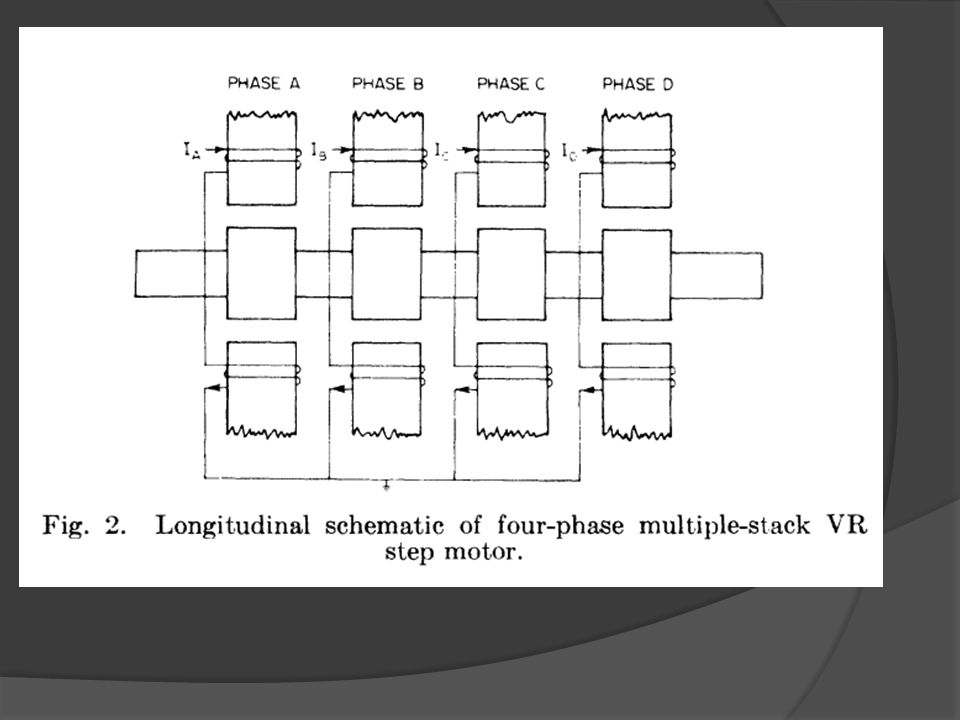
II. OPERATING PRINCIPLE OF DC-TYPE HYBRID STEP MOTOR In order to describe the operation of this type of hybrid motor, consider a four-phase multiple-stack VR step motor. The end view of one phase of the mnotor is shown in Fig. 1,and a longitudinal schemnatic of all four phases is shown in Fig. 2. With 20 teeth, t,his particular motor has 80 steps per revolution, or 4.5° per step.

6
III. DESIGN CONSIDERATIONS A. Design of Hybrid Motor by Modifying Existing Step Motor We shall first consider an existing step motor whose Configuration will be utilized in the design of a hybrid motor. Because the step motor portion has already been designed, the parts that remain to be designed include the rotor winding and the commiutator. With a fixed number of poles and a given number of rotor teeth, a double-layer lap winding (progressive or retrogressive) is generally the only available option. The rotor slots may have to be modified slightly to better accommodate the winding coils,although care has to be taken so as not to change the stepping characteristics (especially, detent torque) too drastically.
 is generally the only available option. The rotor slots may have to be modified slightly to better accommodate the winding coils,although care has to be taken so as not to change the stepping characteristics (especially, detent torque) too drastically..")
7
B. Complete Design of Hybrid M1otor with No Constraints on Configuration This procedure, which consists of several steps, is now briefly outlined. (1) Input Speczfications: These have to be fed to the program first and include data for dc operation such as rated power output, rotor voltage, rated torque or speed, and the number of stator poles. In addition, because the motor has to be able to step, information regarding the number of rotor and stator teeth, the number of phases (stacks), and the nominal air-gap length have to be provided at this time. In order to insure adequate stepping torque, the minimum rotor diameter may also be specified if the number of teeth is large. (2) Design of Rotor Teeth and Rotor Winding: This is the first stage of the design. Fixed slot width and tooth width ratios are utilized to obtain initial slot and tooth dimensions. Conductor sizes are automatically selected from a prestored copper wire table, and the rotor winding is designed. (3) Initial Magnetic Circuit Analysis and Field Winding Design: Various air-gap flux densities are selected and a magnetic circuit analysis is performed to determine the MMF required for the stator and rotor teeth and the air gap. The \I\IF in the remaining portions of the circuit is estimated and a variety of field structures are designed for each air-gap flux density chosen previously.
 Input Speczfications: These have to be fed to the program first and include data for dc operation such as rated power output, rotor voltage, rated torque or speed, and the number of stator poles. In addition, because the motor has to be able to step, information regarding the number of rotor and stator teeth, the number of phases (stacks), and the nominal air-gap length have to be provided at this time. In order to insure adequate stepping torque, the minimum rotor diameter may also be specified if the number of teeth is large. (2) Design of Rotor Teeth and Rotor Winding: This is the first stage of the design. Fixed slot width and tooth width ratios are utilized to obtain initial slot and tooth dimensions. Conductor sizes are automatically selected from a prestored copper wire table, and the rotor winding is designed. (3) Initial Magnetic Circuit Analysis and Field Winding Design: Various air-gap flux densities are selected and a magnetic circuit analysis is performed to determine the MMF required for the stator and rotor teeth and the air gap. The \I\IF in the remaining portions of the circuit is estimated and a variety of field structures are designed for each air-gap flux density chosen previously..")
8
(4) Solution and Final Calculations: From the various designs obtained in step 3), the most promising one (or more) is selected. The magnetic circuit calculations, includinig leakage flux calculation, are performed in detail and the densities in each section are checked out. Final values for output torque, no-load/full-load speed, power output, and efficiency are obtained and compared with the original specifications. Any major discrepancies or undesirable parameters are spotted and, if necessary, steps 2) and/or 3) are repeated with modified specifications. (5) Stepping Torque at-d Other Parameters: In this step the static detent torque is estimated and the calculations for rotor inertia and the various temperature rises are performed. Again, if there is any undesirable parameter, the appropriate data changes are made and the preceding steps are repeated. Since all calculations are performed on a digital computer, the total computation time needed to repeat steps 2) through 5) is generally just a few minutes.
 and/or 3) are repeated with modified specifications. (5) Stepping Torque at-d Other Parameters: In this step the static detent torque is estimated and the calculations for rotor inertia and the various temperature rises are performed. Again, if there is any undesirable parameter, the appropriate data changes are made and the preceding steps are repeated. Since all calculations are performed on a digital computer, the total computation time needed to repeat steps 2) through 5) is generally just a few minutes..")
9
IV. DESCRIPTION OF PROTOTYPES Prototype I This hybrid motor was designed by modifying an existing step motor. The step motor that was used has the following characteristic data: type multiple-stack VR number of phases4 number of rotor teeth20 step size 4.50 (80 steps per revolution) current rating 6 A per phase static torque 750 oz-in per phase at rated current motor outer diameter 4.56 in motor length 12.0 in poles per stack 4.
 current rating 6 A per phase static torque 750 oz-in per phase at rated current motor outer diameter 4.56 in motor length 12.0 in poles per stack 4..")
11
This step motor is modified to yield a hybrid motor using the design procedure of Section III-A. The following additional characteristic data are obtained: rotor windingdouble layer, simple lap wire size and materialno. 25 AWG, copper Insulationclass type A (heavy formvar) number of conductors36 per slot commutator and20 segment, copper, 4 brushes brushes900 apart rated winding current 2.5 A per conductor, 4 parallel circuits, - 10 A rated rotor current rated de torque 330 oz-in.
 number of conductors36 per slot commutator and20 segment, copper, 4 brushes brushes900 apart rated winding current 2.5 A per conductor, 4 parallel circuits, - 10 A rated rotor current rated de torque 330 oz-in..")
13
B. Prototype II This hybrid motor was completely designed from the first principles and includes both the dc and stepping aspects of the device. The input specifications were torque output500 oz-in at 4500 r/min steps per revolution96 (3.75°/step) number of phases4. Although no static torque was directly specified, the figure of 700 oz-in was considered desirable.
 number of phases4. Although no static torque was directly specified, the figure of 700 oz-in was considered desirable..")
14
The computerized design procedure of Section III-B was applied to the design of this motor. After several iterations the following data were accepted:

16
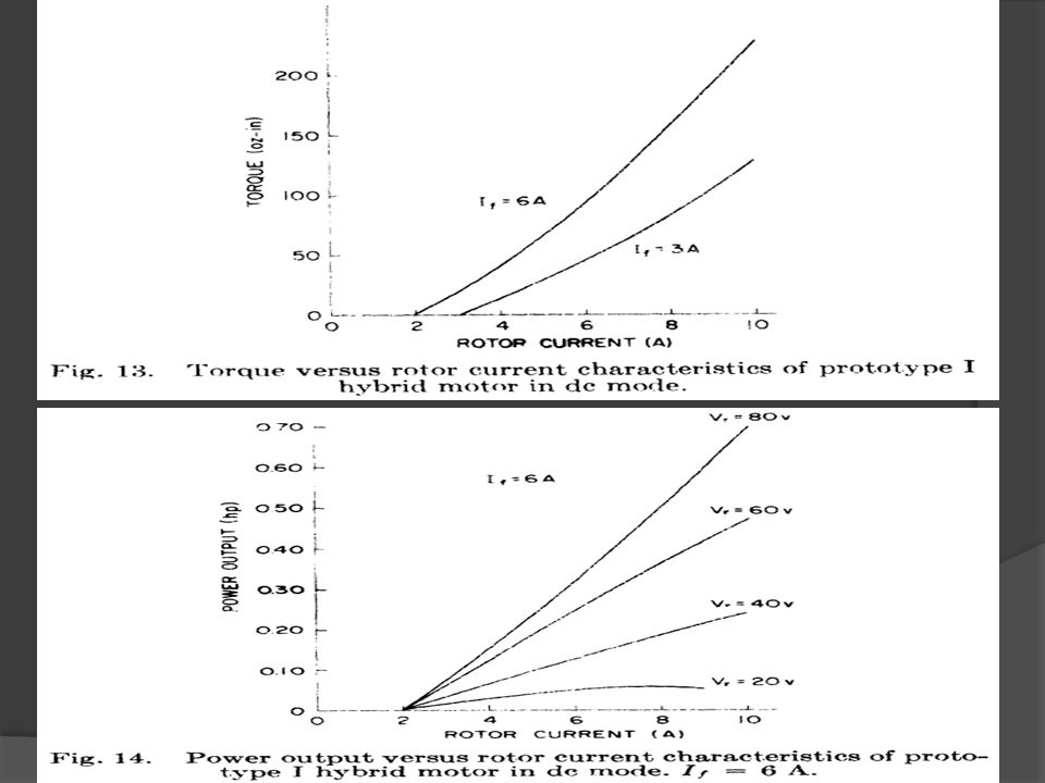
V. OPERATING MODES AND TEST RESULTS A. Stepping Mode This mode corresponds to normal stepping operation with the rotor left unenergized. The motor is operating as a regular step motor and any suitable drive scheme may be utilized. In addition, the motor can be run in either the open-loop mode or the closed-loop mode. B. DC-Aided Stepping Mode In this case the stator windings of the motor are stepped normally in an open-loop scheme and the rotor is also energized from a dc source. The pulsating flux, -which is established when the stator phases are being stepped, will interact with the rotor current and produce a pulsating torque in each rotor section. The total torque from all sections, however, N-ill be relatively uniform, and with the appropriate polarity for rotor current, this torque can be made to aid the stepping torque. Thus, although the motor is still running open loop, its load capability is enhanced by adding the de torque to it. C. DC Mode In this mode of operation, the hybrid motor is run as a separately-excited dc motor. The stator windings are all energized with equal currents (If) and the rotor is connected to another dc supply. The speed of operation is decided, as in a dc motor, by the stator flux, the rotor voltage, and the load torque.
 and the rotor is connected to another dc supply. The speed of operation is decided, as in a dc motor, by the stator flux, the rotor voltage, and the load torque..")
20
VI. POINT-TO-POINT CLOSED-LOOP CONTROL In this section the application of the hybrid motor for point-to-point closed- loop control is described. The control versatility of the hybrid motor makes it a particularly effective actuator for point-to-point or fixed-distance applications. A closed-loop controller for fixed-distance control with the prototype II hybrid motor has been designed and constructed. The block diagram of this controller is shown in Fig. 18. A typical velocity profile generated by driving the hybrid motor with this controller is shown in Fig. 19. Acceleration is provided by running the hybrid motor

22
VII. CONCLUSION A new hybrid step motor has been described.The feasibility of an active rotor configuration obtained by winding the rotor of a VR step motor is demonstrated by two prototypes. Improved open-loop slewing performance in the dc-aided stepping mode and substantial running torque at higher speeds in the dc mode are characteristic of this type of motor. The multimode operation of this motor also makes it effective as a closed-loop point-to- point actuator. Although more work is needed in developing this device, the results presented here conclusively indicate its Feasibility and effectiveness for large power applications.

23
REFERENCES [1l "Electric motor adapted for both stepping and continuous operation," U. S. patent 3 809 990. [2] P. N. Budzilovich, "Use of electrohydraulic stepping motors for all-digital drives," Contr. Eng., vol. 17, pp. 82-88, Jan. 1970. [3] E. P. Bucher and T. T. Smith, "Stepping motor applications for machine tool drives," Electromech. Design, vol. 16, pp. 18-21, Sept. 1972. [4] M. I. S. Bajwa, "Open-loop control by using electrohydraulic motors," in Proceedings: Second Annual Symposium on Incremental Motion Control Systems and Devices, B. C. Kuo, ed. Urbana, Ill.: Dep. Elec. Eng., Univ. Illinois at Urbana-Champaign, pp. T1-T18, 1973. [5] J. Jacquin, "An all-electric high-power step motor," in Proceedings: Second Annual Symposium on Incremental Motion Control Systems and Derices, B. C. Kuo, ed. Urbana, Ill.: Dep. Elec. Eng., Univ. Illinois at Urbana-Champaign, pp. N1-N5, 1973. [6] A. F. Puchstein, The Design of Small Direct Current Motors. New York: Wiley, 1961. [7] A. E. Clayton and N. N. Hancock, The Performance and Design of Direct Current Machines. London: Pitman, 1969. [8] M. G. Say, Electrical Engineering Design Manual. London: Chapman and Hall, 1962.

Similar presentations