Download presentation
Presentation is loading. Please wait.

1
Modeling Suspended Growth Systems – see Grady, Daigger & Lim Environmental Biotechnology CE421/521 Tim Ellis (originally prepared by Dr. Eric Evans) October 25, 2007
 October 25,")
2
Reactor performance as a function of SRT. Fails to account for: Particulate removal rate Anaerobic/anoxic conditions Variable flow and loading Biological nutrient removal Monod Equation and Unified Model

3
International Association on Water Quality Activated Sludge Model 1 (IAWQ-ASM 1) In 1983, IAWQ appointed a task group to develop a model. In 1986, ASM 1 was completed. ASM 1 able to predict performance of soluble and particulate substrate removal, nitrification and denitrification under steady state and dynamic conditions.

4
Traditional vs. Lysis-regrowth

6
ASM 1 Tracks 13 individual components through eight separate processes. Assumes heterotrophic growth under anoxic conditions. Limited anaerobic activity. Uses lysis-regrowth approach

8
IAWQ – ASM 2 In 1995, ASM 2 was released capable of tracking biological phosphorus flows. Now able to model enhanced biological phosphorus removal.

9
ASM 2 Tracks 19 separate components through 19 processes. 22 stoichiometric coefficients and 42 kinetic parameters Ammonification and hydrolysis simplified to stoichiometric terms; i.e. rates implicit. Includes anaerobic fermentation, uptake of acetate, formation of PHB and PHAs, and release of soluble phosphate from hydrolysis of polyphosphate. Several assumptions made that constantly need revision as knowledge evolves.

10
Activated Sludge Models Cannot solve analytically. Use computer algorithm based on numerical techniques SSSP, Bidstrup and Grady (MS-DOS based, ASM 1) GPS-X, Hydromantis, Inc. BioWin, EnvironSim Associates Limited. ASIM & AQUASIM, Swiss Federal Institute of Aquatic Science and Technology, EAWAG. EFOR, DHI, Inc. STOAT, WRc Group. WEST, Hemmis N. V. SIMBA, IFAK-System GmbH. ASM 2 integrated into software algorithm provides a powerful tool.
 GPS-X, Hydromantis, Inc. BioWin, EnvironSim Associates Limited. ASIM & AQUASIM, Swiss Federal Institute of Aquatic Science and Technology, EAWAG. EFOR, DHI, Inc. STOAT, WRc Group. WEST, Hemmis N. V. SIMBA, IFAK-System GmbH. ASM 2 integrated into software algorithm provides a powerful tool..")
11
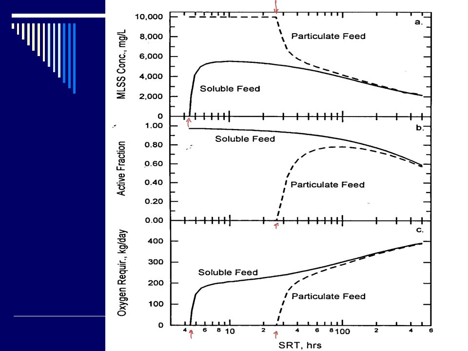
Steady-state performance – Particulate versus Soluble Particulate hydrolysis is a rate limiting step. A particulate feed requires a longer SRT to achieve treatment. Particulates compose all of MLSS at low HRTs and active fraction is washed out.

13
Dynamic performance – Particulate and Soluble Flow & substrate concentrations vary during diurnal pattern. Particulate and soluble feeds have different effects on performance.

15
Nitrification – low max and K S

16
Diurnal flow has a negative effect on nitrification

17
Nitrification Nitrifiers are affected by: Temperature Low oxygen concentrations Inhibition by some organics

18
Nitrification Autotrophs are a small fraction of MLSS. Nitrification consumes large amount of oxygen.

19
Denitrification Denitrification – Organics are electron donor Nitrates are electron acceptor Optimum Carbon to Nitrate ratio based on balance between electron donor and acceptor. Nitrate Carbon

20
Denitrification Oxygen is preferred electron acceptor…

21
Diurnal flow with different aeration strategies Single CSTR may be set to: Maintain a constant dissolved oxygen concentration in the tank Constant oxygen flow into tank

23
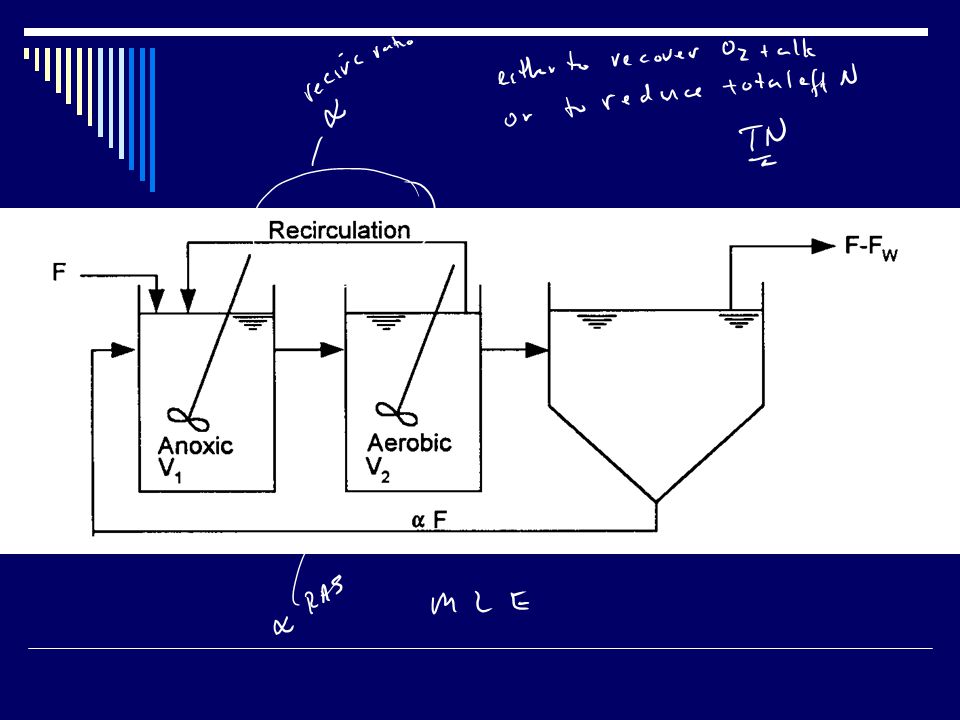
Modified Ludzack Ettinger Use an anoxic basin and an aerobic basin to select for denitrification after nitrification… Why denitrify? Where would you place anoxic selector in flow scheme?

25
Effect of SRT on MLE SRT is biomass in system divided by biomass wasted from system where system includes both aerobic and anoxic basins…

26
CSTR MLE Dashed lines indicate performance of a single CSTR of the same volume as the anoxic and aerobic reactors.

27
MLE Recycle affects performance in MLE Greater recycle leads to: Nitrate flow into anoxic reactor and thus higher consumption of nitrates and organics. Dilution of ammonia in anoxic reactor.

28
ANOXIC AEROBIC Solid lines indicate the anoxic (first) reactor and the dashed indicate The second (aerobic) reactor.
 reactor and the dashed indicate The second (aerobic) reactor.")
29
Diurnal Flow Wastewater flow and strength reflect activity of population. Expect diurnal flow pattern.

30
Diurnal Flow Dynamic flow results in lower performance. Performance not solely a function of SRT. Also depends on biomass change as a result of changing input. Steady-state equation Dynamic equation

31
Diurnal Flow Recall effect of diurnal flow on flow weighted nitrification in CSTR. Must increase SRT to compensate for dynamic condition.

32
Active Populations Heterotrophs Environment=Aerobic Electron Donor Organics Electron Acceptor Oxygen Benefits Removes organics that suffocate or are toxic to the environment Drawbacks Consumes Oxygen (Costs money) Produces large amounts of sludge
 Produces large amounts of sludge")
33
Active Populations Heterotrophs Environment=Anoxic Electron Donor Organics Electron Acceptor Nitrates Benefits Removes nitrates Reduces oxygen use Generates alkalinity Drawbacks Anoxic environment may be difficult to create

34
Active Populations Autotrophs Environment =Aerobic Electron Donor Ammonia Electron Acceptor Oxygen Benefits Removes ammonia Drawbacks High oxygen consumption Reduces alkalinity

35
Active Populations Phosphate Accumulating Organisms Environment=Anaerobic/Aerobic Benefits Removes Phosphorus Drawbacks Complex life cycle Requires numerous recycle lines Phosphorus rich sludge

36
EBPR

37
Virginia Initiative Plant System to remove: Organics Nitrogen Ammonia Nitrates Phosphorus Environments needed: Aerobic Anoxic Anaerobic System configuration?

38
Virginia Initiative Plant System configuration: Anaerobic Anoxic Aerobic Recirculation RAS to Anoxic MLR from Aerobic to RAS MLR from Anoxic to Anaerobic

39
VIP

40
Benefits? Drawbacks?

41
VIP

42
Important consideration: BOD 5 /Total P ratio

43
Virginia Initiative Plant BOD 5 /ΔP ratio needed for VIP Process? 15-20 mg BOD 5 /mg P

Similar presentations


>")

 Cady R. Engler, P.E. Bio & Ag Engineering Dept. Texas A&M University.>")