Download presentation
Presentation is loading. Please wait.

1
Appropriate Effluent Treatment System for Dyes and Dye-intermediates Industries
PROF. ARUNABHA MAJUMDER Emeritus Fellow School of Water Resources Engineering Jadavpur University and Ex-Director-Professor All India Institute of Hygiene and Public Health, Kolkata

2
Background Dyes and dye- intermediates Industries: Designated as ‘ Special Red’ Category Industry As per Industrial siting (Locational) Policy for West Bengal, Special red Category Industries cannot be permitted to be operated in municipal areas falling under Kolkata Metropolitan Area (KMA). Dyes and Dye-intermediates Industries are restricted / prohibited within the belt of 10 km radius around the periphery of the Leather Complex at Bantala.
 Policy for West Bengal, Special red Category Industries cannot be permitted to be operated in municipal areas falling under Kolkata Metropolitan Area (KMA). Dyes and Dye-intermediates Industries are restricted / prohibited within the belt of 10 km radius around the periphery of the Leather Complex at Bantala.")
3
Fabric dyeing is carried out by either in continuous or batch process.
In the continuous dyeing process, the dye is transferred to the fabric by passing the fabric across roller which are partially submerged in the dye solution. A batch dyeing of fabric is often accomplished in atmosphere or pressure backs or in jet dyeing machines. The majority of knitted fabric are batch dyed, using a variety of processes.

4
Salient features of the dyeing process with different classes of dyes
Direct dyes Basic dyes Vat dyes Sulphur dyes Developed dyes Napthol dyes Metal Complex dyes

5
Dyeing Processes Direct dyes: These dyes are neutral and are used for dyeing of cotton textiles on account of its natural affinity to this class of dyes, which are easy to apply without any mordants. The colors produced are stable and are fast to light. Basic dyes: These are salts of colored base and require an acid mordant such as tannic acid, tartaric and acetic acids. These dyes impart very bright colors to the fabrics. Soluble oil and soda ash are also used in the final stages of dyeing with basic dyes. A number of waste streams and other process chemicals are generated during the process.

6
Contd. Vat dyes: This group of dyes are fast dyes and are not water soluble, but are rendered soluble by strong reducing agents like sodium hydrosulphite. In this process the cloth is immersed in a vat containing the dye, dilute acid and sodium hydrosulphite and then exposed to oxidation in presence of an oxidizing agent. This is followed by scouring with a dilute alkaline solution to neutralize the excess acid. Sulfur dyes: These contain sulfur compounds and are applied together with a suitable reducing agent like sodium sulfide followed by oxidation. Developed dyes: These are colors which are produced on the fiber. At first the color is directly applied on the fabric and is converted into an unstable azodye by the addition of sodium nitrite and HCl. Next the stable form of the color is developed on the fiber by the action of beta napthol.

7
Contd. Napthol dyes: In this process the color is developed by a reversal of the sequence of operations of the dyeing with developed colours, the cloth is at first treated with beta-napthol and then diazotised with sodium nitrite and HCl. A hot soap and soda bath is used. Metal complex dyes: In the case of certain types of cotton fabrics and synthetic textiles like nylon and polyester, dyeing process is carried out by depositing inside the fibre complex salts of iron and chromium. Depending on the quantity of the metal salts and various shades khaki colour can be produced. Metallic salts are also used as catalysts for the application of wash and wear permanent press and water repellant and flame retardant finishes.

8
General Characteristics of dye house waste water
pH to 10.5 TDS – 3180 mg/l Suspended Solids (SS) 380 – 950 mg/l BOD – 820 mg/l COD – 2000 mg/l
 380 – 950 mg/l. BOD 320 – 820 mg/l. COD 750 – 2000 mg/l.")
9
Effluent Treatment process
Coagulant /Lime/flocculant 4 5 1 2 3 11 10 9 Screen Equilisation Tank Flush Mixer Primary Clarifier Bio-reactor/AT Secondary Clarifier Sump Active Carbon Filter Sludge dewatering Sludge thickener SDB 8 6 7 Final Effluent Filter Recycle/Reuse

10
Primary Treatment By the process of coagulation- flocculation and sedimentation, color, colloidal, suspended and settleable solids are removed Flush mixing for 60 to 90 sec Slow mixing for 20 to 25 minutes Detention time in PC : 150 min BOD and COD reduction: 45 to 65 %

11
Secondary Treatment Bio-reactor with Conventional or Extended aeration
Detention time: Conventional : 6 hrs to 10 hrs Extended Aeration : 12 hrs to 24 hrs(18 to 36 hrs) Aeration System: Combined system of diffused and surface aeration. Additional oxygenation capacity of the aerators in the tune of 30% to 40% need to be considered. D.O of 1.0 to 1.5 mg/l is to be maintained in the Reactor. Return Sludge Pump: at least 3 (three) pumps are necessary for maintaining optimum MLSS in the reactor Regular Sludge wasting is compulsory and must be regular BOD and COD removal in Secondary treatment: 85-95% Regular monitoring and surveillance
 Aeration System: Combined system of diffused and surface aeration. Additional oxygenation capacity of the aerators in the tune of 30% to 40% need to be considered. D.O of 1.0 to 1.5 mg/l is to be maintained in the Reactor. Return Sludge Pump: at least 3 (three) pumps are necessary for maintaining optimum MLSS in the reactor. Regular Sludge wasting is compulsory and must be regular. BOD and COD removal in Secondary treatment: 85-95% Regular monitoring and surveillance.")
12
Tertiary Treatment Filtration options Sludge Management
Sand and Gravel Activated Carbon-sand-gravel Ultra-filtration Nano-filtration Ceramic Membrane Filtration Reverse osmosis Sludge Management Sludge dewatering Sludge thickening Sludge drying bed

13
Effluent Treatment Plant Performance
Effluent treatment plant performance depends on: Proper wastewater neutralization through uniform mixing in the equilization tank Optimization of coagulant and flocculant dosage based on treatability studies. Proper dosing by providing dosing tank instead of manual operation. Regular de-sludging from Primary Clarifier and Secondary Clarifier Build up of design MLSS concentration in the A.T of biological treatment process Replacement of media in the tertiary treatment column.

14
Schematics of Advanced Treatment System
Rejects Multigrade Filter UF P UF Permeate sump P Secondary Effluent Permeate RO Rejects

15
Biological Treatment Alternatives
Activated Sludge process (Conventional) Trickling Filter Rotating biological Contactor Extended Aeration Aerated Lagoon UASB UFAF / HFAB / UAFB
 Trickling Filter. Rotating biological Contactor. Extended Aeration. Aerated Lagoon. UASB. UFAF / HFAB / UAFB.")
16
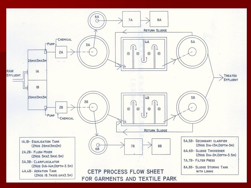
Case Study: Common Effluent Treatment Plant (CEPT) for proposed Garment and Textile Park, Maheshtala
Total Unit: 292 Unit handling 225 kg/day = 159 Unit handling 450 kg/day =138 Water requirement for 159 units 225 kg/day X 50 lts/kg X 159 = lts/day Water requirement for 138 units = 450 kg/day X 50lts/kg X 138 = lts/day

17
Case Study: Common Effluent Treatment Plant (CEPT) for proposed Garment and Textile Tank, Maheshtala (Contd.) Industrial water requirement = lts/day Adding 7.5 % extra, Industrial Waste Water = lts/day Waste Water generation (90% of Water requirement) = 4.80 MLD Domestic sewage generation = 0.20 MLD ETP design capacity = 5.0 MLD
 = 4.80 MLD. Domestic sewage generation. = 0.20 MLD. ETP design capacity. = 5.0 MLD.")
18
Characteristics of raw wastewater for different dying units
Average Characteristics of Units Sl. No Parameters Unit I Unit II Unit III Average 1 pH 9.5 9.2 10.5 9.73 2 COD mg/L 554 915 1025 831 3 BOD mg/L 270 470 552 431 4 TSS mg/L 300 280 220 267

19
Unit Design 1. Volume of Equalization Tank = 834 m3
Size = 26 m X 13 m X 3 m 2. Chemical mixing flush Tank Detention time = 120 sec Size = 3 m X 2.5 m X 1.5 m Chemical to be added: Alum = 300 mg/L PAC = 150 mg/L Lime = 60 mg/L

20
Primary Clarifier ( 2 Nos )
Diameter = 14 m Depth = 3.5 m Over flow rate = 25 m3 /m2/day Detention time = 4.2 hrs Weir loading rate = m3/m/day

21
Aeration Tank (Baffeled-4.5m wide) ( 2 Nos )
Length = 18.7 m Breath = 16.4 m Depth = 3.5 m Detention time = 8hrs F/M ratio = 0.24 MLSS = 3000 mg/L Surface aerator = 4 HP Diffused Aeration System : In addition

22
Secondary Clarifier ( 2 Nos )
Diameter = 13 m Depth = 3 m Detention time = 3.16 hrs Surface over flow rate = 3.16 hrs Sludge Thickener ( 2 Nos ) Gravity thickener with Continuous flow type Two thickeners of 2 m diameter and 3 m depth are to be provided Vacuum filter ( 2 N0s ) Two vacuum filters to operate at 10 kg/m2/hr Land Requirement to treat 5 MLD effluent : 4500 sq.m.( 500 sq.m/MLD)
 Gravity thickener with Continuous flow type. Two thickeners of 2 m diameter and 3 m depth are to be provided. Vacuum filter ( 2 N0s ) Two vacuum filters to operate at 10 kg/m2/hr. Land Requirement to treat 5 MLD effluent : 4500 sq.m.( 500 sq.m/MLD)")
24
Conclusion The ETP for treatment of dye effluent need to be designed on the basis of treatability test atleast in bench scale level. Both chemical and biological treatment are to be carried at bench scale level Chemical doses are to be finalised as per raw effluent quality The bio-reactor is to be stabilized with specific biomass in dye effluent Design F/M ratio, MLSS, MLVSS, D.O, sludge wasting, return sludge etc. are to be maintained during operation of ETP

25
Conclusion( Contd.) Wastewater quality monitoring and surveillance are to be carried out regularly Tertiary treatment with different filtration system may be adopted as per requirement Proper housekeeping should be maintained in the ETP The Plant Operators / Supervisors must be trained

26
THANK YOU

Similar presentations


>")
 Secondary: BOD treatment (biological) Tertiary: Effluent polishing, Nutrient and Toxins Removal.>")
 to avoid oxygen depletion in the recipient Microbial action Aerobic/anaerobic microorganisms.>")


 to oxidise the organic.>")


