Download presentation
Presentation is loading. Please wait.

1
WiMax RF chip Design April 9, 2007 Ali Fotowat, PhD. Managing Director
KavoshCom Asia R&D April 9, 2007 1

2
Outline What is WiMax Is 3G dead? No way. Basic WiMax RF Specs RF System level analysis Multiband front-end, filter, Tx design Quadrature errors Quadrature calibration Remaining Subcarrier Errors Conclusions

3
Issues

4
Issues

5
Issues

6
(source: Worldwide Interoperability for Microwave Access Forum)
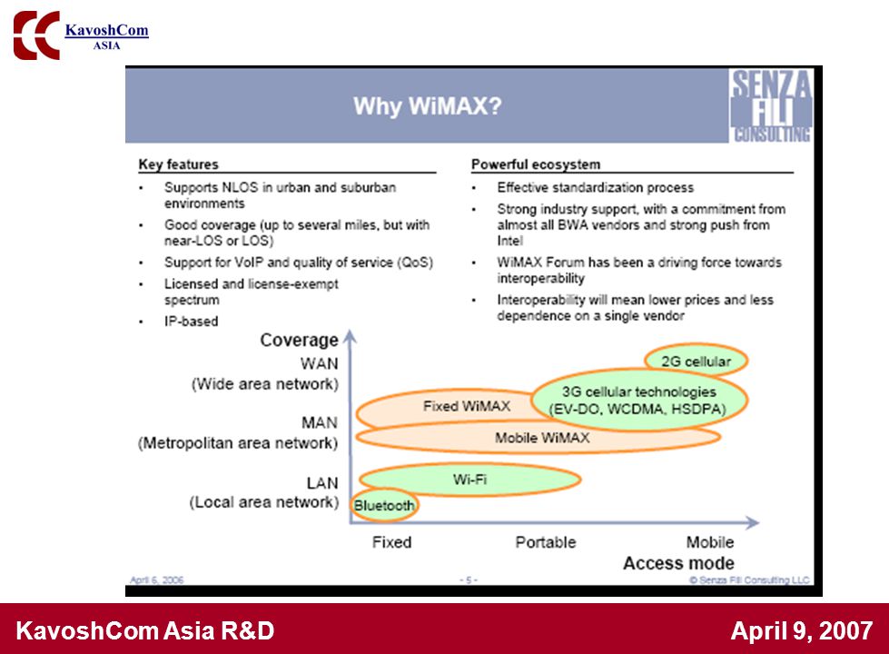
Wireless Technologies (source: Worldwide Interoperability for Microwave Access Forum)
")
7
Mobility vs. User/Link Bit rate Mbps
Wireless Standards Mobility vs. User/Link Bit rate Mbps

8
What is WiMax? WIMAX stands for Worldwide Interoperability for Microwave Access WiMAX refers to broadband wireless networks that are based on the IEEE standard, which ensures compatibility and interoperability between broadband wireless access equipment WiMAX, which will have a range of up to 31 miles, is primarily aimed at making broadband network access widely available without the expense of stringing wires (as in cable-access broadband) or the distance limitations of Digital Subscriber Line.
 or the distance limitations of Digital Subscriber Line.")
9
IEEE Specifications 802.16a Uses the licensed frequencies from 2 to 11 GHz Supports Mesh network 802.16b Increase spectrum to 5 and 6 GHz Provides QoS( for real time voice and video service) 802.16c Represents a 10 to 66GHz 802.16d Improvement and fixes for a 802.16e Addresses Mobile needs Enable high-speed signal handoffs necessary for communications with users moving at vehicular speeds
 c. Represents a 10 to 66GHz d. Improvement and fixes for a e. Addresses Mobile needs. Enable high-speed signal handoffs necessary for communications. with users moving at vehicular speeds.")
10
Issues

11
Issues

12
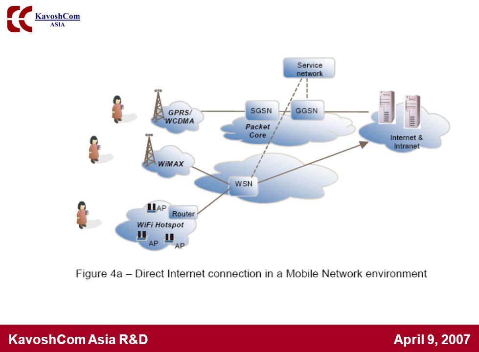
802.16 Backhaul for Business 802.11 Non Line of Sight
Point to Multi-point Point to Point BACKHAUL 802.11 Telco Core Network or Private (Fiber) Network FRACTIONAL E1/T1 for SMALL BUSINESS E1/T1+ LEVEL SERVICE ENTERPRISE INTERNET BACKBONE
 Network. FRACTIONAL E1/T1 for SMALL BUSINESS. E1/T1+ LEVEL. SERVICE ENTERPRISE. INTERNET. BACKBONE.")
13
Point to Point BACKHAUL Telco Core Network or Private (Fiber) Network
Consumer Last Mile Non Line of Sight Point to Multi-point OUTDOOR CPE Point to Point BACKHAUL 802.11 & INDOOR CPE Telco Core Network or Private (Fiber) Network INTERNET BACKBONE
 Network. INTERNET. BACKBONE.")
14
Telco Core Network or Private (Fiber) Network
802.16e Nomadic / Portable Non Line of Sight Point to Multi-point Line of Sight BACKHAUL 802.16e 802.16e PC Card Telco Core Network or Private (Fiber) Network Laptop Connected Through e SEEKS BEST CONNECTION INTERNET BACKBONE 2 to 3 Kilometers Away
 Network. Laptop Connected. Through e. SEEKS BEST. CONNECTION. INTERNET. BACKBONE. 2 to 3 Kilometers Away.")
16
Issues

19
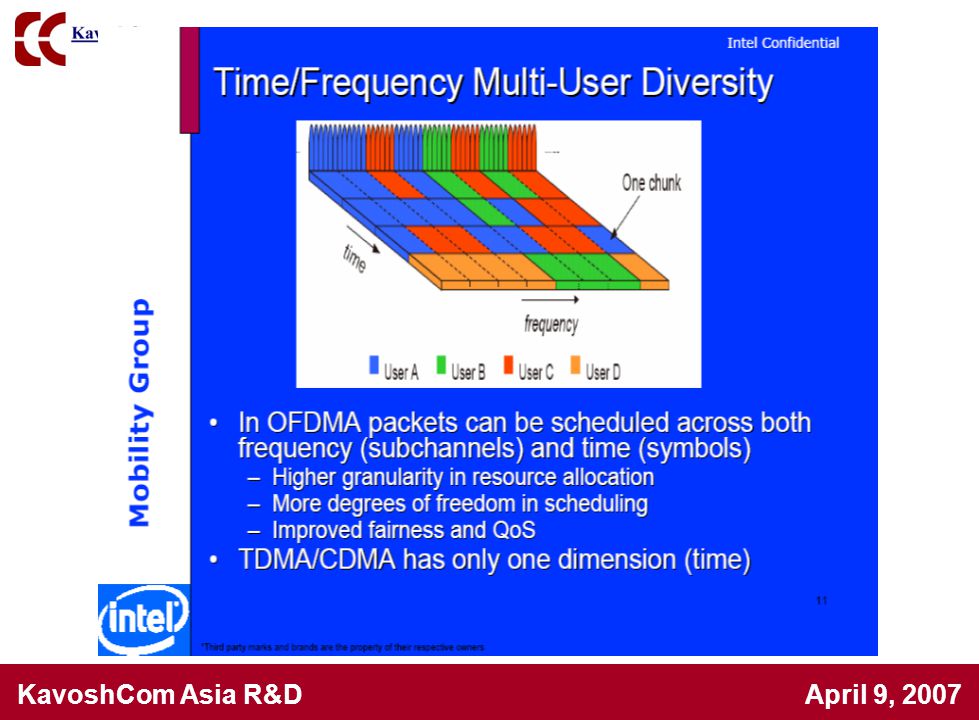
Adaptive Modulation

22
Issues

27
Key Advantages of Mobile WiMax to 3G
Tolerance to Multipath and Self-Interference Scalable Channel Bandwidth Orthogonal Uplink Multiple Access Support for Spectrally-Efficient TDD Frequency Selective Scheduling Fractional Frequency Reuse Fine Quality of Service (QoS) Advanced Antenna Technology
 Advanced Antenna Technology.")
28
Outline What is WiMax Is 3G dead? No way! Basic WiMax RF Specs RF System level analysis Multiband front-end, filter, Tx design Quadrature errors Quadrature calibration Remaining Subcarrier Errors Conclusions

29
Issues

30
Issues

31
Issues

32
Issues

34
The shared channel concept

35
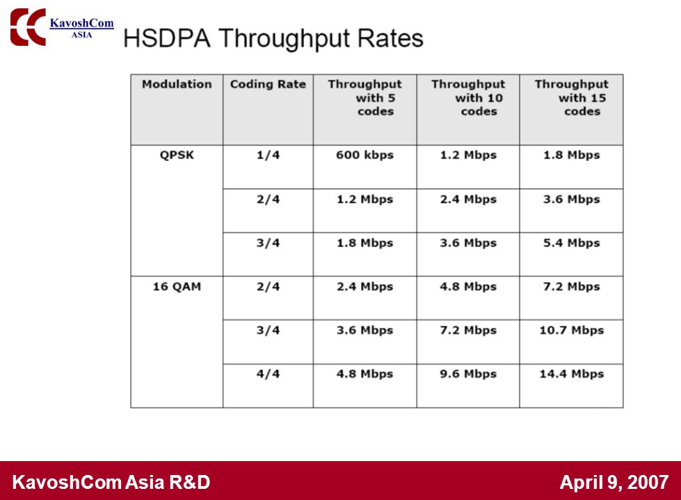
Key ideas in HSDPA The HSDPA concept is based on the following features: Shared channel transmission Higher-order modulation Short transmission time interval (TTI) Fast link adaptation Fast scheduling Fast hybrid automatic-repeat-request (ARQ).
 Fast link adaptation. Fast scheduling. Fast hybrid automatic-repeat-request (ARQ).")
36
Reduced latency Short TTI (Transmission time interval)
Channel codes from the shared code resource are dynamically allocated every 2 ms or 500 times per second. A short TTI reduces roundtrip time and improves the tracking of channel variations—a feature that is exploited by link adaptation and channel- dependent scheduling.

37
Code sharing for shared channel
Shared channel transmission HS-DSCH is based on shared-channel transmission, which means that some channel codes and the transmission power in a cell are seen as a common resource that is dynamically shared between users in the time and code domains. The shared code resource onto which the HS-DSCH is mapped consists of up to 15 codes. The spreading factor (SF) is fixed at 16.
 is fixed at 16.")
38
Issues

39
Increase average speed by serving channels that can be best served!!

40
Issues

41
Issues QPSK, 16QAM

42
Issues

43
Hybrid Automatic Repeat Request

44
Issues

45
HSDPA Mutli-User Diversity
High data rate Low data rate Efficient scheduler

46
Issues

47
Outline What is WiMax Is 3G dead? No way! Basic WiMax RF Specs RF System level analysis Multiband front-end, filter, Tx design Quadrature errors Quadrature calibration Remaining Subcarrier Errors Conclusions

48
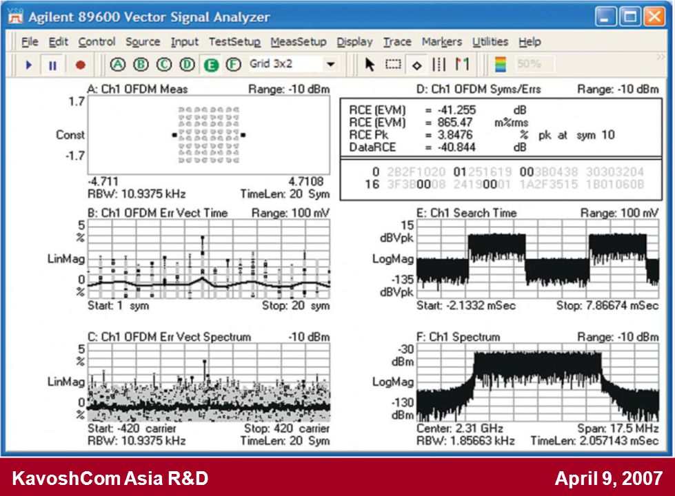
Transmitter test set-up

49
Transmitter requirements
(IEEE , 8.5.2) Transmit power level control Transmit spectral flatness Transmit constellation error Transmit spectral mask ACPR, maximum output power, spurious and harmonics are also important
 Transmit power level control Transmit spectral flatness Transmit constellation error Transmit spectral mask. ACPR, maximum output power, spurious and. harmonics are also important.")
50
Transmitter Spectral Flatness
Spectral lines Spectral flatness Spectral lines from -50 to -1 and +1 to +50 +/--2 dB from the measured energy averaged over all active tones Spectral lines from -100 to -1 and +1 to +100 +2dB/--4dB from the measured energy averaged over all active tones Adjacent subcarriers +/--0.1dB

51
Transmitter Constellation Error
Burst type Relative constellation error (dB) BPSK-1/2 -13.0 QPSK-1/2 -16.0 QPSK-3/4 -18.5 16QAM-1/2 -21.5 16QAM-3/4 -25.0 64QAM-2/3 -28.5 64QAM-3/4 -31.0
 BPSK-1/ QPSK-1/ QPSK-3/ QAM-1/ QAM-3/ QAM-2/ QAM-3/")
52
Receiver test set-up

53
Receiver requirements are defined in
IEEE section Receiver sensitivity Receiver adjacent and alternate channel rejection Receiver maximum input signal Receiver maximum tolerable signal Receiver image rejection

54
Receiver Sensitivity (dBm) for 10e-6 BER
Modulation type and coding rate Bandwidth 64QAM 16QAM QPSK BPSK 3/4 2/3 1/2 -75.7 -72.7 -69.8 -68.1 -65.0 24.4 -77.4 -74.4 -71.3 -66.7 22.7 -81.9 -78.9 -78.8 -74.3 -71.2 18.2 -83.7 -80.7 -77.6 -76.1 -73.0 16.4 -88.9 -85.9 -82.8 -81.3 -78.2 11.2 -90.7 -87.7 -84.6 -83.1 -80.3 9.4 -93.7 -87.6 -86.1 -83.0 6.4 1.75MHz 3.5MHz 7.0MHz 10.0MHz 20.0MHz Rx SNR (dB)
")
56
Outline What is WiMax Is 3G dead? No way! Basic WiMax RF Specs RF System level analysis Multiband front-end, filter, Tx design Quadrature errors Quadrature calibration Remaining Subcarrier Errors Conclusions

57
Examples of Implementation Trials
Almost all of the implementations use Direct Conversion method Direct Conversion pros and cons: Advantages: High level of integration Low power consumption Disadvantages: DC offset problem Higher flicker noise Poor quadrature matching

58
For WLAN / WiMAX [B. Farahani-05]
Direct Conv Architecture For WLAN / WiMAX [B. Farahani-05]
![For WLAN / WiMAX [B. Farahani-05]](http://slideplayer.com/slide/3361583/12/images/58/For+WLAN+%2F+WiMAX+%5BB.+Farahani-05%5D.jpg "Direct Conv Architecture. For WLAN / WiMAX [B. Farahani-05]")
59
Frequency Synthesizer Specifications [B. Farahani-05]
Direct Conv Architecture Frequency Synthesizer Specifications [B. Farahani-05] 1.The phase noise requirement for PLL : offset frequency 2.The settling time should be better than: 5µs
![Frequency Synthesizer Specifications [B. Farahani-05]](http://slideplayer.com/slide/3361583/12/images/59/Frequency+Synthesizer+Specifications+%5BB.+Farahani-05%5D.jpg "Direct Conv Architecture. Frequency Synthesizer Specifications [B. Farahani-05] 1.The phase noise requirement for PLL : offset frequency. 2.The settling time should be better than: 5µs.")
60
Block Requirements for Direct Conversion WiMAX Receiver [B
Block Requirements for Direct Conversion WiMAX Receiver [B. Farahani-05]

61
Block Requirements for Direct Conversion WiMAX Receiver [B
Block Requirements for Direct Conversion WiMAX Receiver [B. Farahani-05]

62
Different signal levels in Zero-IF receiver for WiMAX system [B
Different signal levels in Zero-IF receiver for WiMAX system [B. Farahani-05]

63
Outline What is WiMax Is 3G dead? No way! Basic WiMax RF Specs RF System level analysis Multiband front-end, filter, Tx design Quadrature errors Quadrature calibration Remaining Subcarrier Errors Conclusions

64
Good idea to support both WiMax and WLAN
WiMAX needs are more stringent than WLAN: Tx EVM requirement is smaller for WiMAX Because of Higher number of subcarriers in WiMAX OFDM, Phase noise of the VCO should be smaller for WiMAX which is on the order of 1˚ at arbitrary channel centers I/Q sideband rejection requirement is more stringent than WLAN which is of the order of 35dB. To cover different BW in WiMAX, programmable analog channel selection filters are required

65
Multi-band RF front-end for 4G WiMAX and WLAN applications [C
Multi-band RF front-end for 4G WiMAX and WLAN applications [C.Garuda-06] Direct Conversion Receiver Multi band including: GHz, GHz, GHz Two stage & programmable LNA instead of wideband LNA The gain of dB approximately constant for all bands Utilizes Gilbert cell as a mixer No report about synthesizer and filters In 1.8v IBM 0.18µm CMOS process.

66
Two stage wide-band programmable LNA

67
Performance summary

68
Dual-band GHz, GHz, 0.18µm CMOS Transceiver for a/b/g and d/e(WiBro) [I.Vassiliou, et.al, Broadcom-06] Direct Conversion double band transceiver is fabricated in a 0.18µm 1P6M CMOS Fractional-N synthesizer achieves 0.6˚(0.7˚) integrated phase error at 5GHz (2.4GHz) Digital calibration eliminates I/Q mismatch and carrier leakage Programmable BW filters are used Achieves EVM of -35dB in both transmit and receive paths Achieves sideband suppression better than 45 dB & LO leakage lower than -30dBc
![Dual-band GHz, GHz, 0.18µm CMOS Transceiver for a/b/g and d/e(WiBro) [I.Vassiliou, et.al, Broadcom-06]](http://slideplayer.com/slide/3361583/12/images/68/Dual-band+GHz%2C+GHz%2C+0.18%C2%B5m+CMOS+Transceiver+for+a%2Fb%2Fg+and+d%2Fe%28WiBro%29+%5BI.Vassiliou%2C+et.al%2C+Broadcom-06%5D.jpg "Direct Conversion double band transceiver is fabricated in a 0.18µm 1P6M CMOS. Fractional-N synthesizer achieves 0.6˚(0.7˚) integrated phase error at 5GHz (2.4GHz) Digital calibration eliminates I/Q mismatch and carrier leakage. Programmable BW filters are used. Achieves EVM of -35dB in both transmit and receive paths. Achieves sideband suppression better than 45 dB & LO leakage lower than -30dBc.")
69
System Architecture uses TDD

70
GM-C filter and its OTA enable continuous tuning either 2-15 MHz or 10-25MHz

71
Programmable RF amplifier

72
Rx EVM vs. input power for different bands

73
Measured performance summary

74
5 GHz Dual-Mode WiMAX/WLAN Direct Conversion Receiver [Y. Zhou, Instit
5 GHz Dual-Mode WiMAX/WLAN Direct Conversion Receiver [Y. Zhou, Instit. for Infocom Res-06] Direct Conversion architecture The dual-mode receiver is fabricated in a 0.25µm IBM BiCMOS6HP SiGe process The frequency synthesizer uses VCO running at half the RF frequency to help reduce dc offset due to LO feedthrough DC offset calibration is performed on chip The receiver employs GM-C base-band filter with tunable cut-off frequency of either 5 or 10 MHz The chip adopts a 3 wire serial bus interface to control all the functions The chip consumes 360mW from 3V power supply Two mode double gain LNA is used

75
VCO with Auto Calibration Circuit
Frequency fine tuning is achieved by hyper-abrupt varactor An auto calibration circuit is implemented to select the appropriate band based on process variations

76
Performance Summary

77
A 2.4GHz Direct Conversion Transmitter for
Wimax Applications, C. Masse, Analog Devices Old article but explains the integration problems

78
The I & Q analog baseband
Signal Generation Dual 14-bit DAC IQ modulator. direct up-conversion at the RF frequency remove the alias at multiples of the sampling frequency Low-pass Filters external fractional-N synthesizer LO (a continuous signal with minimal Phase error) VGA with about 50dB of gain control range. amplify or attenuate the composite RF signal out of the modulator Precise output power control is achieved. RMS power detector
 VGA with about 50dB. of gain control range. amplify or attenuate the composite RF signal out of the modulator. Precise output power. control is achieved. RMS power detector.")
79
A direct up-conversion architecture is attractive because:
Wimax OFDM has no active sub-carrier at the origin, direct up-conversion produces less mixing product spurs Requires fewer filters which is important when dealing with such wideband signals The lower number of parts helps minimize the current consumption.

80
Performance Summary WiMax OFDM modulation used here is a10MHz, 64QAM, 256-OFDM signal

82
A CMOS transmitter front-end with digital power control for WiMAX 802
A CMOS transmitter front-end with digital power control for WiMAX e applications Y.H. Liu, H.C. Chen

83
VGA First Stage of VGA: Second Stage of VGA: Totally:
The gain control is realized with a current steering structure Second Stage of VGA: The primary coil of the on-chip transformer serves as the load inductor for a differential-to-single-ended conversion Totally: 16 gain steps are achieved

84
Outline What is WiMax Is 3G dead? No way! Basic WiMax RF Specs RF System level analysis Multiband front-end, filter, Tx design Quadrature errors Quadrature calibration Remaining Subcarrier Errors Conclusions

85
Slides 85-107 in this section based on Dr. Earl McCune’s presentation
Complexities in Quadrature signal generation for OFDM Transmitters and Receivers What is Quadrature Modulation? First-Order Error Sources Individual Effects of error sources Proposed New Calibration Procedure Slides in this section based on Dr. Earl McCune’s presentation

86
Quadrature Modulator Converting the quadrature modulation equation as a block diagram gives the familiar form

87
Realistic QM Model There are nine different first-order error terms

88
Realistic QM Math Gain mismatch & Quadrature error Carrier leakages
Data leakages DC offsets

89
‘Ideal’ Error Values

90
Individual Error Analyses
Modulation offsets Carrier Offsets Modulation gain errors Carrier magnitude errors LO quadrature error Modulator output compression

91
Standard - Use SSB Case A simple, constant-envelope signal (LSB is shown)
")
92
Modulation (I,Q) Offsets
Cause carrier leakage AM also results

93
Carrier Offsets No effect on RF spectrum data leakage present
amplitude variations on output signal

94
Modulation Gain Errors
Causes image sideband AM at double the ‘data’ frequency

95
Carrier Magnitude Errors
Carrier magnitude mismatch - looks identical to IQ gain mismatch

96
LO Quadrature Error Causes image sideband
AM is phase shifted from gain-mismatch cases

97
Output Compression P1dB effect on QM output
gain mismatch case data leakage case P1dB effect on QM output adds intermodulation sidebands

98
Proposed CAL Procedure
Minimize interactivity among adjustments Based on simple SSB signal Five steps (in order!): null data leakage null carrier leakage zero quadrature error match path gains set signal level (for signals with AM)
: null data leakage. null carrier leakage. zero quadrature error. match path gains. set signal level (for signals with AM)")
99
Error-Combination Case
data leakage RF signal

100
Begin with ideal modulator SSB drive signals
1. Ideal Modulator Drive Begin with ideal modulator SSB drive signals

101
2. Null Data Leakage Zero the carrier offset terms OC and OS
RF signal Zero the carrier offset terms OC and OS

102
3. Null Carrier Leakage Adjust data offsets
tradeoff until carrier is nulled RF signal

103
4. Minimize Image Sideband
Adjust quadrature error image sideband minimizes at fe = 0 may need 0.1 dB resolution RF signal

104
5. Match Path Gains Adjust one data-gain term (choose AI, for example)
null the image sideband compression distortion also disappears RF signal

105
6. Set Overall Gain Apply I(t) and Q(t) for an envelope-varying signal
Turn down gains AI and AQ together to drop sidebands effects a backoff from the P1dB of the summer

106
Limited-Access Bounds
If full access to all error terms is not available, then the achievable performance will be limited. Ex. : quad error limitation (no access to quadrature error) 1 degree 2 degrees
 1 degree. 2 degrees.")
107
Conclusions Quadrature modulation is a rectangular (Cartesian) method of implementing signals Real Quadrature-Modulators are not as simple as the textbooks (or databooks!) claim Quadrature modulators can be tamed if all ports are available to the design engineer Output Noise Figure is a major problem Linear modulations tend to require large output (and input) backoffs All error terms are, in general, functions of temperature!
 claim. Quadrature modulators can be tamed if all ports are available to the design engineer. Output Noise Figure is a major problem. Linear modulations tend to require large output (and input) backoffs. All error terms are, in general, functions of temperature!")
108
Outline What is WiMax Is 3G dead? No way! Basic WiMax RF Specs RF System level analysis Multiband front-end, filter, Tx design Quadrature errors Quadrature calibration Remaining Subcarrier Errors Conclusions

109
How much spur rejection is needed?
For 45 dB rejection, the gain matching should be better than 0.1 dB and the phase matching better than 0.5 degree. Some manufacturers require better than 55 dB for individual blocks!

110
ASt cos(wStt) + AWe cos (wWet)
Strong and weak duo ASt cos(wStt) + AWe cos (wWet) A two tone signal in time domain.
 + AWe cos (wWet) A two tone signal in time domain.")
111
A quadrature transmitter overall block diagram

112
Transmitter features Allow offset adjustment blocks at the inputs
A programmable low pass filter corner frequency for all WiMax needs Baseband gain with G adjustment (1 dB range in 0.1 dB resolution) Control on the local oscillator phase (3 degree range with 0.1 degree control) A very linear transmit mixer A very linear combiner A programmable attenuator (20 dB range in 1 dB steps) An integrated power level detector
 Control on the local oscillator phase (3 degree range with 0.1 degree control) A very linear transmit mixer. A very linear combiner. A programmable attenuator (20 dB range in 1 dB steps) An integrated power level detector.")
113
Strong and weak duo is not a duo!
f Strong 3rd Harmonic Weak 3rd Harmonic Undesired sideband Desired sideband LO feed-through A typical shape of spectrum out of a quadrature transmitter

114
LO feed through minimization process
4 MHz LO Feed- through Use a 4 MHz baseband tone. Reduce the input level so that the upper side band is more than 60 dB down or into the noise level. The detector gives a 4 MHz LO feed-through, and a 8 MHz upper side band. Use a low frequency bandpass filter to detect the LO feed-through Adjust offset controls till lo feed-through is minimized (2 dimensional search)
")
115
The Side-band minimization process
f 4 MHz Minimized LO feed-through Undesired sideband Desired sideband Change the input frequency to 2 MHz In crease the input level. The LSB and USB will both increase. The detector detects a 4MHz USB, a 8 MHz USB 3rd harmonic. The 4 MHz LSB 3rd harmonic falls on the undesired signal! Adjust G and to minimize the USB. The rejection is limited by the 3rd harmonic levels which is set by the transmit mixer

116
Outline What is WiMax Is 3G dead? No way! Basic WiMax RF Specs RF System level analysis Multiband front-end, filter, Tx design Quadrature errors Quadrature calibration Remaining Subcarrier Errors Conclusions

117
Will this calibration work across the band?
In single carrier systems single frequency interference and even non-flat noise spectrum can be tolerated. In OFDM systems S/N has to be fixed across the band Optimum G and do not stay the same vs. frequency! What are the sources of the error vs. frequency?

118
Edge of the band matching in filters
C+C R+R Q Iout Qout In a 1st order filter 0.5% mismatch in components results in 1.14 degree phase error at the edge of the band. In a 5th order filter assuming random component values the expected phase error will be 3.6 degrees at the edge of the band.

119
OFDM base-band spectrum
Filter gain response Filter phase response System gain mismatch System phase mismatch OFDM base-band spectrum

120
Broadband gain mismatch compensated by G but residual gain error still at the band edge!
Broadband phase mismatch compensated by control with LLL, but residual phase error still at the band edge!

121
DSP Att. Poly I Q Sin VGA j Ortho. Tester BB filter The solution is using base-band filter loop back techniques and saving frequency dependent calibration values in the DSP

122
Outline What is WiMax Is 3G dead? No way! Basic WiMax RF Specs RF System level analysis Multiband front-end, filter, Tx design Quadrature errors Quadrature calibration Remaining Subcarrier Errors Conclusions

123
What did we learn? WiMax is the best the telecom technology offers, but 3G is in hot pursuit! The testing methodology to separate the RF and DSP designers is very critical. Direct Conv. with new VCO/synthesizer techniques is the way to go. The Quadrature calibrations issues are the key to success. 123

Similar presentations


 Transmitters>")
 Carrier Wave Modulation Systems.>")
 ANGLE MODULATION>")
>")


 the third generation mobile communication systems.>")


