Download presentation
Presentation is loading. Please wait.

1
Team Members: Alyssa KennettEE Charles VeronneauEE Chris DiLalloME Christian KaszasME Kerry KlauderME Nick SaccoME Faculty Mentor: Robert Jenkins Company Contacts: Jim Peterson and Jon Funk Neuton Lawn Tractor Project

2
Short Intro to the Project Starting Out: Mechanically driven lawn mower with mechanical steering system and gas power Finish Line Product: Battery powered and electrically driven lawn mower with electronic steering and controls system. BEFOREAFTER

3
Final Project

4
Project Goals Electrically driven, powered, and controlled Neuton Mower Redesign steering Environmentally friendly Increase consumer appeal 2 hour run time

5
Original Framework - Eliminate mechanical systems found in current gas tractors - Powered by batteries without gasoline - Appealing aesthetics - Consumer market: 45-55 year old, predominantly male - Designed to mow a 1 acre lawn - Mow time: 2 hours - Low noise level - Redesigned Steering - Efficient mowing - Easy maintenance unlike current gas tractors - Safety

6
Unexpected Obstacles Battery size not as specified Motor mounting position awkward pulley assembly Bearings order not fully processed Wiring Difficulty

7
Discarded Concepts Pancake Motors – weight on deck Hub Motors - cost Steering Wheel – complexity Independent Battery Systems - no need for separation between systems, more batteries Split-axle System – Fabrication difficulty Hand-made motor controller – complexity, heat sinks, difficulty sourcing capable components

8
Main Features/Components Framework Drive Train Motors Batteries Controls Wiring

9
Framework Modifications Rear/Side Battery Shelves Control Arms Mounting Block for Blade Motor

10
Side Battery Shelves Located on left and right side 1-inch walls to hold battery in place Full wall against tractor Full back wall at wheels

11
Rear Battery Shelves Mount above drive motors Holds two batteries

12
Control Arms Mounted to battery shelves Both control arms hold a joystick Right side also holds main user controls: key start, kill switch, on/off key switch for blades

13
Mounting Block for Blade Motor Holds blade motor upright Support for battery shelf Constructed out of aluminum

14
Drive Train Options Original Possibilities Existing Hydraulic Drives Direct Drive Hub Motors Standard Motors Pulley System Roller Chain V Belts Synchronous Belts Solely Electric Driven Cost Support, Placement Weight, Noise Slippage Reasons for Decisions 2 Step Pulley System Increase in torque, decrease in RPM required 15.5:1 ratio Outer Diameter of V belt pulley on the order of the diameter of tire Synchronous belts of such ratios not available 2 Stages allows for 2 4:1 ratios Provide required strength with no slipping

15
Pulley System

16
Split Axle 2 Axles, supported in center by inverted block bearings Drawback: Difficult fabrication process Existing Hydraulic Casings Cases already known to have support strength No fabrication required* Allows use of existing parking break *Hydraulics were removed and stripped of any parts not used by parking break Support System

17
Extending the Wheel Base Tire overhang causes interference for mounting a pulley on the hub axle Solution: Extend the Wheel Base Adding an 2.5 inch extension to the hub clears the hub axle for mounting of a pulley Hub Spacers

18
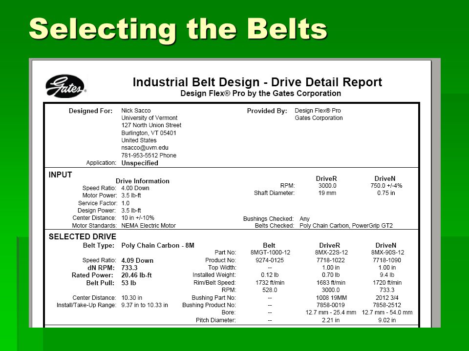
Corporate Headquarters in Canton, Massachusetts Store in Williston, Vermont Canton location recommended use of Gates Design Flex® Selecting the Belts

20
Belts and Pulleys Selected From end mounted motor: P-22-8MGT-12, P-90-8MGT-12 pulleys 1104-8MGT-12 belts From forward mounted motor: P-22-8MGT-12, P-90-8MGT-12 pulleys 840-8MGT-12 belts To wheels: P-24-8MGT-12, P-90-8MGT-12 pulleys 920-8MGT-12 belts

21
Motors Overview 2 Drive Motors 1 Blade Motor 1.5 kW, 24V Permanent Magnet DC Motors Full Torque per wheel (70 N-m) Regulations, Standards, Safety Bidirectional, TEFC 80 Amp @ FL 4 AWG and 10 AWG
 Regulations, Standards, Safety Bidirectional, TEFC 80 FL 4 AWG and 10 AWG")
22
Torque Calculations Calculations Top Speed (V): 8.5 mph Time to reach top speed (t): 5 seconds Wheel radius (r):.667 feet Angle to ascend (θ): 6° Assumed Weight (W): 730 pounds 24 pound mass Flat Ground Acceleration (a) = V/t = 2.5 ft/s 2 Required Force # = m*a = 59.6 lbf Required Torque # = F*r = 39.8 ft-lbf Up a Slope at constant speed: Required Force # = m*R*Sin(θ) = 80.5 lbf Required Torque # = F*r = 53.7 ft-lbf # Total force and torque required to move the mass. Full Torque required at each wheel Operator must be able to turn around while on a slope, therefore each wheel alone must provide the necessary power to move the tractor. Required Torque to each wheel is 53.7 foot pounds

23
Motor Output: 3.5 ft-lb Torque 3000 RPM Gear Ratio Calculations Required RPM = Velocity/(2∏r) =178 rpm Required Torque = 53.7 ft-lbf Gear ratio to increase torque: 53.7 / 3.5 = 15.3 Gear ratio to decrease RPM: 3000 / 178 = 16.9 Required torque is for constant speed directed up a slope and is greater than the torque required for flat acceleration, therefore the torque cannot be lowered below 53.7 ft-lbf. RPM and torque raised to accommodate. Gear ratio to increase torque: 54.2 / 4.7 = 15.5 Gear ratio to decrease RPM: 3000 / 194 = 15.5 2 Step Gear Ratios: 54.2 / 4 = 13.55, 13.55 / 4 = 3.4 3000 / 4 = 750, 750 / 4 = 188 2 Gear Ratios of approximately 4 accomplish what a single gear ratio of 15.5 accomplishes Torque Calculations

24
Motor Mounting Blade motor standing upright Drive motors side-by-side Allows for batteries to go on top

25
Power System Overview 4x120 Ah, AGM-SLA Batteries 13”x7”x8.5” = Good Fit Cheapest choice, Deep-cycle, Ample run-time 24V Dual Eagle Pro Charger Capacity to charge all batteries together 25 Amp output can replenish full charge in approx.

26
Controls System Overview 24V, 120A Kelly Controller Contactors for Protection Microcontroller 0-5V Digital output, determines reverse on/off Joysticks 0-5V output, bi-directional, single axis Other Controls Key switch Blade switch Kill switch

27
Motor Controllers Kelly Controller PM motor controllers 120 A continuous, 24 VDC Capable of Reversing Analog input in the range of 0-5V Windows Interface for Programming

28
Microcontroller / DA Conversion PIC16F887 44 pins, converts input to digital Determines reverse on/off, output high/low C compiler compatibility MPLAB IDE C code Simple logic to analyze input Output 0-5V instead of 0-2.5V and 2.5-5V DAC (Digital to Analog Converter) Convert from microcontroller to motor controller
 Convert from microcontroller to motor controller")
29
Simplified Circuitry for Motor Control

30
Joysticks Allow electronic control Hall Effect Sensor ~0-5V output Miniature – need to extend levers

31
Prototype Handles Modeled in Solidworks Increased radius of movement Angled for comfort Ergonomic Grip

32
Body Design Courtesy of Jon Funk

33
Safety Kill Switch Belt Guards Seat Sensor

34
What comes next? Custom designed frame to fit purpose and additional parts Adjustable control arms Adjustable seat height/position New body

35
Future Thoughts Possibility of charging batteries through small wind turbine or solar panels.

36
METALWORKS, Inc. Thank You Jon Funk, Jim Peterson, and Robert Jenkins for design, implementation, direction, and advice Floyd Vilmont

37
Corporate Headquarters in Canton, Massachusetts Store in Williston, Vermont Canton location recommended use of Gates Design Flex® Thank You

38
Questions ? ? ? ? ? ? ? ? ? ?

Similar presentations


 Heather Blaha Matt Fuxa Joey King Michael McConnell Domenic Tassoni.>")


