Download presentation
Presentation is loading. Please wait.

1
PLC - Introduction What does PLC stand for?
PLC - programmable logic controller PLC implements logic control functions by means of a program

2
PLC - Introduction An application example 1: Gate Control PLC can sense a vehicle at the entrance or exit, and open and close the gate automatically The current vehicle count is easily determined by programming a simple counter

3
PLC - Introduction An application example 2: Conveyor System PLC can be used to start/stop latching logic for motor control Counters can be used for monitoring product amounts

4
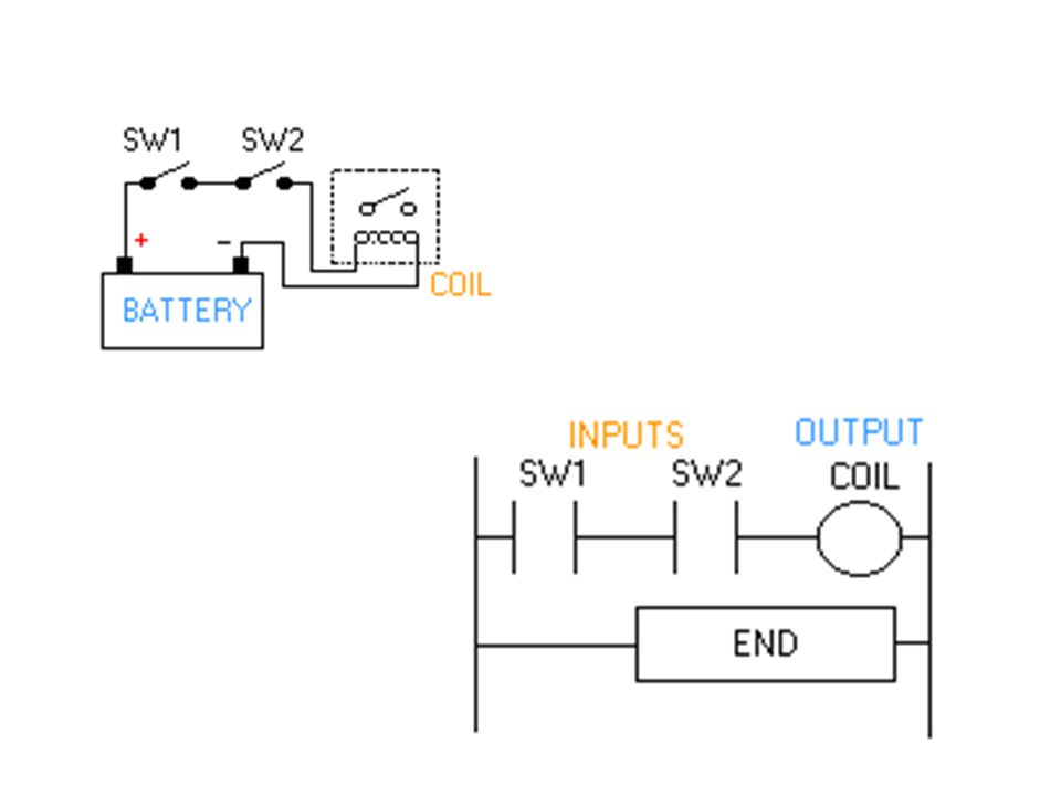
PLC - Introduction Comparing traditional and programmable control systems - 1

5
PLC - Introduction In traditional control, the switches S1, S2 and S3 must close for K1 to be turned on - the wiring makes the rule In PLC systems, the program is written to perform the logic “when S1 is closed AND S2 is closed AND S3 is closed, THEN turn on K1” - the program makes the rule

6
How does a PLC differ from a computer?
PLC - Introduction How does a PLC differ from a computer? A computer is optimized for calculation and display tasks A computer is programmed by specialists A PLC is designed for (logic) control and regulation tasks A PLC is programmed by non-specialists A PLC is well adapted to industrial environment
 control and regulation tasks. A PLC is programmed by non-specialists. A PLC is well adapted to industrial environment.")
7
PLC - Introduction Why are PLCs so common? They are cost-effective They are flexible, reliable and compact They have significant advantages over traditional control systems based on relay or pneumatics

8
PLC - Introduction Where are PLCs used? In every industry where automation is involved, from individual machines to whole processes

9
What tasks do PLCs perform?
The logic control tasks such as interlocking, sequencing, timing and counting (previously undertaken with relays or pneumatics) In addition, PLCs can perform a variety of calculation, communication and monitoring tasks lecture note 9 PLC
 In addition, PLCs can perform a variety of calculation, communication and monitoring tasks. lecture note 9 PLC.")
10
Outputs & Power Supply Communication Ports (RS-485) Inputs
lecture note 9 PLC

11
Structure of a PLC Level of Liquid in Tank lecture note 9 PLC

12
The PLC processor

13
PLC Input/Output Devices

14
Switches (limit switches, level switches, etc.) Sensors ...
PLC Input Devices Push buttons Switches (limit switches, level switches, etc.) Sensors ... PLC Output Devices Relay contacts Solenoid valves Signal devices (such as lamps, alarms, etc.) Motors ... lecture note 9 PLC
 Sensors. ... PLC Output Devices. Relay contacts. Solenoid valves. Signal devices (such as lamps, alarms, etc.) Motors. ... lecture note 9 PLC.")
15
A solid state (electronic) device that controls output devices
based on input signals and a user developed program. Originally developed to directly replace relays used for discrete control. Inputs Output Devices CR PLC (Programmable Logic Controller) What is a PLC? A solid state device that controls output devices based on input signals and a user developed program. Output Device: Any device or equipment that I want to control, that I want to turn on or off, that I want to open or close, that I want to show indication of a situation. Input Device: any equipment that gives the PLC information about the current state of the system (ie. Temperature, speed, position). Input device is also the equipment that an operator uses to tell the PLC what to do. PLC Basics - Automation Fair 2006
 What is a PLC A solid state device that controls output devices based on input signals and a user developed program. Output Device: Any device or equipment that I want to control, that I want to turn on or off, that I want to open or close, that I want to show indication of a situation. Input Device: any equipment that gives the PLC information about the current state of the system (ie. Temperature, speed, position). Input device is also the equipment that an operator uses to tell the PLC what to do. PLC Basics - Automation Fair")
16
Understanding the PLC Operating Cycle
Input Scan START The status of external inputs (terminal block voltage) is written to the Input image (“Input file”). House Keeping Internal checks on memory, speed and operation. Service any communication requests, etc. PLC OPERATING CYCLE Program Scan Each ladder rung is scanned using the data in the Input file. The resulting status (Logic being solved) is written to the Output file (“Output Image”). Output Scan The Output Image data is transferred to the external output circuits, turning the output devices ON or OFF. PLC Basics - Automation Fair 2006
 is written to the Input image ( Input file ). House Keeping. Internal checks on memory, speed and operation. Service any communication requests, etc. PLC OPERATING. CYCLE. Program Scan. Each ladder rung is scanned using the data in the Input file. The resulting status (Logic being solved) is written to the Output file ( Output Image ). Output Scan. The Output Image data is transferred to the external output circuits, turning the output devices ON or OFF. PLC Basics - Automation Fair")
17
What you must consider when selecting a PLC
Inputs/Outputs How many Inputs/Outputs? including embedded, local expansion, and networked I/O 10, 16, 20, 32, 138, 156, >256 How many Discrete vs. Analog Type of I/O AC, DC, Analog, Thermocouple, sourcing, sinking, etc. Communications Networks DF1 Full Duplex, DF1 Half Duplex, DF1 Radio Modem, DH485, ModBus Master / Slave DeviceNet, Ethernet Functions required PID PTO/PWM (Pulse Train Output/Pulse Width Modulated) Data Logging Messaging between PLC’s Math Calculations Memory Size 1k, 6k, 8k 12k, 14k, PLC Basics - Automation Fair 2006
 Data Logging. Messaging between PLC’s. Math Calculations. Memory Size. 1k, 6k, 8k 12k, 14k, PLC Basics - Automation Fair")
18
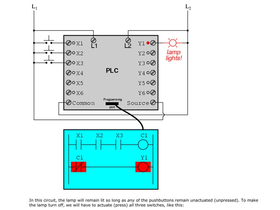
Ladder diagrams are specialized schematics commonly used to document industrial control logic systems They are called "ladder" diagrams because they resemble a ladder, with two vertical rails (supply power) and as many "rungs" (horizontal lines) as there are control circuits to represent. The "L1" and "L2" designations refer to the two poles of a 120 VAC supply,
 and as many rungs (horizontal lines) as there are control circuits to represent. The L1 and L2 designations refer to the two poles of a 120 VAC supply,")
20
Digital Logic Functions
OR AND

21
NOT XOR

22
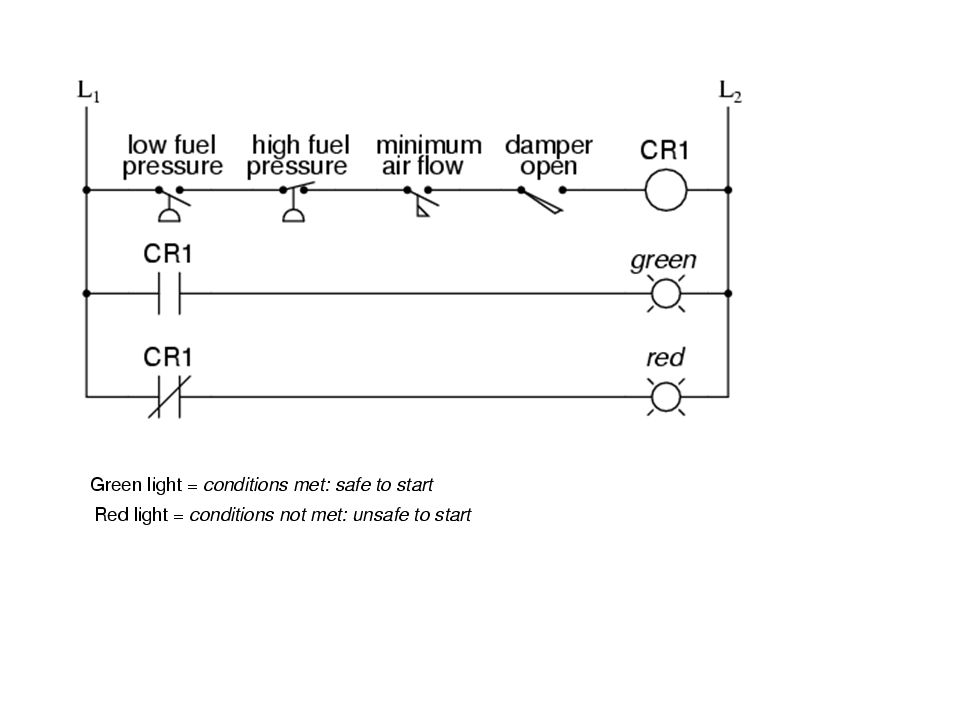
Permissive and interlock circuits
A practical application of switch and relay logic is in control systems where several process conditions have to be met before a piece of equipment is allowed to start e.g. 01. A burner control for large combustion furnaces. In order for the burners in a large furnace to be started safely, the control system requests "permission" from several process switches, including high and low fuel pressure, air fan flow check, exhaust stack damper position, access door position, etc. Each process condition is called a permissive, and each permissive switch contact is wired in series, so that if any one of them detects an unsafe condition, the circuit will be opened

24
e.g. 02. Application of relay logic is in control systems where we want to ensure two incompatible events cannot occur at the same time. An example of this is in reversible motor control, where two motor contactors are wired to switch polarity (or phase sequence) to an electric motor, and we don't want the forward and reverse
 to an electric motor, and we don t want the forward and reverse.")
25
Take note of the normally-closed "OL" contact, which is the thermal overload contact activated by the "heater" elements wired in series with each phase of the AC motor. If the heaters get too hot, the contact will change from its normal (closed) state to being open, which will prevent either contactor from energizing. This control system will work fine, so long as no one pushes both buttons at the same time. If someone were to do that, phases A and B would be short-circuited together by virtue of the fact that contactor M1 sends phases A and B straight to the motor and contactor M2 reverses them; phase A would be shorted to phase B and visa-versa. Obviously, this is a bad control system design!

26
To prevent this occurrence from happening, we can design the circuit so that the energization of one contactor prevents the energization of the other. This is called interlocking, and it is accomplished through the use of auxiliary contacts on each contactor

28
Can you explain following ladder diagrams ?

29
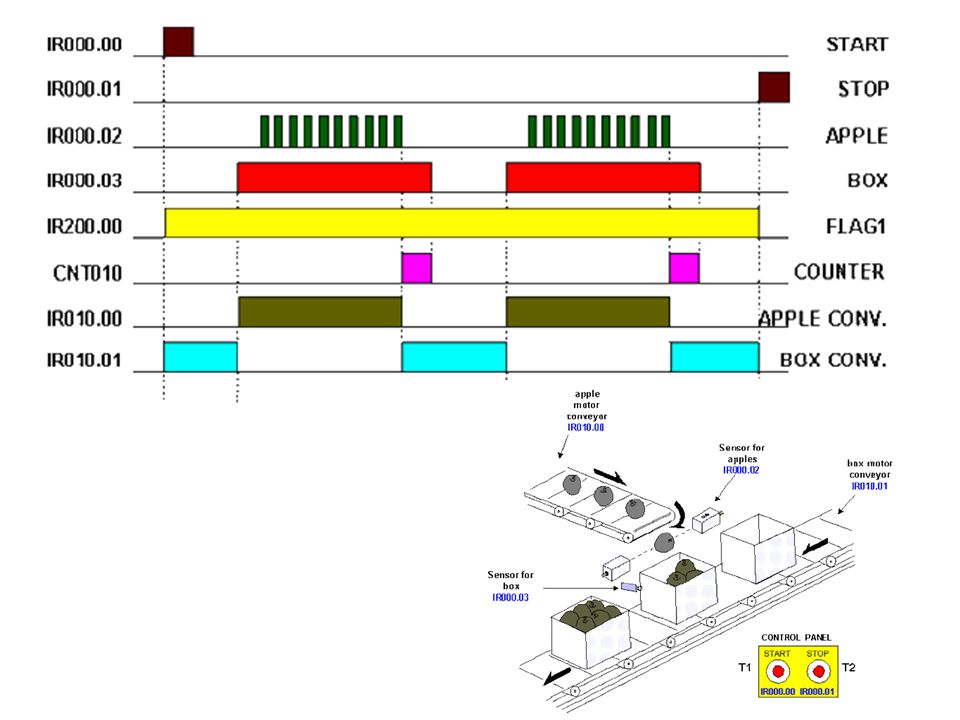
Industry Application:
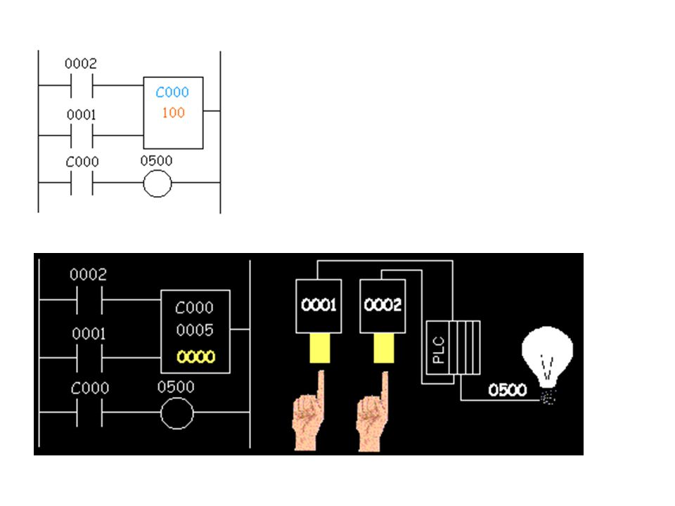
Product packaging is one of the most frequent cases for automation in industry

32
Counters Cxxx is the name of the counter
yyyyy is the number of pulses we want to count before doing something

34
: . Timers

35
An accumulating timer

36
Case1: Ensure two incompatible events cannot occur at the same time. An example of this is in reversible motor control, where two motor contactors are wired to switch polarity (or phase sequence) to an electric motor, and we don't want the forward and reverse contactors energized simultaneously
 to an electric motor, and we don t want the forward and reverse contactors energized simultaneously.")
37
When contactor M1 is energized, the 3 phases (A, B, and C) are connected directly to terminals 1, 2, and 3 of the motor, respectively. However, when contactor M2 is energized, phases A and B are reversed, A going to motor terminal 2 and B going to motor terminal 1. This reversal of phase wires results in the motor spinning the opposite direction. Let's examine the control circuit for these two contactors: Take note of the normally-closed "OL" contact, which is the thermal overload contact activated by the "heater" elements wired in series with each phase of the AC motor. If the heaters get too hot, the contact will change from its normal (closed) state to being open, which will prevent either contactor from energizing.
 state to being open, which will prevent either contactor from energizing.")
38
BUT If someone were to do that ????
system will work fine, so long as no one pushes both buttons at the same time BUT If someone were to do that ???? To prevent this occurrence from happening, use interlocking…. Try………………

39
when M1 is energized, the normally-closed auxiliary contact on the second rung will be open, thus preventing M2 from being energized, even if the "Reverse" pushbutton is actuated. Likewise, M1's energization is prevented when M2 is energized

40
Explain this…. When the "Forward" pushbutton is actuated, M1 will energize, closing the normally-open auxiliary contact in parallel with that switch. When the pushbutton is released, the closed M1 auxiliary contact will maintain current to the coil of M1, thus latching the "Forward" circuit in the "on" state. The same sort of thing will happen when the "Reverse" pushbutton is pressed.

41
Exercise: Explain the following ladder diagram

42
Answer: If the motor has been running in the forward direction, both M1 and TD1 will have been energized. This being the case, the normally-closed, timed-closed contact of TD1 between wires 8 and 5 will have immediately opened the moment TD1 was energized. When the stop button is pressed, contact TD1 waits for the specified amount of time before returning to its normally-closed state, thus holding the reverse pushbutton circuit open for the duration so M2 can't be energized. When TD1 times out, the contact will close and the circuit will allow M2 to be energized, if the reverse pushbutton is pressed. In like manner, TD2 will prevent the "Forward" pushbutton from energizing M1 until the prescribed time delay after M2 (and TD2) have been de-energized.
 have been de-energized.")
43
Leading Brands Of PLC AMERICAN 1. Allen Bradley 2. Gould Modicon
3. Texas Instruments 4. General Electric 5. Westinghouse 6. Cutter Hammer 7. Square D EUROPEAN 1. Siemens 2. Klockner & Mouller 3. Festo 4. Telemechanique JAPANESE 1. Toshiba 2. Omron 3. Fanuc 4. Mitsubishi 43

44
PLC Size 1. SMALL - it covers units with up to 128 I/O’s and memories up to 2 Kbytes. - these PLC’s are capable of providing simple to advance levels or machine controls. MEDIUM - have up to 2048 I/O’s and memories up to 32 Kbytes. 3. LARGE - the most sophisticated units of the PLC family. They have up to 8192 I/O’s and memories up to 750 Kbytes. - can control individual production processes or entire plant. 44

45
Normally Open Pushbutton
Discrete Input A discrete input also referred as digital input is an input that is either ON or OFF are connected to the PLC digital input. In the ON condition it is referred to as logic 1 or a logic high and in the OFF condition maybe referred to as logic 0 or logic low. Normally Open Pushbutton Normally Closed Pushbutton Normally Open switch Normally Closed switch Normally Open contact Normally closed contact

Similar presentations


>")


: Asynchronous Serial Communications, similar in many respects to.>")


