Download presentation
Presentation is loading. Please wait.

1
3D-Dynamic design for reinforced versus prestress concrete for Al-Huriya building Prepared by Nizar Abed Al-Majeed Salameh Mohamed Khaled Abu-Al Huda Supervisor Dr. Imad Al-Qasem

2
CHAPTER ONE INTROUCTION The project is a structural analysis and 3D-Dynamic design of an office building in Ramallah city, known as AL-Huriya, which consists of a seven stories, with 3.5 height except the first floor with 4m story height. The building will be first designed under a static load, after that we will study the building for dynamic, finally a prestress concrete will be used to design the building to compare it with the reinforcement concrete, to conclude many factors that should be taken into consideration in designing any structure. These include economic factors, durability and the safety of its inhabitants.

3
SystemPartF’cfy Reinforced ConcreteSlab250 kg/cm24200 kg/cm2 Beams250 kg/cm24200 kg/cm2 Columns500 kg/cm24200 kg/cm2 Footings250, 500 kg/cm24200 kg’cm2 Prestress Concreteslab6000Psi243Ksi Columns500 kg/cm24200 kg/cm2 Footings250, 500 kg/cm24200 kg/cm2 Materials Live load0.4ton/m 2 Super imposed load0.3ton/m 2 Loads

4
CHAPTER TWO SLAB

5
One way solid slab is used only as slab system Use slab thickness of 17cm, according to deflection requirement In design phase of the slab, there are two strip(1m) taken as a model. W u =1.51 15@3.75m 6@3.75m W u =1.51 Strip I Strip II Loads distribution

6
Strip I Use 4Ф12mm for negative and positive moment Moment distribution Strip II

7
CHAPTER THREE BEAMS Beams in this part of the project will be designed using reactions from beam model in SAP2000. The girder system is used to design the building, and all of the beams are dropped; multi span and large space beams are used in all floors. The system of the building consist of a four beams group (B1, B2, B3, B4) And a two group of girders (G1, G2).
 And a two group of girders (G1, G2)..")
9
Design for Moment Final Results Positive MomentNegative Moment Exterior spansInterior spanInterior supports BeamsDimensionsMnΡAsMnρAsMnρAs B130x8065.610.010225.451.310.00337.6258.760.009122.90 B250x90168.820.011258.883.440.003314.70152.170.011349.06 B350x90183.760.014163.78---129.340.009444.16 B460x100263.260.013378.50------ Final Results Positive MomentNegative Moment Exterior spans1st interior spans2nd interior spans1st interior supports2nd interior supports GirdersDimensionsMnρAsMnρAsMnρAsMnρAsMnρAs G150x90164.240.012353.9751.99.003619.63117.93.008539.25163.620.012353.97141.80.010440.06 G290x100384.780.0129112.54219.22.006964.3162.57.003332.15411.270.0141120.58209.440.006656.27 Moment Design ParameterDimensionsMnAsVnVcVsAvS Unitscmton.mcm 2 ton cm 2 cm

10
Shear Design Design for Shear Final ResultsExterior spansInterior span BeamsDimensionsVnVcVsAvSVnVcVsAvS B130x8031.74618.85512.8901.573521.25018.8552.3951.5735 B250x9080.1035.6144.493.14255435.6118.393.1440 B350x9077.2235.6141.613.142525.1035.6114.8753.1440 B460x10069.6947.7621.433.1445----- Final ResultsExterior spans1 st interior spans2 nd interior span Girders Dimension s VnVcVsAvSVnVcVsAvSVnVcVsAvS G150x9093.4935.6157.883.142075.4435.6139.833.142592.2635.6156.653.1420 G290x100229.171.64157.43.145202.671.641313.14599.5271.6427.883.1445

11
Final Results For positive moment (span)Negative moment (support) BeamExterior1 st interior2 nd interior1 st interior2 nd interior B110Φ183Φ18-9Φ18- B212Φ253Φ25-10Φ25- B313Φ25--9Φ25- B416Φ25---- G111Φ254Φ258Φ2511Φ2510Φ25 G214Φ328Φ324Φ3215Φ327Φ32
Negative moment (support) BeamExterior1 st interior2 nd interior1 st interior2 nd interior B110Φ183Φ18-9Φ18- B212Φ253Φ25-10Φ25- B313Φ25--9Φ25- B416Φ G111Φ254Φ258Φ2511Φ2510Φ25 G214Φ328Φ324Φ3215Φ327Φ32")
12
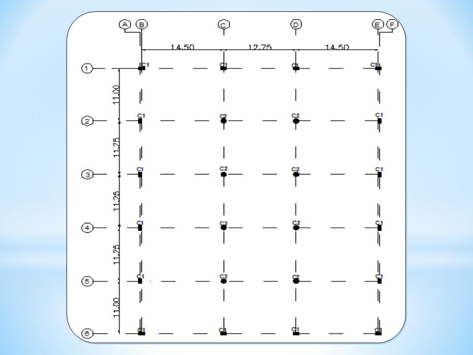
CHAPTER FOUR COLUMNS sixteen columns having a rectangular section, and eight columns having a circular section, will be designed. All the columns in this project are classified into two groups depending on the ultimate axial load and the shape. The ultimate axial load on each column is from the Reaction of beams Columns numberUltimate load(ton) Ultimate loads from seven stories(ton) C1144.241009.68 C260.96426.72 C3179.181254.26 C4452.713168.97 C5287.652013.55 Group (1)C1,C2,C3Rectangular Group (2)C4,C5Circular
 Ultimate loads from seven stories(ton) C C C C C Group (1)C1,C2,C3Rectangular Group (2)C4,C5Circular.")
14
Summary of result Group Pu (ton) Dimensions(h*b)(cm) spirally (D)(cm) ρAs(cm2)# of barsShear reinforcement I1254.26100*500.015276.0416 Φ25mm4 Φ10mm/30cm II3168.97Spiral, D=1000.0206267.4134 Φ32mmΦ10mm(spirally) Final Results
 Dimensions(h*b)(cm) spirally (D)(cm) ρAs(cm2)# of barsShear reinforcement I * Φ25mm4 Φ10mm/30cm II Spiral, D= Φ32mmΦ10mm(spirally) Final Results")
15
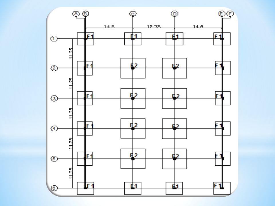
CHAPTER FIVE FOOTING In this chapter the footing will be designed, all footings in this part of the project will be isolated (single) footings. The design will depend on the total axial load carried by each column. Group ID Columns included Loads (ton) Dead loadLive load F1C1,C2,C3726203 F2C4,C51698504 The footings are classified into two groups
 Dead loadLive load F1C1,C2,C F2C4,C The footings are classified into two groups.")
17
Flexure Design X-Y Direction Steel Design Mu =107.12ton.m ρ =0.0023 As =25.62cm 2 As min =21.6cm 2 Use As =25.62cm 2 Bar Diameter25mm # of Bars Needed6 Spacing16.67cm Group F1 Design Use Main Steel6ф25/ m Or1ф25/16cm Shrinkage Steel5ф25/20cm

18
Flexure Design X-Y Direction Steel Design Mu =274.80ton.m ρ =0.0025 As =43.24cm 2 As min =32.4cm 2 Use As =43.24cm 2 Bar Diameter32mm # of Bars Needed6 Spacing16.67cm Group F2 Design Use Main Steel6ф32/ m Or1ф32/16cm Shrinkage Steel5ф32/20cm

19
Footing ID Footing Dimentions (m)Bottom SteelTop Steel WidthLengthThicknessLong dir.Short dir.Long dir.Short dir. F14.65.11.26ф25/ m 3ф25/20cm F27.45 1.86ф32/ m 3ф32/20cm Final Results

20
Ground Beam Design

21
DimensionsBottom & Top Steel G.BWidth(m)Depth(m)exterior interiorSupport G.B I0.40.77Ф205ф187Ф25 G.B II0.50.759Ф255ф1810ф25 Final Result
Depth(m)exterior interiorSupport G.B I Ф205ф187Ф25 G.B II Ф255ф1810ф25 Final Result")
22
Static vs. Dynamic analysis Our representative element will be the bending moment at the mid span of the interior span in the 2nd frame for each model. We will take model for three stories, seven stories and ten stories then read the moment due to dead load and live load. Moment dueThree StoriesSeven StoriesTen StoriesAverage Live Load9.79.529.729.549.829.66 Dead Load25.3824.9325.4624.9925.7725.31 As the result shows, the common practice is correct for interior floors in static analysis Static analysis

23
Our representative element will be the axial force due to live load. We will take model for three stories, seven stories and ten stories,then read the axial force for corner, edge and interior columns in the bottom of each model. Axial Force For Three StoriesSeven StoriesTen Stories Corner Column43.32 ton105.98 ton157.76 ton Edge Column86.68 ton207.98 ton302.27 ton Interior Column241.98 ton485.37 ton676.77 ton

25
Live Load = 0.4 ton/m2 Axial Force For Three StoriesSeven StoriesTen Stories Corner Column43.03 ton100.41 ton143.44 ton Edge Column93.66 ton218.53 ton312.19 ton Interior Column187.31 ton 437.06 ton624.38 ton

26
Using SAP 2000 Software # of Stories T(sec)Mass Participation RatioDirection One 0.5342280.995042X-Direction 0.4355120.996652Y-Direction Three 1.0991290.965566X-Direction 0.8824230.970756Y-Direction Seven 2.0924260.932716X-Direction 1.657030.938386Y-Direction Ten 2.8069960.913832X-Direction 2.214390.91895Y-Direction Seven+Elcento 2.0924260.932716X-Direction 1.657090.938386Y-Direction
Mass Participation RatioDirection One X-Direction Y-Direction Three X-Direction Y-Direction Seven X-Direction Y-Direction Ten X-Direction Y-Direction Seven+Elcento X-Direction Y-Direction")
27
CHAPTER SEVEN PRESTRESS CONCRETE Prestress concrete is not a new concept, it’s backing to 1872. (Jackson), an engineer from California, patented prestressing system that used a tie rod to construct beams or arches from individual blocks. The most practical development in prestressed concrete occurred from (1920 – 1960). Introduction We will design the prestress building for gravity loads only, and the punching shear excluded from this study. (ACI units is used)
, an engineer from California, patented prestressing system that used a tie rod to construct beams or arches from individual blocks. The most practical development in prestressed concrete occurred from (1920 – 1960). Introduction We will design the prestress building for gravity loads only, and the punching shear excluded from this study. (ACI units is used).")
28
Material properties and loads Material properties:- f’c =6000 Psi f’c i = 4200 Psf fp u = 270 Ksi fp y =243 Ksi fp e = 159 Ksi fy = 60000 Psi Use strands = 1.0 inch. Pe= 257597 Ib Loads:- live load (LL) = 80 Psf Super Imposed Load (SID) = 60 Psf
 = 80 Psf Super Imposed Load (SID) = 60 Psf.")
29
Slab thickness = = 13.13 inches. Take slab thickness = 13.5 inches.

30
Check stresses:- 1) check allowable stresses for the prestressing force and the slab own weight. 2) Check the ultimate strength. Slab Design for prestress system
 Check the ultimate strength. Slab Design for prestress system.")
31
Columns design for Prestress system Sixteen columns having a rectangular section, and eight columns having a circular section, will be designed. All the columns in this project are classified into two groups depending on the ultimate axial load and the shape. The ultimate axial load on each column is from the Tributary area. Columns numberUltimate loads from seven stories(ton) C1606.06 C21119.30 C31210.70 C41725.00 C52240.00 Group (1)C1,C2,C3 Group (2)C4,C5 s
 C C C C C Group (1)C1,C2,C3 Group (2)C4,C5 s.")
32
Summary of result Group Dimensions(h*b)(cm) spirally (D)(cm) ρAs(cm2)# of barsShear reinforcement I95*550.012328.168 Φ22mm4 Φ10mm/25cm IISpiral, D=90 0.0142 3 128.6816 Φ32mmΦ10mm(spirally) Final Results
(cm) spirally (D)(cm) ρAs(cm2)# of barsShear reinforcement I95* Φ22mm4 Φ10mm/25cm IISpiral, D= Φ32mmΦ10mm(spirally) Final Results")
33
Footing design for prestress system All footings in this part of the project will be isolated (single) footings. The design will depend on the total axial load carried by each column. The footings are classified into two groups Group ID Columns included Loads (ton) Dead loadLive load F1C1,C2,C3694236 F2C4,C51284437
 Dead loadLive load F1C1,C2,C F2C4,C")
34
Group F1 Design Flexure Design X-Y Direction Steel Design Mu =108.34ton.m ρ =0.0020 As =24.34cm 2 As min =23.4cm 2 Use As =24.34cm 2 Bar Diameter25mm # of Bars Needed5 Spacing20cm Use Main Steel5ф25/ m Or1ф25/20cm Shrinkage Steel5ф25/20Cm

35
Group F2 Design Flexure Design X-Y Direction Steel Design Mu =222.97ton.m ρ =0.0031 As =42.71cm 2 As min =27cm 2 Use As =42.71cm 2 Bar Diameter28mm # of Bars Needed7 Spacing14.29cm Use Main Steel7ф28/ m Or1ф28/14cm Shrinkage Steel5ф28/20cm

36
Footing ID Footing Dimentions (m)Bottom SteelTop Steel WidthLengthThicknessLong dir.Short dir.Long dir.Short dir. F14.655.051.35ф25/ m 3ф25/20cm F26.6 1.57ф28/ m 3ф28/20cm Final Results

Similar presentations