Download presentation
Presentation is loading. Please wait.

1
Basic principles of the procedure Frijo Jose A
Percutaneous Coronary Interventions Basic principles of the procedure Frijo Jose A

4
Comparison- Diagnostic v/s Guiding catheters
Stiffer shaft Larger internal diameter (ID) Shorter & more angulated tip (110º vs. 90º) Re-enforced construction (3vs.2 layers)
 Shorter & more angulated tip (110º vs. 90º) Re-enforced construction (3vs.2 layers)")
5
Guide catheter construction
Guiding catheters are generally composed of 3 layers. The outer layer consists of either polyurethane or polyethylene for overall stiffness. The middle layer is composed of a wire matrix for torque generation and the inner coating is composed of Teflon for smooth passage of balloon catheter

6
Curves in guide catheter
). It has generally three curves responsible for its overall unique configuration
. It has generally three curves responsible for its overall unique configuration.")
7
Guiding catheter For each given size of, its ID is either a standard, large or giant lumen Larger sizes – better opacification of the contrast better guide support allow pressure monitoring increased risk of ostial trauma, vascular complications and the possibility of kinking of catheter shaft

10
Judkins and Amplatz Judkins
Extremely useful as a diagnostic cath - 1⁰ curve is fixed Intubates small segment of ostium - ↓risk of trauma Limitation while performing PCI - 1⁰ curve is fixed May not be co-axial as cath makes an angle of ~90º with cor - may be difficult to pass balloons-esp LCX JL- point of contact on asc Ao -very high & narrow- ↑ chance of prolapse & dislodgement JR- no point of contact on asc Ao - extremely poor support

11
Backup force 3 factors Catheter size Area of contact made by cath on Ao Angle (theta) of cath on the reverse side of Ao The angle (theta) determines the force that can dislodge the guiding catheter.
 determines the force that can dislodge the guiding catheter.")
13
If this angle is ≈90⁰, it results in a greater backup force
If this angle is ≈90⁰, it results in a greater backup force. Therefore a lower position is preferable as the point of contact on the reverse side of the aorta because the angle approaches 90º With Judkins catheter the point of contact is narrow and higher on the aorta contributing to weak back up support. On the other hand with Amplatz Left (AL) type of catheter, base of sweeping secondary curve is intended to rest on the aortic root, providing for additional back-up support. However, this same property makes it prone to dissect the ostium of intubated artery
 type of catheter, base of sweeping secondary curve is intended to rest on the aortic root, providing for additional back-up support. However, this same property makes it prone to dissect the ostium of intubated artery.")
15
Other Guiding Catheters
Long tip cath like Xtra backup (XB) & Extra back up (EBU) modifications for JL- stiffer & free 1⁰ curve more co-axial & ↑support XB distal tip - lies more horizontal within cor, sometimes pointing ↑, & intubating more LMCA Longer segment of XB cath comes in contact with contra-lat wall of Ao- ↑ back-up support XB cath- ~67% additional support v/s JR- at the cost of ↑ likelihood of trauma LMCA, esp - pre-existing plaque ↑stiffer - ↑chance of injury XBLAD - ↑support for LAD interventions specifically
 & Extra back up (EBU) modifications for JL- stiffer & free 1⁰ curve. more co-axial & ↑support. XB distal tip - lies more horizontal within cor, sometimes pointing ↑, & intubating more LMCA. Longer segment of XB cath comes in contact with contra-lat wall of Ao- ↑ back-up support. XB cath- ~67% additional support v/s JR- at the cost of ↑ likelihood of trauma LMCA, esp - pre-existing plaque. ↑stiffer - ↑chance of injury. XBLAD - ↑support for LAD interventions specifically.")
16
Xtra backup (XB) tip
 tip")
17
Guide Catheter for RCA Interventions
JR or Hockey Stick (HS) is usually preferred Extra-support-(CTO/tortuous)- AL1 MP cath- esp abn take-off, esp inf Three dimensional right curve (3 DRC) cath- tortuous, bent anatomy & postr/supr take off of RCA XBR & XBRCA -new caths specifically for inf & sup take off of RCA respectively
 is usually preferred. Extra-support-(CTO/tortuous)- AL1. MP cath- esp abn take-off, esp inf. Three dimensional right curve (3 DRC) cath- tortuous, bent anatomy & postr/supr take off of RCA. XBR & XBRCA -new caths specifically for inf & sup take off of RCA respectively.")
19
Guide Catheter for LCX Interventions
JL 4 may be gently rotated clockwise to achieve a stable co-axial alignment Ao root dialated / if JL 4 points anteriorly- JL 5 If additional support –AL cath recommended Unlike JL, a simple withdrawal can cause the tip to advance even furthe- best way to disengage an AL is to advance it slightly→prolapse tip out of cor & then rotate it out of the ostium Voda cath- esp when a double PTCA of LAD & LCX in same sitting

20
The Voda catheter

21
Side Holes v/s No Side Holes
where P gets freq damped (RCA) where prolonged intubation of cor mandated (CTO) to know P through out PCI (sole surviving art / LMCA) P will not be damped allow additnl blood flow out the tip- perfuse cor may also avoid catastrophic dissections in the ostium of the artery if the guide catheter is not co-axial it can be a false sense of security → Ao P, not cor P is being monitored suboptimal opacification ↓back up support- weak cath shaft & kinking at side holes
 where prolonged intubation of cor mandated (CTO) to know P through out PCI (sole surviving art / LMCA) P will not be damped. allow additnl blood flow out the tip- perfuse cor. may also avoid catastrophic dissections in the ostium of the artery if the guide catheter is not co-axial. it can be a false sense of security → Ao P, not cor P is being monitored. suboptimal opacification. ↓back up support- weak cath shaft & kinking at side holes.")
22
Guide Techniques for PCI of Tortuous Arteries
Deep Seating of Guide cath deeply intubated into cor- ↑support RCA/LCX - clockwise rotation & gentle advancing of guide over the guide wire LAD - counterclockwise rotation ↑ risk of dissection & embolization, esp degenerated SVG

23
Guide Techniques for PCI of Tortuous Arteries
Child in Mother Technique 110cm long 5Fr guide (Child) in 100cm long 6Fr/7Fr guide catheter (Mother) May provide up-to 70% more support Trauma to vessel →dissection Air embolism usually occurring during intubation of child catheter/during CAG performed via mother guide
 in 100cm long 6Fr/7Fr guide catheter (Mother) May provide up-to 70% more support. Trauma to vessel →dissection. Air embolism usually occurring during intubation of child catheter/during CAG performed via mother guide.")
24
Shepard's Crook RCA Dramatic upturn with a ≈180º switchback turn AL1/0.75 & 3DRC are best suited for this anatomy

25
Guide wire - construction
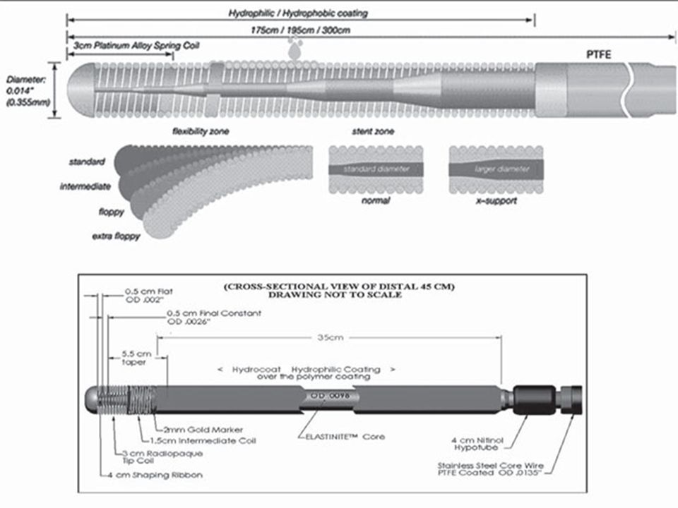
Most - calibre of inch Multi-layer constructions: Core element (usually stainless steel/or nitinol): tapers at variable points towards wire tip to impart differential stiffness along wire's length Terminal coil segment (often 30mm length; usually radio-opaque material e.g. platinum/iridium alloys): gives flexibility and allows wire tip to be shaped per operator requirements Coating: most wires – silicone/Teflon outer coating to aid easy advancement. Some coated with a hydrophilic polymer coating that becomes a gel when wet to reduce surface friction and increase wire ‘slipperiness’ Central core is the basic component of the guidewire. It contributes to the trackability, torqueability and push transmission of the interventional device. The greater is the strength of the material constituting the central core and the greater its thickness, the greater the torqueability and body support provided by it. Stainless steel contributes to more pushability, torqueability and good shape ability, but it is less flexible than newer core materials like Nitinol and also has a tendency to kink. Super-elastic alloy like Nitinol are designed for kink resistance, excellent flexibility, steering and better tip mobility 3. The tip shape with Nitinol is more durable and less likely to prolapse. However, the downside is that it may store torque without necessarily transmitting it to the tip, therefore wires with single Nitinol core have a tendency to “wind up”
: tapers at variable points towards wire tip to impart differential stiffness along wire s length. Terminal coil segment (often 30mm length; usually radio-opaque material e.g. platinum/iridium alloys): gives flexibility and allows wire tip to be shaped per operator requirements. Coating: most wires – silicone/Teflon outer coating to aid easy advancement. Some coated with a hydrophilic polymer coating that becomes a gel when wet to reduce surface friction and increase wire ‘slipperiness’ Central core is the basic component of the guidewire. It contributes to the trackability, torqueability and push transmission of the interventional device. The greater is the strength of the material constituting the central core and the greater its thickness, the greater the torqueability and body support provided by it. Stainless steel contributes to more pushability, torqueability and good shape ability, but it is less flexible than newer core materials like Nitinol and also has a tendency to kink. Super-elastic alloy like Nitinol are designed for kink resistance, excellent flexibility, steering and better tip mobility 3. The tip shape with Nitinol is more durable and less likely to prolapse. However, the downside is that it may store torque without necessarily transmitting it to the tip, therefore wires with single Nitinol core have a tendency to wind up")
26
Guide wire - construction
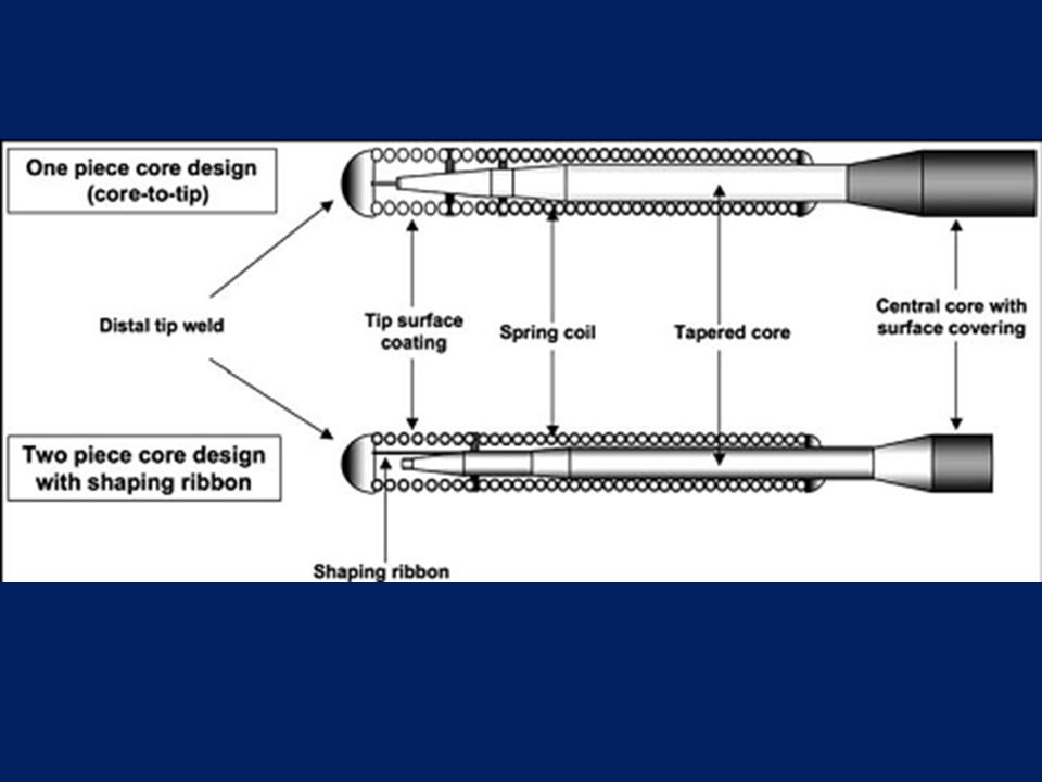
Most - calibre of inch 3 main components of guidewire design: central core outer covering flexible distal tip The wire tip may be further subdivided into spring coil & short distal tip weld Also, all guidewires have a specific surface coating applied Central core is the basic component of the guidewire. It contributes to the trackability, torqueability and push transmission of the interventional device. The greater is the strength of the material constituting the central core and the greater its thickness, the greater the torqueability and body support provided by it. Stainless steel contributes to more pushability, torqueability and good shape ability, but it is less flexible than newer core materials like Nitinol and also has a tendency to kink. Super-elastic alloy like Nitinol are designed for kink resistance, excellent flexibility, steering and better tip mobility 3. The tip shape with Nitinol is more durable and less likely to prolapse. However, the downside is that it may store torque without necessarily transmitting it to the tip, therefore wires with single Nitinol core have a tendency to “wind up”

27
Central core Longest & stiffest portion of guidewire
Tapers distally to a variable extent 2-piece core- distal part of core does not reach distal tip of wire→ shaping ribbon, extends to distal tip 1-piece core- tapered core reaches distal tip weld 2-piece →easy shaping & durable shape memory 1-piece →better force transmission to tip & greater “tactile response” for operator

29
Central core Stainless steel
superior torque characteristics, can deliver more push, provides good shapeability of tip in core-to-tip design wires more susceptible to kinking Durasteel- better tip shape retention and durability Nitinol pliable but supportive, less torquability than SS generally considered kink resistant & have a tendency to return to their original shape, making them potentially less susceptible to deformation during prolonged use Some guidewires have a composite core design, employing stainless steel for the longer proximal part within the wire shaft, and a more elastic alloy at the tapered distal part within the wire tip, such as nitinol Runthrough® NS

30
Distal tip Flexible, radio-opaque part
Consists of spring coil extending from distal untapered part of central core to distal tip weld Integrates tapered core barrel (as well as shaping ribbon in 2-piece wire) Spring coil-variable length (1-25cm)-radio-opaque section located at its terminal end Distal tip weld- short (≤2mm)compact cap forming the true distal end of the wire - to ↓ trauma while the wire is traversing vessels
 Spring coil-variable length (1-25cm)-radio-opaque section located at its terminal end. Distal tip weld- short (≤2mm)compact cap forming the true distal end of the wire - to ↓ trauma while the wire is traversing vessels.")
33
Wire Coating-hydrophilic/hydrophobic
Repels water - requires no actuation/wetting ↓friction (to ½ V/S no coating), ↑trackability Preserves tactile feel, allows easier anchorability / parking - esp CTO Silicone, Teflon
, ↑trackability. Preserves tactile feel, allows easier anchorability / parking - esp CTO. Silicone, Teflon.")
34
Attracts water - needs lubrication
Hydrophilic Attracts water - needs lubrication Thin, slippery, non-solid when dry→ becomes a gel when wet ↓friction(⅙ no coating) →glide through tortuous ↑trackability ↓Thrombogenic ↓tactile feel- ↑risk of perforation Tendency to stick to angioplasty cath Useful in negotiating tortuous lesions and in “finding microchannels” in total occlusions Lubricity is highest with hydrophilic wires, less with Silicone coating and least with PTFE or Teflon coating
 →glide through tortuous. ↑trackability. ↓Thrombogenic. ↓tactile feel- ↑risk of perforation. Tendency to stick to angioplasty cath. Useful in negotiating tortuous lesions and in finding microchannels in total occlusions. Lubricity is highest with hydrophilic wires, less with Silicone coating and least with PTFE or Teflon coating.")
35
Properties Of An Ideal Guidewire
Push transmission/steerability Torque transmission/torquability Body support/ trackability Tip support/mobility Flexibility Tip durability/elasticity Tip visibility and markers Tactile feedback Prolapse tendency

36
Push transmission/steerability: ability of a guide wire tip to be delivered to the desired position in a vessel Torque transmission: ability to transmit rotational forces from the operators hand to the tip Body support/ trackability: ability to advance balloon catheters/other devices on guidewire Tip support/mobility: Allows moving the distal tip to search for the true lumen Tip durability/elasticity: Permits shape memory retention of the distal tip throughout Tactile feedback: “feel” of the wire tip’s behavior, as perceived by the operator better appreciated with non-coated / hydrophobic coated, coil tipped wires and it ↓with hydrophilic coating

38
Shapeability and shaping memory
Shapeability - allows to modify its distal tip conformation Shaping memory - ability of tip to return back to its basal conformation after having been exposed to deformation & stress Both do not necessarily go in parallel SS core wires -easier to shape (↑memory- nitinol core) 2-piece core + shaping ribbon - easier to shape & ↑memory General rule- when negotiating a vessel with J loop, distal bend ~ D of vessel—more bend -↑wire tip prolapsing, less bend -↓ steerability
 2-piece core + shaping ribbon - easier to shape & ↑memory. General rule- when negotiating a vessel with J loop, distal bend ~ D of vessel—more bend -↑wire tip prolapsing, less bend -↓ steerability.")
39
Types Of Guidewires Depending on tip load- Balanced, Extra support, Floppy Tip load- force needed to bend a wire when exerted on a straight guide wire tip, at 1 cm from the tip Balanced – g Extra support - >0.9g Floppy - <0.5g

40
Workhorse wire: default choice - balance btw stiffness/support & flexible tip – majority lesions
Stiff wires: offer extra support for tortuous/calcified cor Floppy wires: when vessel trauma is a concern (e.g. re-crossing a dissected lesion)
")
41
Workhorse (frontline) Guidewires
• ATW/ATW Marker • Stabilizer • BMW / BMW Universal • Zinger • Cougar XT • Asahi Light / Medium • Asahi Standard • Asahi Prowater Flex • Choice Floppy • Luge • IQ • Forte Floppy • Runthrough NS • Galeo

42
Balance Middleweight Universal wire (Abbott Vascular/Guidant, Santa Clara, CA)
Quite steerable - tip is suitable for bending in a “J” configuration for distal advancement into the distal vessel bed with minimal trauma while still maintaining some torque shape retention relatively poor -any J configuration tends to become magnified over time → consequent loss in steerability moderately torquable- progression - minimal friction (light hydrophilic coating) - Dye injection may also be helpful to propagate distal advancement suitable for rapid, uncomplicated interventions low risk to cause dissections/distal perforations support - low to moderate
 - Dye injection may also be helpful to propagate distal advancement. suitable for rapid, uncomplicated interventions. low risk to cause dissections/distal perforations. support - low to moderate.")
43
Balance Middleweight wires
from the generation previous to the Universal lack light hydrophilic coating at the tip→ more steerability but requires greater effort for distal advancement more direct tactile feedback (v/s more automatic progression –Universal) Support-moderate -power steering-
 Support-moderate. -power steering-")
44
Runthrough NS® wire unique dual core design
main shaft core of SS & a distal core of nitinol alloy, which extends into a nitinol shaping ribbon distal tip is hydrophilic coated

45
Runthrough NS® wire

46
Guidewire Strategies for Approaching CTO
A) Guidewires for Approaching Micro-channels Crosswire NT Whisper / Pilot Rinato Shinobe / Shinobe Plus ChoICE PT / ChoICE PT ES PT Graphix PT2 B) Guidewires for Drilling Strategy Persuader Miracle Bros Cross-It C) Guidewires for Penetrating Strategy Cross IT Conquest Pro Liber 8 D) Guidewires for Retrograde Technique Fielder/FielderFC X -treme Whisper ChoICE PT2 Runthrough / Runthrough Hypercoat
 Guidewires for Approaching Micro-channels Crosswire NT Whisper / Pilot Rinato Shinobe / Shinobe Plus ChoICE PT / ChoICE PT ES PT Graphix PT2. B) Guidewires for Drilling Strategy. Persuader. Miracle Bros Cross-It. C) Guidewires for Penetrating Strategy. Cross IT Conquest Pro Liber 8. D) Guidewires for Retrograde Technique Fielder/FielderFC X -treme Whisper ChoICE PT2. Runthrough / Runthrough Hypercoat.")
47
CTO Start with the intermediate wire
This provides 3g of distal force and moderate support Conventional stainless steel core wire with 30mm of tip radio-opacity and in. diameter If this wire fails to cross, → Miracle series

48
Intermediate Wire (Asahi Intecc)
●Tip load g ●Tip radiopacity cm ●PTFE coating over the shaft

49
Miracle series (Asahi Intecc)
0.014 in wires - specifically designed for CTO 110mm of distal tip radio-opacity for optimal visualization Come in 4 versions of ↑ distal force: 3g, 4.5g, 6g, 12g

50
●Tip load g ●Tip radiopacity cm ●PTFE coating over the shaft

51
●Tip load g ●Tip radiopacity cm ●PTFE coating over the shaft

52
●Tip load g ●Tip radiopacity cm ●PTFE coating over the shaft

53
●Tip load g ●Tip radiopacity cm ●PTFE coating over the shaft

54
Conquest series (Asahi Intecc)
The next evolution- tapered tip Conquest wire (Confianza) Has a distal tip diameter of only in The distal tip is radio-opaque for 200mm Provides 9g of distal force Conquest Pro (Confianza Pro) Also tapered to in Provides 9g of force Hydrophilic-coated for the distal 20 cm Tip tapering is proposed to help the wire find and navigate microchannels in the occluded segment, while the hydrophilic coating of the Conquest Pro reduces the tip friction by about one-third
 Has a distal tip diameter of only in. The distal tip is radio-opaque for 200mm. Provides 9g of distal force. Conquest Pro (Confianza Pro) Also tapered to in. Provides 9g of force. Hydrophilic-coated for the distal 20 cm. Tip tapering is proposed to help the wire find and navigate microchannels in the occluded segment, while the hydrophilic coating of the Conquest Pro reduces the tip friction by about one-third.")
55
●Tip load g ●Tip radiopacity cm ●Tip outer diameter inch (0.23 mm) ●PTFE coating over the shaft

56
●Tip load g ●Tip radiopacity cm ●Tip outer diameter inch (0.23 mm) ●SLIP COAT coating over the spring coil ●PTFE coating over the shaft The distal tip is not coated to allow it to catch on the entry point of the lesions

57
●Tip load g ●Tip radiopacity cm ●Tip outer diameter inch ●SLIP COAT® coating over the spring coil ●PTFE coating over the shaft For penetration of calcification and proximal or distal thick, fibrous caps

58
●Tip load g ●Tip radiopacity cm ●Tip outer diameter inch (0.20 mm) ●SLIP COAT® coating over the spring coil ●PTFE coating over the shaft Designed for crossing complex lesions with heavy calcifications and tough fibrous tissues Finest and stiffest guidewire in the current Asahi series.

59
Fielder™ / Fielder FC™ (Asahi Intec Co.)
Special guidewire - distal coil coated with polymer sleeve & further coated with a hydrophilic coating Provides advanced slip performance & trackability for highly stenosed lesion & tortuous vessels Very good torque performance Combines both slide and torque performance Primary wire used in the retrograde technique of recanalization of CTO

60
Tip load g Tip radiopacity cm Polymer sleeve length cm SLIP COAT coating over the spring coil PTFE coating over the shaft

61
●Tip load g ●Tip radiopacity cm ●Polymer sleeve length cm ●SLIP COAT coating over the spring coil ●PTFE coating over the shaft

62
●Tip load g ●Tip radiopacity cm ●Polymer sleeve length cm ●Tip outer diameter inch(0.23 mm) ●SLIP COAT® coating over the spring coil ●PTFE coating over the shaft
 ●SLIP COAT® coating over the spring coil. ●PTFE coating over the shaft.")
65
Galeo guide wire

66
Optimum guide wire positioning
Should be placed as distally as possible in the target vessel Allows extra support when crossing with balloon/stent catheters ↓ chance of the wire becoming displaced backwards across the lesion and necessitating re-crossing Avoid vessel perforation when positioning wires with hydrophilic coatings very distally

67
Plain ‘old’ balloon angioplasty
1977- Andreas Gruentzig 1st gen balloon cath - fixed to guidewire - difficult to cross tight/tortuous lesions Initially, over-the-wire systems → new monorail systems Short guidewires Facilitates performance of PTCA by a single operator Progression in balloon technology different type, better materials, better coatings, lower-profile systems, improved delivery, ↑burst pressure, ↓compliance

68
Balloon technology

69
Construction of the balloon catheter (monorail type)
Only the distal 15–25 cm of the balloon catheter tracks over the guidewire less procedural time a single operator reduced fluoroscopy time no additional devices for the exchange

70
The catheter has a lumen through its entire length that tracks over a guidewire
Guidewire and balloon catheter move independently of each other two operators can exchange balloon catheters only with a 300 cm exchange length wire or specific products (Trapper or Magnet) in order to maintain the wire position across the lesion increased exposure to radiation because the fluoroscopy needs to be on during the placement of the balloon
 in order to maintain the wire position across the lesion. increased exposure to radiation because the fluoroscopy needs to be on during the placement of the balloon.")
71
The guidewire and balloon are on the system
The guidewire cannot be advanced independently over the Balloon Fixed system- does not allow for guidewire exchange Has the lowest profile Inability to exchange for another balloon catheter without having to recross the lesion Need to remove the whole system if the wire tip becomes damaged

72
Either an over-the-wire or a monorail design
Perfusion side holes proximal and distal to the actual balloon As the balloon is inflated, the perfusion side holes allow blood to enter the catheter through the proximal holes, flow within the inflated balloon, and exit the catheter’s distal side holes Balloon can be inflated for longer periods of time Specific situations- cor perforation & abrupt closure, that cannot be recovered by a stent Decreased trackability due to its larger diameter

73
Lumen technology Bilumen & triple-lumen designs
Currently- Coaxial shaft- innermost space is the lumen for guidewire - outer space is inflation/deflation lumen Low-profile shaft enables the kissing balloon technique using 6 Fr guiding catheters

74
Balloons Distal tip -usually tapered- allows to cross lesion less traumatically Profile of the distal tip will determine how much push is needed to get across the lesion Coating – also determinant for ability to cross A hydrophilic coating- superior in crossabilty A slippery characteristic- not suitable for in-stent restenosis- balloon will easily slip out of the lesion when inflated

75
Performance Parameters
Low entry & crossing profile- for optimum tracking & crossing Short inflation & deflation time- to avoid ischemic complications Optimum refolding characteristics- to avoid traumatization or stent damage Predictable balloon compliance- to allow precise diameter sizing High balloon-burst strength- for high-pressure dilatations Low bending stiffness- for easy tracking of curved vessels

76
Profile Largest diameter in the balloon region
To position balloon safely across tight lesions, ↓possible profiles required To cross extremely tight & long lesions, both entry & crossing profiles must be ↓ ↓profiles -to avoid luminal obstructions

77
Maximum Profile of PTCA Balloon Catheters
Distal profile (mm) Proximal profile (mm) Medtronic Sprinter 3.0/20 mm 0.85 1.00 Biotronik Elect 3.0/20 mm Guidant Voyager 3.0/20 mm 0.80 0.95 Boston Scientific Maverick23.0/20 mm Cordis AquaT3 3.0/20 mm
 Proximal profile (mm) Medtronic Sprinter 3.0/20 mm Biotronik Elect 3.0/20 mm. Guidant Voyager 3.0/20 mm Boston Scientific Maverick23.0/20 mm. Cordis AquaT3 3.0/20 mm.")
78
Inflation & Deflation Time
Inflation of a balloon within a narrowed, but not completely occluded, blood vessel results in ischemia of the dependent tissue To ↓ ischemic time - ↓ obstruction time Obstruction time =time required to transmit pressure in the hand pump to the balloon + time for balloon inflation + deflation time

79
Resistance,R- determined by viscosity, inner radius r & length l of the hypotube
Poiseuille's law So r of the tubing- major determinant of resistance Low-caliber - long inflation/deflation time→limit on ↓ catheter shaft profiles Inflation & deflation times depend on volume of balloon- not useful in balloon comparisons For balloon inflation, a clinically relevant mixture of saline & contrast agent (1:1) should be used
 should be used.")
80
Deflated balloon remains within lumen & obstructs blood flow
To minimize residual obstruction & to avoid vessel damage by “flaring” of unfolded balloon parts on retraction, the geometric refolding characteristics of balloon after deployment-important ↓cross-sectional area & smooth profile of refolded balloon - least blood-flow obstruction, avoids vessel traumatization, stent damage on withdrawal

81
Average deflation time of PTCA balloon catheters

82
Balloon Compliance Change in balloon D for a given change in balloon P
Can be either indicated as a %↑in D/bar, or listed as a table of P & corresponding balloon D- 1st useful for classification of balloons as noncompliant/semicompliant, latter is usually given by the manufacturer for each device as the compliance chart

83
High to moderate compliance balloons
Polyolefin copolymer (POC) Polyethylene (PE) [< than POC] Balloon sizing important – oversizing can easily occur Tend not only to stretch in D but also to overexpand into the areas of least resistance, i.e. prox & distal to lesion –(‘dog-boning’)- dissection observed more commonly Crossability may be superior
 Polyethylene (PE) [< than POC] Balloon sizing important – oversizing can easily occur. Tend not only to stretch in D but also to overexpand into the areas of least resistance, i.e. prox & distal to lesion –(‘dog-boning’)- dissection observed more commonly. Crossability may be superior.")
84
Nylon Thick material- compliant at ↑pressures ↑ mean burst pressures

85
Non complaint balloons
Polyethylene terephthalate (PET) thicker-walled balloon Allow work at higher pressures hard calcified lesion or post-stent dilatation
 thicker-walled balloon. Allow work at higher pressures. hard calcified lesion or post-stent dilatation.")
86
(a) A compliant balloon tends to be oversized at the edges, with less dilatation at the obstructive segment of the lesion (‘dog-boning’) (b) A noncompliant balloon gives a predictable amount of pressure at the lesion without uncontrolled radial and longitudinal growth
 A noncompliant balloon gives a predictable amount of pressure at the lesion without uncontrolled radial and longitudinal growth.")
87
D Compliance of High-pressure PTCA Balloons
Diameter compliance (%/bar) Medtronic Sprinter 3.0/20 mm 9.92 Biotronik Elect 3.0/20 mm 5.50 Guidant Voyager 3.0/20 mm 8.99 Boston Scientific Maverick23.0/20 mm 9.88 Cordis AquaT3 3.0/20 mm 5.88
 Medtronic Sprinter 3.0/20 mm Biotronik Elect 3.0/20 mm Guidant Voyager 3.0/20 mm Boston Scientific Maverick23.0/20 mm Cordis AquaT3 3.0/20 mm")
88
Balloon Burst Strength
The radial & axial stresses (σrad, σax) depend on balloon pressure p, balloon diameter d, & thickness s of balloon wall Balloon will burst if stresses exceed rupture stress of the material Stress- linear correlation with P & D, and inverse relationship to balloon thickness Given the same material, a larger balloon diameter & thin balloon material →↓burst P Also within the balloon axial stress is ½ as big as radial stress
 depend on balloon pressure p, balloon diameter d, & thickness s of balloon wall. Balloon will burst if stresses exceed rupture stress of the material. Stress- linear correlation with P & D, and inverse relationship to balloon thickness. Given the same material, a larger balloon diameter & thin balloon material →↓burst P. Also within the balloon axial stress is ½ as big as radial stress.")
89
RBP→ the maximum recommended P for safe use - 99
RBP→ the maximum recommended P for safe use % of the tested balloons will not fail at RBP with 95% confidence Nominal P→ the P at which balloon will have expanded to the manufacturer-specified size e.g. a 2.5mm D balloon expanded to nominal P should have an external diameter of 2.5mm

90
The dilating force Pressure (hydrostatic force) put in the balloon
Tension determined by balloon diameter, balloon material/compliancy, and vector force (the amount of constriction) Therefore, balloon size and balloon compliance are the major determinants for successful mechanical dilatation
 Therefore, balloon size and balloon compliance are the major determinants for successful mechanical dilatation.")
91
In IVUS , dissection is observed in up to 60–70% of dilated segments
Dissection may be necessary for optimal results after POBA

92
Long lesions(>20mm)- may be treated with long balloon to avoid dissection at edges
Soft lesions(recent)-↑lipid conc-↓inflation P Calcified lesions(cholesterol, conn tissue,& muscle cells)-↑dissection/perforation chance -NC balloon-allows ↑inflation P to crack lesion Calcified lesions & post stent dilatation- ↑rated burst P & shorter balloons better Size of balloon- based on ref vessel D - balloon/artery ratio of ~ 1.1 currently recom
-↑lipid conc-↓inflation P. Calcified lesions(cholesterol, conn tissue,& muscle cells)-↑dissection/perforation chance -NC balloon-allows ↑inflation P to crack lesion. Calcified lesions & post stent dilatation- ↑rated burst P & shorter balloons better. Size of balloon- based on ref vessel D - balloon/artery ratio of ~ 1.1 currently recom.")
93
Trackability Crossability Pushability
ability of a system to be advanced to a target lesion affected by several technical parameters such as friction, bending stiffness etc Crossability ability to pass stenoses Pushability load transfer from interventionist‘s end to the distal tip of catheter High load transfer allows finer & more direct tactile control of the instrumentation Even small obstructions that cause only a minor ↑ in reaction forces at the catheter tip can be felt by the operator, allowing him to tune and finely adjust the pushing force to overcome the obstacle while utilizing the least injurious maneuver

94
Crossing Difficult Lesions
Following techniques use of stronger back-up catheters deep insertion of guide adding vibration Pushing balloon while pulling guidewire use of a stiff guidewire Buddy wire technique

95
Elect: Fast-exchange Balloon Catheter
Low shaft profile- compatible with smaller guide (5F compatibility for all balloon sizes) Hydrophilic coating improves gliding Soft Tapered Tip(Laser-rounded)-↑safety & crossability Embedded Platinum-Iridium Markers- optimized visibility, ↓crossing profile
 Hydrophilic coating improves gliding. Soft Tapered Tip(Laser-rounded)-↑safety & crossability. Embedded Platinum-Iridium Markers- optimized visibility, ↓crossing profile.")
96
Elect: Fast-exchange Balloon Catheter
Lesion entry profile 0.017" Shaft diameter Proximal: 2.0F; Distal: 2.4F (Ø mm) , 2.6F (Ø mm), 2.7F (Ø 3.75–4.0 mm) Recommended guide catheter 5F (min. I.D ") Nominal Pressure 7 bar Rated burst pressure (RBP) 18 bar (Ø 1.25mm), 16 bar (Ø 1.5- 2.25 mm), 14 bar (Ø mm)
 , 2.6F (Ø mm), 2.7F. (Ø 3.75–4.0 mm) Recommended guide catheter. 5F (min. I.D ) Nominal Pressure. 7 bar. Rated burst pressure (RBP) 18 bar (Ø 1.25mm), 16 bar (Ø mm), 14 bar (Ø mm)")
97
Pleon Superb pushability & crossability- esp suitable for reaching difficult target lesions laser-rounded soft tip hydrophilic coating

98
Jocath Mercury PTCA Catheter

99
Jocath Mercury PTCA Catheter
Balloon Compliance: Semi-compliant Shaft Diameter: 2.0F proximal 2.7F distal Shaft length: cm Lesion Entry Profile: 0.017" Nominal Pressure: 8 bar Rated Burst Pressure: 16 bar Average Burst Pressure: 22 bar Coating: HYDREX Coating System Min. Guiding Catheter: 5F (0.058")
")
100
NC Mercury PTCA Catheter
Maximized wall apposition due to NC balloon behavior Minimal balloon overhang- to limit vessel injury during high P dilatation Minimal tip flaring Fast deflation time Efficient access- low entry profile

101
Coronary stents

102
Ulrich Sigwart & Joel Puel in 1987 implanted the first stent in a human coronary artery in Toulouse, France

103
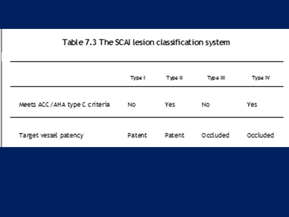
TYPES OF STENTS Metal composition Open v/s closed cell designs
Thickness of struts Eluting drugs Stent design may be specific -small (<2.5 mm diameter) vessels / bifurcation lesions
 vessels / bifurcation lesions.")
104
Metal composition Cobalt-chromium - more deliverable for challenging lesions Stainless steel designs - greater radial strength for bulky lesions or those involving more muscular aorto-ostial locations Co-Cr - stronger & more radiopaque than SS → thinner struts, lower profiles (<0.40”), better flexibility & similar radial strength
, better flexibility & similar radial strength.")
105
Stent structure Slotted tube stents Modular stents
Multicellular stents Modular-multicellular stent (hybrid stents)
")
106
Slotted tube stents Slotted tube stents are made just by cutting longitudinal slashes in tubes

107
Modular stents Consist of several crown-shaped modules, which may be manufactured from metal wires that are punctually connected to form a tube ie, based on repeating identically designed units, again laser-cut, linked together by welded struts An ‘open-cell’ design Highly flexible Offer better side-branch access Boston Scientific Express stent

108
Open-cell/modular stent design
Multiple repeating modules are linked at certain points of the design, giving flexibility but less metal : artery coverage Medtronic DriverTM stent

109
The Palmaz-Schatz stent
Based on repeating modules

110
Multicellular stents Completely closed cell design Less flexible
Uniform vessel wall coverage preventing tissue prolapse Guidant Multi-Link

111
Closed-cell stent design
Modern closed-cell stents have relatively large cells Boston LiberteTM stent

112
Modular-multicellular stent
Also called hybrid stents Try to combine the advantages of multicellular and modular stents Lekton Motion, Pro Kinetic

113
Cell design Closed cell (in which each ring is interconnected)
more support less flexible Open cell improves flexibility improves sidebranch access reduce radial support

114
Cell - small but regularly repetitive structure of a stent
Strut- single element that forms larger structural entities such as cells, rings, or crowns Cell - small but regularly repetitive structure of a stent Open cells have a more complicated structure than closed cells Cells represent the elementary geometrical figure of the stent- will deform during stent expansion Rings and crowns- comprise a cluster of cells forming a higher-order geometrical pattern of the stent, which may form complete stent segments usually coupled by longitudinal bridges or links

115
Strut thickness Thinner struts - ↓ vessel injury
Strut thickness <100 microns - thin strut stents

116
Stent coating The eluted drug is linked by a degradable/permanent polymer coating only a few micrometers in thickness not expected to change mechanical strength may affect surface friction

117
Provides local delivery of a drug
Methods for the storage and controlled release Nondegradable or biodegradable polymer Cavities on the stent struts- drug depots Small amounts of drugs applied directly to stent surface Nondegradable polymers- polyurethane, silicone, polyorganophosphazene, polymethacrylate, poly(ethylene terephthalate), & phosphorylcholine Biodegradable polymer- poly(l-lactide), poly(3-hydroxybutyrate), polycaprolactone, polyorthoester, fibrin
, & phosphorylcholine. Biodegradable polymer- poly(l-lactide), poly(3-hydroxybutyrate), polycaprolactone, polyorthoester, fibrin.")
118
DES- mechanism of benefit
Late lumen loss and restenosis after nonstent interv -combination of acute recoil, negative remodeling (arterial contraction), and local neointimal hyperplasia Late lumen loss after stenting - solely to in-stent neointimal hyperplasia The restenosis benefit of DES compared to BMS results from inhibition of in-stent neointimal hyperplasia , which is reflected as a lesser degree of late in-stent lumen loss at 6-9/12 (0.2 to 0.4 versus 0.9 to 1.0 mm with BMS) -Neointimal suppression is still sustained at 2years
, and local neointimal hyperplasia. Late lumen loss after stenting - solely to in-stent neointimal hyperplasia. The restenosis benefit of DES compared to BMS results from inhibition of in-stent neointimal hyperplasia , which is reflected as a lesser degree of late in-stent lumen loss at 6-9/12 (0.2 to 0.4 versus 0.9 to 1.0 mm with BMS) -Neointimal suppression is still sustained at 2years.")
119
In the Ontario registry the benefit was limited to those patients with two or three risk factors for restenosis (diabetes, vessels <3 mm in diameter, and lesions ≥ 20 mm in length) In the Swedish Coronary Angiography and Angioplasty Registry (SCAAR), the benefit with DES compared with BMS was most apparent when any one of these high risk features was present
, the benefit with DES compared with BMS was most apparent when any one of these high risk features was present.")
120
Sirolimus aka Rapamycin- immunosuppressant drug - macrolide
First discovered from Streptomyces hygroscopicus in Easter island soil sample— island aka "Rapa Nui", hence named Originally developed as an anti-fungal agent Sirolimus is lipophilic - crosses cell membranes – binds FK binding protein-12 (FKBP-12)→an active complex Sirolimus:FKBP-12 complex→binds & inhibits mammalian Target Of Rapamycin (TOR) Inhibition of this enzyme→↓cytokine-dependent cellular proliferation at G1 to S phase of cell cycle The mechanism of inhibition is cytostatic rather than cytotoxic as the affected cells remain viable
→an active complex. Sirolimus:FKBP-12 complex→binds & inhibits mammalian Target Of Rapamycin (TOR) Inhibition of this enzyme→↓cytokine-dependent cellular proliferation at G1 to S phase of cell cycle. The mechanism of inhibition is cytostatic rather than cytotoxic as the affected cells remain viable.")
121
Paclitaxel Mitotic inhibitor isolated it from bark of the Pacific yew tree, Taxus brevifolia, hence named taxol Stabilizes microtubules→ interferes with the N breakdown of microtubules during cell division→prevents DNA synth Paclitaxel-inhibited cells remain at the G0/G1 and G2/M interfaces of the cell cycle Cells exposed to paclitaxel undergo apoptosis/cell death- cytotoxic

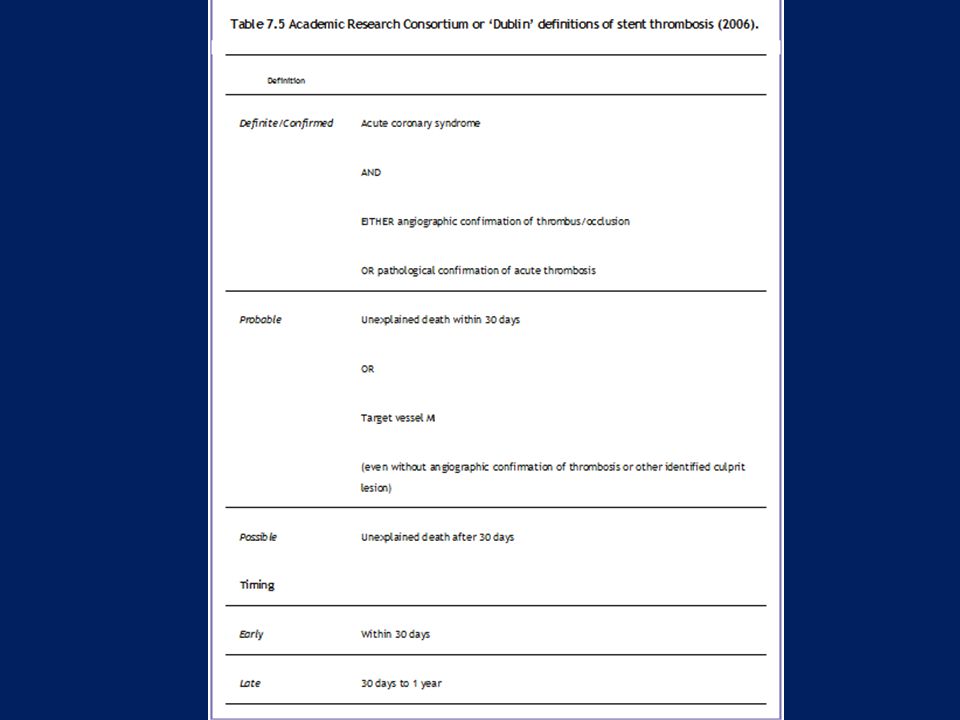
124
Sirolimus is a cytostatic inhibitor of SMC and EC proliferation via specific intracellular protein interactions with FKBP-12, subsequently inhibiting TOR, p70 S6K, and cyclin-CDK complexes. Different intracellular signaling pathways activate the migration of ECs and SMCs. The migration of ECs utilizes a Ras-p42/p44 MAP-kinase signaling pathway, which is not inhibited by sirolimus. Paclitaxel is a cytotoxic inhibitor of SMCs and ECs via non-specific inhibition of microtubule disassembly. The models in Figure 3 demonstrate how differential effects of these two drugs on EC may delay the process of re-endothelialization during stent-induced vessel injury and endothelial denudation.

125
Everolimus A rapamycin analogue
Novel macrolide with potent immunosuppressive & antiproliferative effect Arrests cell cycle at the G1 to S phase

126
Biodegradable stents Intended to support a vessel for just as long as is necessary to complete the healing process and to then disappear after a specified time period Complications resulting from long-term intravascular presence of a FB- thrombogenicity, permanent mechanical irritation, prevention of positive remodeling, are eliminated Poly(L-lactic acid) (PLLA), poly(D-lactic acid) (PDLA), poly(e-caprolactone) (PCL), poly(glycolic acid) (PGA)
 (PLLA), poly(D-lactic acid) (PDLA), poly(e-caprolactone) (PCL), poly(glycolic acid) (PGA)")
127
Scanning electron micrograph of a PLLA stent prototype

128
NexgenTM Cobalt Chromium Coronary Stent System
Hybrid cell design Ultra-low strut thickness of 65µm The balloon overhang is 0.3mm ensuring that balloon related injury is marginalized

129
Stent Material : Cobalt Chromium L605 Strut Thickness : 65 µm (0.065mm or ") Stent Diameters (mm) : 2.50, 2.75, 3.00, 3.50, 4.00, 4.50 Stent Lenghts (mm) : 8, 13, 16, 19, 24, 29, 32, 37, 40 Mean Foreshortening : 0.29%
 : 8, 13, 16, 19, 24, 29, 32, 37, 40. Mean Foreshortening. : 0.29%")
130
genX™CrCo coronary stent
Stent material L605 Co-Cr alloy Design 10 Crown , variable – geometry Strut thickness 65 micro meters Strut Width Large 70 micro meters Small 60 micro meters Guiding catheter 5 Fr compatible Crossing profile < 1 mm

131
genX™ coronary stent Stent material SS316L Stainless Steel Design
10 Crown , variable – geometry Strut thickness 105 micro meters Strut Width Large 85 micro meters Small 75 micro meters Guiding catheter 5 Fr compatible Crossing profile < 1 mm

132
Lekton Motion Combines cell pattern & Z-shaped connections
Strut thickness of 90µm Ultra low profile (<1.00mm) permits excellent tracking & crossing Also available in 2 versions: Petite (vessels <2.5mm) & Mega (vessels >4mm)
 permits excellent tracking & crossing. Also available in 2 versions: Petite (vessels <2.5mm) & Mega (vessels >4mm)")
133
Petite 80 µm struts Small vessel design with lowest crossing profile Shaft with Enhanced Force Transmission technology permits exellent positionning in distal anatomy Mega Compatible with 5F guide catheters in all sizes Special design for optimal flexibility and support of large vessels (>4mm) Maximum expansion: 5.5 mm
 Maximum expansion: 5.5 mm.")
134
PRO-Kinetic Cobalt Chromium Stents Struts- 60 µm (0.0024“)
3 Different Design Specific designs for small, medium and large arteries Low Profile Low profile (0.95 mm) permits easy track & cross Double Enhanced Force Transmission Shaft (EFT) ↑shaft flexibility & kink resistance Hydroglide coating ↓Shaft Profile- all sizes compatible with 5F space stents
 permits easy track & cross. Double Enhanced Force Transmission Shaft (EFT) ↑shaft flexibility & kink resistance. Hydroglide coating. ↓Shaft Profile- all sizes compatible with 5F space stents.")
135
Angstrom Material- 316LVM Stainless Steel Non-Ferromagnetic
Strut Width 0.09 mm Closed-cell design Profile before Delivery < 1mm

136
genXsync Uniform sinus design
Alternate ‘S’ link offers excellent flexibility Biodegradable polymer in single layer→initial burst of sirolimus followed by sustained elution up to 40 days Polymer degrades by hydrolysis & enzymatic →excreted in form of CO2 & H20 PTFE hypotubing shaft- improved pushability Super thin alloy (65µm) with ultra thin coating (3µm) Low crossing profile drug eluting stent (< 0.85 mm)
 with ultra thin coating (3µm) Low crossing profile drug eluting stent (< 0.85 mm)")
137
Uniform sinusoidal cell design
Stent material L 605 Chromium Cobalt Design Uniform sinusoidal cell design Coating Bioresorbable and biodegradable polymers Drug Sirolimus Strut thickness 65 µm Strut width 85 µm Nominal foreshortening Nearly zero Recoil < 4.0% Guiding Catheter 5 Fr Compatible Crossing Profile < 0.85 mm

138
CYPHER® Stent Stent Geometry Closed-cell FLEXSEGMENT™ Technology
Material 316L Stainless Steel Strut Thickness .0055" Crimped Profile .044" Available Sizes Diameters: 2.25, 2.50, 2.75, 3.00, 3.50 mm Lengths: 8, 13, 18,23, 28, 33 mm Drug Delivered Sirolimus Mechanism of Action Inhibits m TOR to block growth factor induce proliferation Cytostatic Drug Delivery Vehicle Controlled-release, nonresorbable, elastomeric polymer coating Drug Release Kinetics 80% of sirolimus released in 30 days Approval Status Approved by FDA

139
Biomime

140
Angstrom lll Closed-cell design Stainless steel Paclitaxel eluting

141
XIENCE V 0.0032” strut thickness
Clinically proven MULTI-LINK VISION CoCr stent

142
Endeavor Sprint Zotarolimus-Eluting Coronary Stent System

143
Attempts to ↓ the amount of balloon protrusion outside the stent →↓vessel trauma in adjacent cor segs A perfect match not yet achieved Diffuse disease- Minimal balloon overhand Significant vessel tapering- Minimal balloon overhand

144
A = plaque compression B = superficial tear/fissure (intimal) C = deeper sub-intimal tear D = subintimal tear with localized dissection E = deep subintimal tear with extensive dissection reaching media F = circular sub-intimal dissection In eccentric lesions, stretching of vessel wall (without plaque) and sub-medial dissection can occur
 and sub-medial dissection can occur.")
145
Vessel size In the beginning - elective stent deployment limited to large cor (≥ 3 mm) STRESS trial →elective stenting provided superior angiographic & clinical outcomes in vessels <3 mm (stented using 3 mm stents)
")
147
Optimal stenting Deployment with only minimal residual luminal stenosis -↓risk of both ST & ISR Suboptimal luminal dilation inadequate balloon expansion (related in part to plaque characteristics) & elastic recoil ( asso with stent design & resistance)
 & elastic recoil ( asso with stent design & resistance)")
148
STARS→ 265 (13.5%) of 1,965 pts enrolled met prespecified criteria for suboptimal stenting
(defined as residual stenosis >10 percent, evidence of stent thrombosis, dissection or abrupt closure, absence of TIMI III flow, or need for three or more stents) Acute and nine-month clinical outcomes after "suboptimal" coronary stenting: results from the STent Anti-thrombotic Regimen Study (STARS) registry J Am Coll Cardiol 1999 Sep;34(3):
 Acute and nine-month clinical outcomes after suboptimal coronary stenting: results from the STent Anti-thrombotic Regimen Study (STARS) registry J Am Coll Cardiol 1999 Sep;34(3):")
149
↑periprocedural NSTEMI (8.7 v/s 4.2 %)
Suboptimal stenting ↑periprocedural NSTEMI (8.7 v/s 4.2 %) ↑overall 30 day mortality (1.1 v/s 0.06 %) ↑clinical restenosis (27 v/s 16 %) ↑ 9/12 MACE(death,MI,TVR), esp due to ↑NSTEMI(9 v/s 4.6 %) & TVR(15.5 v/s 10.2 %) Acute and nine-month clinical outcomes after "suboptimal" coronary stenting: results from the STent Anti-thrombotic Regimen Study (STARS) registry J Am Coll Cardiol 1999 Sep;34(3):
 ↑overall 30 day mortality (1.1 v/s 0.06 %) ↑clinical restenosis (27 v/s 16 %) ↑ 9/12 MACE(death,MI,TVR), esp due to ↑NSTEMI(9 v/s 4.6 %) & TVR(15.5 v/s 10.2 %) Acute and nine-month clinical outcomes after suboptimal coronary stenting: results from the STent Anti-thrombotic Regimen Study (STARS) registry J Am Coll Cardiol 1999 Sep;34(3):")
150
Role of predilation classic approach
Predilation→ stent deployment→ high-P postdilation ↑procedure time ↑radiation exposure ↑contrast use ↑cost

151
Tight/heavily calcified lesions, esp in tortuous vessels→ ↑risk of stent dislodgement from delivery balloon & potential embolization of the stent Predilatation – also preferred when precise positioning of distal end of the stent is mandatory- potentially poor visualization of the vessel distal to the stent may occur, particularly in critical stenoses

152
Direct stenting Theoretically less traumatic to vessel wall
May be esp beneficial in the presence of thrombus/when treating degenerated SVG Direct stenting →↓ procedure time, ↓contrast Prox anat landmark- side branch/Ca spot, to guide stent positioning - helpful during direct stenting Use of extra support guidewires & optimal cath support recommended

153
Settings in which direct stenting might be considered
Vessel ≥ 2.5 mm Absence of severe cor Ca Absence of signi angulation (>45º) Absence of occlusions & bifurcations
 Absence of occlusions & bifurcations.")
154
Direct stenting Potential Advantages Potential Drawbacks
Avoidance of multiple exchanges Failure to track Less trauma Failure of precise positioning, incomplete deployment Lower rate of “no-reflow” Stent damage or loss Shorter procedural time Incomplete apposition Lower procedural costs Traumatization of the target vessel

155
(BET, SWIBAP, PREDICT, CONVERTIBLE, and TRENDS)
Major outcomes – similar (proc success, adv events, MACE) Direct stenting for CSA- asso with ↓periprocedural microcirculatory injury v/s pre-dilation -50 pts - J Am Coll Cardiol Mar 18;51(11):1060-5
 Direct stenting for CSA- asso with ↓periprocedural microcirculatory injury v/s pre-dilation -50 pts - J Am Coll Cardiol Mar 18;51(11):")
156
STEMI undergoing PPCI → ↓embolization of plaque constituents, ↓no-reflow →↑myo perfusion & salvage
A randomized comparison DS v/s Conv-( J Am Coll Cardiol 2002 Jan 2;39(1):15-21) pts- 102/104- Composite end point of slow & no-reflow/embolization- (DS-11.7% vs. 26.9%, p = 0.01) No ST resolution in 20.2% (DS) vs. 38.1%, p = 0.01 STEMI-Angio & clinical outcomes asso with direct v/s conv in pts treated with lytic therapy –( Am J Cardiol 2005 Feb 1;95(3):383-6) - Direct stenting -↓death, MI, or CCF during hosp & at 30 days -independently asso with ↑ in-hospital outcomes
:15-21) pts- 102/104- Composite end point of slow & no-reflow/embolization- (DS-11.7% vs. 26.9%, p = 0.01) No ST resolution in 20.2% (DS) vs. 38.1%, p = STEMI-Angio & clinical outcomes asso with direct v/s conv in pts treated with lytic therapy –( Am J Cardiol 2005 Feb 1;95(3):383-6) - Direct stenting -↓death, MI, or CCF during hosp & at 30 days -independently asso with ↑ in-hospital outcomes.")
157
Spot stenting Using the shortest possible stent only in the particular segments of a lesion - proposed by Colombo & colleagues Attractive strategy, given the poor outcomes of long lesions treated with very long (>32 mm) stents Clinical events & TLR ↓in spot stenting gp than in conven (22% v/s 38% & 19% v/s 34%, resp)- Colombo A, De Gregorio J, Moussa I, et al: J Am Coll Cardiol 2001; 38:1427–33. Use of long stents to treat vessels >3.5 mm in diameter provides acceptable restenosis rates, whereas minimizing stent length is important in small vessels
 stents. Clinical events & TLR ↓in spot stenting gp than in conven (22% v/s 38% & 19% v/s 34%, resp)- Colombo A, De Gregorio J, Moussa I, et al: J Am Coll Cardiol 2001; 38:1427–33. Use of long stents to treat vessels >3.5 mm in diameter provides acceptable restenosis rates, whereas minimizing stent length is important in small vessels.")
158
Role of high pressure balloon dilation
High (16 to 20 atm) & low (8 to 10 atm) Stents usually deployed with a high P technique utilizing ≥ 12 to 16 atm Lower P deployment (8 to 14 atm) -signi vessel tapering/when prox edge injury is a concern, as is the case with use of drug-eluting stents Most cases- high-pressure postdilation with an appropriately sized NC balloon at 12 to 16 atm to achieve full stent expansion
 & low (8 to 10 atm) Stents usually deployed with a high P technique utilizing ≥ 12 to 16 atm. Lower P deployment (8 to 14 atm) -signi vessel tapering/when prox edge injury is a concern, as is the case with use of drug-eluting stents. Most cases- high-pressure postdilation with an appropriately sized NC balloon at 12 to 16 atm to achieve full stent expansion.")
159
Intracoronary stenting without anticoagulation accomplished with intravascular ultrasound guidance- Circulation 1995 Mar 15;91(6): With an inflation pressure of /- 3.0 atm and a balloon-to-vessel ratio of /- 0.19, optimal stent expansion was achieved in 321 of the 334 patients (96%) who underwent intravascular ultrasound evaluation The use of high-pressure final balloon dilatations and confirmation of adequate stent expansion by intravascular ultrasound provide assurance that anticoagulation therapy can be safely omitted. This technique significantly reduces hospital time and vascular complications and has a low stent thrombosis rate
 who underwent intravascular ultrasound evaluation. The use of high-pressure final balloon dilatations and confirmation of adequate stent expansion by intravascular ultrasound provide assurance that anticoagulation therapy can be safely omitted. This technique significantly reduces hospital time and vascular complications and has a low stent thrombosis rate.")
160
Influence of balloon pressure during stent placement in native coronary arteries on early and late angiographic and clinical outcome: A randomized evaluation of high-pressure inflation- Circulation 1999 Aug 31;100(9):918-23 The systematic use of high-balloon-pressure inflation (15 to 20 atm) during coronary stent placement is not associated with any significant influence on the 1-year outcome of patients undergoing this intervention
 during coronary stent placement is not associated with any significant influence on the 1-year outcome of patients undergoing this intervention.")
161
Optimal residual stenosis
ACC/AHA guidelines recommend an optimal residual stenosis (RS) after PCI of less than 20 percent 748 pts rescue or adjunctive PCI after thrombolytic therapy and had an RS less than 20% Patients with less than 0 percent RS were compared to those with a 0 to 20 percent RS patients with 0 percent RS were less likely to achieve normal myocardial perfusion (as manifested by a significantly higher rate of abnormal myocardial perfusion grades) and the presence of 0 percent RS was independently associated with a higher rate of in-hospital and 30 day mortality. Possible mechanisms include more downstream embolization of atheromatous debris due to greater disruption of plaque and thrombus, increased vessel wall injury, and coronary vasoconstriction due to stimulation of arterial stretch receptors Gibson CM; Kirtane A et al. J Am Coll Cardiol 2005 Feb 1;45(3):357-62
 after PCI of less than 20 percent. 748 pts rescue or adjunctive PCI after thrombolytic therapy and had an RS less than 20% Patients with less than 0 percent RS were compared to those with a 0 to 20 percent RS. patients with 0 percent RS were less likely to achieve normal myocardial perfusion (as manifested by a significantly higher rate of abnormal myocardial perfusion grades) and the presence of 0 percent RS was independently associated with a higher rate of in-hospital and 30 day mortality. Possible mechanisms include more downstream embolization of atheromatous debris due to greater disruption of plaque and thrombus, increased vessel wall injury, and coronary vasoconstriction due to stimulation of arterial stretch receptors. Gibson CM; Kirtane A et al. J Am Coll Cardiol 2005 Feb 1;45(3):")
162
Type A: small radiolucent area within the lumen of the vessel
Classification of dissections proposed by National Heart, Lung, and Blood Institute Bypass Angioplasty Revascularization Investigation (BARI). Type A: small radiolucent area within the lumen of the vessel Type B: linear, nonpersisting extravasations of contrast P.70 Type C: extraluminal, persisting extravasations of contrast Type D: spiral-shaped filling defect with delayed but complete distal flow Type E: persistent filling defect with delayed antegrade flow and incomplete distal flow Type F: filling defect with total occlusion
. Type A: small radiolucent area within the lumen of the vessel. Type B: linear, nonpersisting extravasations of contrast. P.70. Type C: extraluminal, persisting extravasations of contrast. Type D: spiral-shaped filling defect with delayed but complete distal flow. Type E: persistent filling defect with delayed antegrade flow and incomplete distal flow. Type F: filling defect with total occlusion.")
163
The classification of coronary dissections based on IVUS differentiates between the following types:
Intimal: limited to the atheroma and/or intima Medial: extending into the media Adventitial: extending through the external elastic membrane (EEM) Intramural hematoma: “an accumulation of blood within the medial space, displacing the internal elastic membrane inward and EEM outward. Entry and/or exit points may or may not be observed†Intrastent: “separation of neointimal hyperplasia from stent struts, usually seen only after treatment of in-stent restenosisâ
 Intramural hematoma: “an accumulation of blood within the medial space, displacing the internal elastic membrane inward and EEM outward. Entry and/or exit points may or may not be observed†Intrastent: “separation of neointimal hyperplasia from stent struts, usually seen only after treatment of in-stent restenosisâ.")
165
Hospital discharge Patients undergoing elective stenting are generally discharged within 24 hours after stent implantation following overnight observation and monitoring

166
EPOS trial 800 pts elective PCI
Same-day discharge (after 4hrs of bed rest & 4hrs of ambulation) V/S overnight stay Femoral approach with 5F or 6F guiding catheters, pretreatment with 100mg of asa, single 5000 IU hep, 300mg clopi post procedure in pts who were stented 80%- eligible for same-day discharge in both gps Suitability criteria for early discharge -freedom from sympts & absence of ECG changes & puncture site abn Same-day discharge after elective PCI is feasible and safe in the majority (80%) of patients selected for day-case PCI. Same-day discharge does not lead to additional complications compared with overnight stay Limitations- postprocedural rather than preprocedural clopi; no use of bivalirudin or glycoprotein IIb/IIIa inhibitors; small catheter sizes and elective admission for PCI rather than PCI directly following angiography Heyde GS; Koch KT et al. Circulation May 1;115(17):
 V/S overnight stay. Femoral approach with 5F or 6F guiding catheters, pretreatment with 100mg of asa, single 5000 IU hep, 300mg clopi post procedure in pts who were stented. 80%- eligible for same-day discharge in both gps. Suitability criteria for early discharge -freedom from sympts & absence of ECG changes & puncture site abn. Same-day discharge after elective PCI is feasible and safe in the majority (80%) of patients selected for day-case PCI. Same-day discharge does not lead to additional complications compared with overnight stay. Limitations- postprocedural rather than preprocedural clopi; no use of bivalirudin or glycoprotein IIb/IIIa inhibitors; small catheter sizes and elective admission for PCI rather than PCI directly following angiography. Heyde GS; Koch KT et al. Circulation May 1;115(17):")
167
SAFETY OF MRI Based upon available evidence, it appears to be safe to perform an MRI at any time after placement of coronary artery stents of any type

168
Thanks…

Similar presentations


, FSCAI>")


