Download presentation
Presentation is loading. Please wait.

1
DLL Overview The concerns at the Data Link Layer include:
What services should be provided to upper layers? Framing, Error Control. Flow Control.

2
DLL Design Overview The goal of the data link layer is to provide reliable, efficient communication between adjacent machines connected by a single communication channel. Specifically: 1. Group the physical layer bit stream into units called frames. Note that frames are nothing more than "packets" or "messages". By convention, we'll use the term "frames" when discussing DLL packets. 2. Sender checksums the frame and transmits checksum together with data. The checksum allows the receiver to determine when a frame has been damaged in transmit. 3. Receiver re-computes the checksum and compares it with the received value. If they differ, an error has occurred and the frame is discarded. 4. Perhaps return a positive or negative acknowledgment to the sender. A positive acknowledgment indicate the frame was received without errors, while a negative acknowledgment indicates the opposite. 5. Flow control. Prevent a fast sender from overwhelming a slower receiver. For example, a supercomputer can easily generate data faster than a PC can consume it. 6. In general, provide service to the network layer. The network layer wants to be able to send packets to its neighbors without worrying about the details of getting it there in one piece. At least, the above is what the OSI reference model suggests. As we will see later, not everyone agrees that the data link layer should perform all these tasks.

3
DLL Design Issues Services provided to the N/W layer Framing
Error Control Flow Control

4
1.SERVICES PROVIDED TO THE NETWORK LAYER
The main fn of the DLL is to provide services to the n/w layer The principal service is transferring data from the n/w layer of 1 m/c to the n/w layer of another m/c On the src m/c there is an entity(process) in the n/w layer that hands some bits to the DLL for txn to the destn m/c,so they can b handed over to the n/w layer there. Virtual Actual
 in the n/w layer that hands some bits to the DLL for txn to the destn m/c,so they can b handed over to the n/w layer there. Virtual. Actual.")
5
2 DLL processes communicating using DL protocol
SERVICES PROVIDED TO THE NETWORK LAYER 2 DLL processes communicating using DL protocol 3 services commonly provided are: 1.UnAcknowledged Connection less service 2.Acknowledged connection less service 3.Acknowledged connection-oriented service

6
SERVICES PROVIDED TO THE NETWORK LAYER
DLL Design Unacknowledged Connection-less Service -- Best Effort: The receiver does not return acknowledgments to the sender, so the sender has no way of knowing if a frame has been successfully delivered. No connection is established beforehand and released afterward. If a frame is lost ,no attempt is made to recover it in the DLL. This service is appropriate when The error rate is very low ,so recovery is left to higher layers For real-time traffic such as speech, in which late data is worse than bad. Most LANs use unacknowledged connection less service in the DLL

7
SERVICES PROVIDED TO THE NETWORK LAYER
DLL Design SERVICES PROVIDED TO THE NETWORK LAYER Acknowledged Connection-less Service -- Acknowledged Delivery: The receiver returns an acknowledgment frame to the sender indicating that a data frame was properly received. Still no connection. But each frame sent is individually acknowledged. If it has not arrived within a specified time interval, it can b sent again. It is useful for unreliable channels such as wireless s/ms.

8
SERVICES PROVIDED TO THE NETWORK LAYER
DLL Design SERVICES PROVIDED TO THE NETWORK LAYER Acknowledged Connection-Oriented Service -- Reliable Delivery: This is the most sophisticated service provided by DLL to N/WL. A connection is established first Each frame sent over the connection is numbered. DLL guarantees that each frame sent is rxed, It also guarantees that each frames rxed exactly once and that all frames r rxed in the right order. Frames are delivered to the receiver reliably and in the same order as generated by the sender.

9
SERVICES PROVIDED TO THE NETWORK LAYER
Placement of the data link protocol Eg:A WAN subnet consisting of routers connected by point-to-point leased telephone lines. When a frame arrives at a router, the h/w verifies the checksum and passes the frame to the DLL s/w. This checks to see if this is the frame expected ,and if packet contained in the payload field to the routing s/w. The routing s/w chooses the appropriate outgoing line and passes the packet back down to the DLL s/w which the transmits it.

10
SERVICES PROVIDED TO THE NETWORK LAYER
DLL Design Delivery Mechanisms: Connection-Less Connection Oriented Acknowledged UN-Acknowledged “Best Effort” Better Quality Reliable Delivery

11
2.FRAMING DLL Design To provide service to the n/w layer the DLL must use the service given by the Phy.Layer. Function of phy.layer is accept a raw bit stream and attempt to deliver it to the destn. This bit stream is not guaranteed to b error free. The no. of bits rxed may b less or more than that of txed.and they hav different values. So DLL hav to take care of error detection and correction. For this purpose , The DLL translates the physical layer's raw bit stream into discrete units (messages) called frames and compute the check sum for each frame. When a frame arrives at the destn the checksum is recomputed. If the newly computed checksum is diffrnt from the one contained in the frame, the DLL knows that an error has occurred an takes steps to deal with it.
 called frames and compute the check sum for each frame. When a frame arrives at the destn the checksum is recomputed. If the newly computed checksum is diffrnt from the one contained in the frame, the DLL knows that an error has occurred an takes steps to deal with it.")
12
Framing Methods Character Count:
Starting and ending chars. With char stuffing Starting and ending flags with bit stuffing Physical layer coding violations

13
DLL Design FRAMING 1.Character Count:
Make the first field in the frame's header be the length of the frame (number of characters). When DLL at the rxers end sees the char count it knows how many chars follow, and hence where the end of the frame is. Disadvantage: Receiver loses synchronization when bits become garbled. If the bits in the count become corrupted during transmission, the receiver will think that the frame contains fewer (or more) bits than it actually does. Although checksum will detect the frames are incorrect, the receiver will have difficulty re-synchronizing to the start of a new frame. This technique is not used anymore, since better techniques are available.
. When DLL at the rxers end sees the char count it knows how many chars follow, and hence where the end of the frame is. Disadvantage: Receiver loses synchronization when bits become garbled. If the bits in the count become corrupted during transmission, the receiver will think that the frame contains fewer (or more) bits than it actually does. Although checksum will detect the frames are incorrect, the receiver will have difficulty re-synchronizing to the start of a new frame. This technique is not used anymore, since better techniques are available.")
14
A character stream. (a) Without errors. (b) With one error.

15
DLL Design FRAMING 2.Character stuffing: Use reserved characters to indicate the start and end of a frame. For instance, use the two-character sequence DLE STX (Data-Link Escape, Start of TeXt) to signal the beginning of a frame, and the sequence DLE ETX (End of TeXt) to flag the frame's end. Problem: What happens if the two-character sequence DLE ETX happens to appear in the frame itself? Solution: Use character stuffing within the frame, insert an ASCII DLE char just before each occurrence of accidental DLE character in the data. The receiver reverses the process, replacing every occurrence of DLE DLE with a single DLE. Disadvantage: it is closely tied to 8-bit chars in general and the ASCII char code in particular.
 to signal the beginning of a frame, and the sequence DLE ETX (End of TeXt) to flag the frame s end. Problem: What happens if the two-character sequence DLE ETX happens to appear in the frame itself Solution: Use character stuffing within the frame, insert an ASCII DLE char just before each occurrence of accidental DLE character in the data. The receiver reverses the process, replacing every occurrence of DLE DLE with a single DLE. Disadvantage: it is closely tied to 8-bit chars in general and the ASCII char code in particular.")
16
Character stuffing: DLE STX A DLE B DLE ETX a) Stuffed DLE DLE STX A

17
DLL Design FRAMING 3.Bit Stuffing:
IDEA: Use reserved bit patterns to indicate the start and end of a frame. For instance, use the 8-bit sequence of ,called flag byte to delimit consecutive frames. Each frame begins and ends with this flag byte Problem: What happens if the reserved delimiter happens to appear in the frame itself? If we don't remove it from the data, the receiver will think that the incoming frame is actually two smaller frames! Solution: Use bit stuffing. Whenever the senders DLL encounters 5 consecutive ones in the data ,it automatically stuffs a 0 bit into the outgoing bit stream. E.g., if the user data contain the flag pattern ,this flag is transmitted as but stored in rxer’s memory as

18
DLL Design FRAMING With bit stuffing the boundary betwn 2 frames can be unambiguously recognized by the flag pattern. Ie, If the frame loses track of where it is, all it has to do is scan the i/p for flag sequences, since they can only occur at frame boundaries and never with the data. The main disadvantage with bit stuffing is the insertion of additional bits into the data stream, wasting bandwidth.

19
DLL Design FRAMING 4.Encoding Violations:
This method is only applicable to n/ws in which the encoding on physical medium contains some redundancy. Send a signal that doesn't conform to any legal bit representation. In Manchester encoding, for instance, 1-bits are represented by a high-low sequence, and 0-bits by low-high sequences. The start/end of a frame could be represented by the signal low-low or high-high. The advantage of encoding violations is that no extra bandwidth is required as in bit or character stuffing. The IEEE standard uses this approach. Finally, some systems use a combination of these techniques. IEEE 802.3, for instance, has both a length field and special frame start and frame end patterns.

20
Acknowledgments, Timers, and Sequence Numbers
DLL Design 3.ERROR CONTROL Must insure that all frames are eventually delivered (possibly in order) to a destination. Three components are required to do this: Acknowledgments, Timers, and Sequence Numbers Acknowledgments: Reliable delivery is achieved using the "acknowledgments with retransmission" paradigm. The receiver returns a special acknowledgment (ACK) frame to the sender indicating the correct receipt of a frame. In some systems, the receiver also returns a negative acknowledgment (NACK) for incorrectly-received frames. This is only a hint to the sender so that it can retransmit a frame right away without waiting for a timer to expire.
 to a destination. Three components are required to do this: Acknowledgments, Timers, and Sequence Numbers. Acknowledgments: Reliable delivery is achieved using the acknowledgments with retransmission paradigm. The receiver returns a special acknowledgment (ACK) frame to the sender indicating the correct receipt of a frame. In some systems, the receiver also returns a negative acknowledgment (NACK) for incorrectly-received frames. This is only a hint to the sender so that it can retransmit a frame right away without waiting for a timer to expire.")
21
DLL Design ERROR CONTROL Timers: One problem that simple ACK/NACK schemes fail to address is recovering from a frame that is lost, and as a result, fails to solicit an ACK or NACK. What happens if an ACK or NACK becomes lost? Retransmission timers are used to resend frames that don't produce an ACK. When sending a frame, schedule a timer to expire at some time after the ACK should have been returned. If the timer goes off, retransmit the frame.

22
Retransmissions introduce the possibility of duplicate frames.
Sequence Numbers: Retransmissions introduce the possibility of duplicate frames. To suppress duplicates, add sequence numbers to each frame, so that a receiver can distinguish between new frames and repeats of old frames. Bits used for sequence numbers depend on the number of frames that can be outstanding at any one time.

23
Error Detection & Correction
2 basic strategies for dealing with errors: Error Detecting Codes:Include only enough redundancy to allow the rxer to identify an error occurred. Error Correcting Codes: Include enough redundancy bits along with each block of data sent to enable the rxer to deduce what the txed character must hav been. Messages (frames) consist of m data (message) bits and r redundancy bits, yielding an n = ( m + r ) bit codeword
 consist of m data (message) bits and r redundancy bits, yielding an n = ( m + r ) bit codeword.")
24
Given any 2 code words and it is posibl to determine how many corresponding bits differ, here it is 2 The number of bit positions in which 2 code words differ is called HammingDistance Hamming Distance. Given any two codewords, we can determine how many of the bits differ. Simply exclusive or (XOR) the two words, and count the number of 1 bits in the result. This count is the Hamming Distance Significance: If two code words are a HD d apart, d single-bit errors are required to convert one to the other.
 the two words, and count the number of 1 bits in the result. This count is the Hamming Distance. Significance: If two code words are a HD d apart, d single-bit errors are required to convert one to the other.")
25
A code with 0 parity bit is appended.
Eg: Error detecting code: Parity bit A single parity bit is appended to each data block (e.g. each character in ASCII systems) so that the number of 1 bits always adds up to an even (odd) number A code with 0 parity bit is appended. The parity bit is chosen so that the number of 1 bits in the codeword is even ( or odd). 10101 can be sent as with even parity. And as A code with a single parity bit has a distance 2. It can b used to detect single bit errors.
 so that the number of 1 bits always adds up to an even (odd) number. A code with 0 parity bit is appended. The parity bit is chosen so that the number of 1 bits in the codeword is even ( or odd) can be sent as with even parity. And as A code with a single parity bit has a distance 2. It can b used to detect single bit errors.")
26
Error Detection & Control
ERROR CORRECTING CODES Parity Bits A single parity bit is appended to each data block (e.g. each character in ASCII systems) so that the number of 1 bits always adds up to an even (odd) number. (1) (0) It cannot correct even single-bit errors (but can detect single-bit errors).
 so that the number of 1 bits always adds up to an even (odd) number (1) (0) It cannot correct even single-bit errors (but can detect single-bit errors).")
27
Hamming Codes Hamming codes correct all single bit errors with only log(M) extra bits and detect double bit errors Uses an interleaved parity scheme

28
Calculating a Hamming Code
Procedure: Place message bits in their non-power-of-two Hamming positions Build a table listing the binary representation each of the message bit positions Calculate the check bits

29
Let p=2 then 2p=22=4, 4>=4+2+1-not satisfied
Number of parity bits: If the no. of infrmn bits is m,then the no. of parity bit p is determined by 2p>=m+p+1 Eg: If we hav 4 infrmn bits then p is found by trial and error method using the above eqn. Let p=2 then 2p=22=4, 4>=4+2+1-not satisfied Let p=3 then 2p=23=8, 8>=7- condition satisfied.

30
Placement of parity bit in the code:
For a 4 bit infrmn, a 3 bit parity is also needed. In total 4+3=7 bits The parity bits are located in the position that are numbered corresponding to ascending power of 2(1,2,4,8..) bit1 bit2 bit3 bit4 bit5 bit6 bit7 P1 P2 M1 P3 M2 M3 M4
 bit1 bit2 bit3 bit4 bit5 bit6 bit P1 P2 M1 P3 M2 M3 M4.")
31
Hamming Code Example Message to be sent: 1 0 1 1 1 0 1 1 1 2 3 4 5 6 7
Position 3: check bits

32
Hamming Code Example Message to be sent: 1 0 1 1 1 0 1 1 1 2 3 4 5 6 7
Position 2n: check bits Calculate check bits: 3 = = 5 = = 6 = = 7 = =

33
Hamming Code Example Message to be sent: 1 0 1 1 1 0 1 1 1 2 3 4 5 6 7
1 Starting with the 20 position: Look at positions with 1’s in them Count the number of 1’s in the corresponding message bits If even, place a 1 in the 20 check bit, i.e., use odd parity Otherwise, place a 0 Position 2n: check bits Calculate check bits: 3 = = 5 = = 6 = = 7 = =

34
Hamming Code Example Message to be sent: 1 0 1 1 1 0 1 1 1 2 3 4 5 6 7
1 Repeat with the 21 position: Look at positions those positions with 1’s in them Count the number of 1’s in the corresponding message bits If even, place a 1 in the 21 check bit Otherwise, place a 0 Position 2n: check bits Calculate check bits: 3 = = 5 = = 6 = = 7 = =

35
Hamming Code Example Message to be sent: 1 0 1 1 1 0 1 1 1 2 3 4 5 6 7
1 1 Repeat with the 22 position: Look at positions those positions with 1’s in them Count the number of 1’s in the corresponding message bits If even, place a 1 in the 22 check bit Otherwise, place a 0 Position 2n: check bits Calculate check bits: 3 = = 5 = = 6 = = 7 = =

36
Hamming Code Example Original message = 1011 Sent message = 1011011
Now, how do we check for a single-bit error in the sent message using the Hamming code?

37
Using Hamming Codes to Correct Single-Bit Errors
Sent message: Received message: Position 2n: check bits Calculate check bits: 3 = = 5 = = 6 = = 7 = =

38
Using Hamming Codes to Correct Single-Bit Errors
Received message: Starting with the 20 position: Look at positions with 1’s in them Count the number of 1’s in both the corresponding message bits and the 20 check bit and compute the parity. If even parity, there is an error in one of the four bits that were checked. Position 2n: check bits Calculate check bits: 3 = = 5 = = 6 = = 7 = = Odd parity: No error in bits 1, 3, 5, 7

39
Using Hamming Codes to Correct Single-Bit Errors
Received message: Repeat with the 21 position: Look at positions with 1’s in them Count the number of 1’s in both the corresponding message bits and the 21 check bit and compute the parity. If even parity, there is an error in one of the four bits that were checked. Position 2n: check bits Calculate check bits: 3 = = 5 = = 6 = = 7 = = Even parity: ERROR in bit 2, 3, 6 or 7!

40
Using Hamming Codes to Correct Single-Bit Errors
Received message: Repeat with the 22 position: Look at positions with 1’s in them Count the number of 1’s in both the corresponding message bits and the 22 check bit and compute the parity. If even parity, there is an error in one of the four bits that were checked. Position 2n: check bits Calculate check bits: 3 = = 5 = = 6 = = 7 = = Even parity: ERROR in bit 4, 5, 6 or 7!

41
Hamming Codes Hamming codes can be used to locate and correct a single-bit error If more than one bit is in error, then a Hamming code cannot correct it Hamming codes, like parity bits, are only useful on short messages

42
1)No Error : 0 2)Error :1 3)Error :1 So error is at he 6 th position.

43
CRC Polynomial Codes Can detect errors on large chunks of data
Has low overhead More robust than parity bit Requires the use of a “code polynomial” Example: x2 + 1 The sender and rexr must agree upon a code polynomial G(x).
.")
44
If there is a reminder there is a txn error.
Idea is: To append a checksum to the end of the frame in which a way that the polynomial represented by the check summed frame is divisible by G(x). When the rxer gets the check summed frame it tries dividing it by G(x). If there is a reminder there is a txn error.
. When the rxer gets the check summed frame it tries dividing it by G(x). If there is a reminder there is a txn error.")
45
Cyclic Redundancy Check
Procedure: 1. Let r be the degree of the code polynomial. Append r zero bits to the end of the transmitted bit string. Call the entire bit string S(x) 2. Divide S(x) by the code polynomial G(x) using modulo 2 division. 3. Subtract the remainder from S(x) using modulo 2 subtraction. The result is the check summed message T(x)
 2. Divide S(x) by the code polynomial G(x) using modulo 2 division. 3. Subtract the remainder from S(x) using modulo 2 subtraction. The result is the check summed message T(x)")
46
Generating a CRC Example
Message: x x x x2 + 1 x x + 1 = x3 + x + 1 Code Polynomial: x (101) Step 1: Compute S(x) r = 2 S(x) =
 Step 1: Compute S(x) r = 2. S(x) =")
47
Generating a CRC Example (cont’d)
Step 2: Modulo 2 divide 101100 101 001 000 010 100 01 1001 Remainder

48
Generating a CRC Example (cont’d)
Step 3: Modulo 2 subtract the remainder from S(x) 101100 - 01 101101 Check summed Message T(x)
 Check summed Message T(x)")
49
Decoding a CRC Procedure
1. Divide the check summed message by the code polynomial using modulo 2 division. If the remainder is zero, there is no error detected.

50
Decoding a CRC Example 101101 Checksummed message T(x) (n = 6) 1011 Original message (if there are no errors) 101101 101 001 000 010 00 1001 Remainder = 0 (No error detected)
 Remainder = 0. (No error detected)")
51
Decoding a CRC Another Example
When a bit error occurs, there is a large probability that it will produce a polynomial that is not an even multiple of the code polynomial, and thus errors can usually be detected. 101001 101 000 001 01 1000 Remainder = 1 (Error detected)
")
52
Choosing a CRC polynomial
The longer the polynomial, the smaller the probability of undetected error Common standard polynomials: (1) CRC-12: x12 + x11 + x3 + x2 + x1 + 1 (2) CRC-16: x16 + x15 + x2 + 1 (3) CRC-CCITT: x16 + x12 + x5 + 1
 CRC-12: x12 + x11 + x3 + x2 + x (2) CRC-16: x16 + x15 + x (3) CRC-CCITT: x16 + x12 + x")
53
ELEMENTARY DLL PROTOCOLS
54
ELEMENTARY DATA LINK PROTOCOLS:
ELEMENTARY DATA LINK PROTOCOLS: The DLL provides these services to the Network Layer above it: Data handed to a DLL by a Network Layer on one module, are handed to the Network Layer on another module by that DLL. The remote Network Layer peer should receive the identical message generated by the sender (e.g., if the data link layer adds control information, the header information must be removed before the message is passed to the Network Layer).
.")
55
The Network Layer may want to be sure that all messages it sends, will be delivered correctly (e.g., none lost, no corruption). Note that arbitrary errors may result in the loss of both data and control frames. The Network Layer may want messages to be delivered to the remote peer in the exact same order as they are sent. Note: It is not always clear that we really want our data link layer protocol to provide this type of service. Nonetheless, the ISO reference model suggests that the data link layer provide such a service, and we now examine the protocols that do so.

56
DLL Protocols THE METHOD WE WILL USE: Look at successive data link protocols of increasing complexity to provide reliable, in order, message delivery to the network layer. Environment: Assume DLL executes as a process (schedulable entity) with routines to communicate with the Network Layer above and the Physical Layer below.
 with routines to communicate with the Network Layer above and the Physical Layer below.")
57
Of special interest is typedef struct frame;
Frames are the unit of transmission. Consists of data plus control bits (header information). Of special interest is typedef struct frame; void wait_for_event( event_type *event ); wait_for_event() suspends the process until an event occurs. Possible events include requests from the network layer, the physical layer and the timer.
. Of special interest is typedef struct frame; void wait_for_event( event_type *event ); wait_for_event() suspends the process until an event occurs. Possible events include requests from the network layer, the physical layer and the timer.")
58
DLL Protocols BUILDING BLOCKS #define MAX PKT /* determines packet size in bytes */ typedef enum {false, true} boolean; /* boolean type */ typedef unsigned int seq_nr; /* sequence or ack numbers */ typedef struct { unsigned char data[MAX PKT]; } packet; /* packet definition */ typedef enum {data, ack, nak} frame_kind; /* frame kind definition */ typedef struct { /* frames are transported in this layer */ frame_kind kind; /* what kind of a frame is it? */ seq_nr seq; /* sequence number */ seq_nr ack; /* acknowledgement number */ packet info; /* the network layer packet */ } frame;

59
DLL Protocols BUILDING BLOCKS void wait_for_event(event_type *event );
/* 1. Wait for an event to happen; return its type in event. */ void wait_for_event(event_type *event ); /* 2. Fetch a packet from the network layer for transmission on the channel. */ void from_network_layer( packet *p); /* 3. Deliver information from an inbound frame to the network layer. */ void to_network_layer( packet *p); /* 4. Go get an inbound frame from the physical layer and copy it to r. */ void from_physical_layer( packet *p); /* 5. Pass the frame to the physical layer for transmission. */ void to_physical_layer( packet *p); /* 6. Start the clock running and enable the timeout event. */ void start_timer(seq_nr k);
; /* 2. Fetch a packet from the network layer for transmission on the channel. */ void from_network_layer( packet *p); /* 3. Deliver information from an inbound frame to the network layer. */ void to_network_layer( packet *p); /* 4. Go get an inbound frame from the physical layer and copy it to r. */ void from_physical_layer( packet *p); /* 5. Pass the frame to the physical layer for transmission. */ void to_physical_layer( packet *p); /* 6. Start the clock running and enable the timeout event. */ void start_timer(seq_nr k);")
60
void stop_timer(seq_nr k);
BUILDING BLOCKS /* 7. Stop the clock and disable the timeout event. */ void stop_timer(seq_nr k); /* 8. Start an auxiliary timer and enable the ack_timeout event. */ void start_ack_timer(void); /* 9. Stop the auxiliary timerand disable the ack_timeout event. */ void stop_ack_timer(void); /* 10. Allow the network layer to cause a network_layer_event. */ void enable_network_layer( void ); /* 11. Forbid the network layer from causing a network_layer_event. */ void disable_network_layer( void ); These definitions r located in the file protocol.h
; /* 8. Start an auxiliary timer and enable the ack_timeout event. */ void start_ack_timer(void); /* 9. Stop the auxiliary timerand disable the ack_timeout event. */ void stop_ack_timer(void); /* 10. Allow the network layer to cause a network_layer_event. */ void enable_network_layer( void ); /* 11. Forbid the network layer from causing a network_layer_event. */ void disable_network_layer( void ); These definitions r located in the file protocol.h.")
61
1.AN UNRESTRICTED SIMPLEX PROTOCOL
DLL Protocols 1.AN UNRESTRICTED SIMPLEX PROTOCOL Assumptions: Data transmission in one direction only (simplex). No errors take place on the physical channel. The sender/receiver can generate/consume an infinite amount of data. Always ready for sending/receiving.
. No errors take place on the physical channel. The sender/receiver can generate/consume an infinite amount of data. Always ready for sending/receiving.")
62
AN UNRESTRICTED SIMPLEX PROTOCOL
DLL Protocols AN UNRESTRICTED SIMPLEX PROTOCOL /* Protocol 1 (utopia) provides for data transmission in one direction only, from sender to receiver. The communication channel is assumed to be error free and the receiver is assumed to be able to process all the input infinitely fast. Consequently, the sender just sits in a loop pumping data out onto the line as fast as it can. */ typedef enum {frame_arrival} event_type; #include "protocol.h" void sender1(void) { frame s; /* buffer for an outbound frame */ packet buffer; /* buffer for an outbound packet */ while (true) { from_network_layer(&buffer); /* go get something to send */ s.info = buffer; /* copy it into s for transmission */ to_physical_layer(&s); /* send it on its way */ }
 provides for data transmission in one direction only, from sender to receiver. The communication channel is assumed to be error free and the receiver is assumed to be able to process all the input infinitely fast. Consequently, the sender just sits in a loop pumping data out onto the line as fast as it can. */ typedef enum {frame_arrival} event_type; #include protocol.h void sender1(void) { frame s; /* buffer for an outbound frame */ packet buffer; /* buffer for an outbound packet */ while (true) { from_network_layer(&buffer); /* go get something to send */ s.info = buffer; /* copy it into s for transmission */ to_physical_layer(&s); /* send it on its way */ }")
63
AN UNRESTRICTED SIMPLEX PROTOCOL
DLL Protocols void receiver1(void) { frame r; event_type event; /* filled in by wait, but not used here */ while (true) { wait_for_event(&event); /* only possibility is frame arrival */ From_physical_layer(&r); /* go get the inbound frame */ To_network_layer(&r.info); /* pass the data to the network layer */ }
 { frame r; event_type event; /* filled in by wait, but not used here */ while (true) { wait_for_event(&event); /* only possibility is frame arrival */ From_physical_layer(&r); /* go get the inbound frame */ To_network_layer(&r.info); /* pass the data to the network layer */ }")
64
2.SIMPLEX STOP-AND-WAIT PROTOCOL
DLL Protocols 2.SIMPLEX STOP-AND-WAIT PROTOCOL Assumptions: No longer assume receiver can process incoming data infinitely fast. Sender ships one frame and then waits for acknowledgment (stop and wait.) The contents of the acknowledgment frame are unimportant. Data transmission is one directional, but must have bi-directional line. Could have a half-duplex (one direction at a time) physical channel.
 The contents of the acknowledgment frame are unimportant. Data transmission is one directional, but must have bi-directional line. Could have a half-duplex (one direction at a time) physical channel.")
65
SIMPLEX STOP-AND-WAIT PROTOCOL
DLL Protocols SIMPLEX STOP-AND-WAIT PROTOCOL /* Protocol 2 (stop-and-wait) also provides for a one-directional flow of data from sender to receiver. The communication channel is once again assumed to be error free, as in protocol 1. However, this time, the receiver has only a finite buffer capacity and a finite processing speed, so the protocol must explicitly prevent the sender from flooding the receiver with data faster than it can be handled. */ typedef enum {frame_arrival} event_type; #include "protocol.h" void sender2(void) { frame s; /* buffer for an outbound frame */ packet buffer; /* buffer for an outbound packet */ event_type event; /* frame_arrival is the only possibility */ while (true) { from_network_layer(&buffer); /* go get something to send */ s.info = buffer; /* copy it into s for transmission */ to_physical_layer(&s); /* send it on its way */ wait_for_event(&event); /* do not proceed until given the go ahead */ }
 also provides for a one-directional flow of data from. sender to receiver. The communication channel is once again assumed to be error. free, as in protocol 1. However, this time, the receiver has only a finite buffer. capacity and a finite processing speed, so the protocol must explicitly prevent. the sender from flooding the receiver with data faster than it can be handled. */ typedef enum {frame_arrival} event_type; #include protocol.h void sender2(void) { frame s; /* buffer for an outbound frame */ packet buffer; /* buffer for an outbound packet */ event_type event; /* frame_arrival is the only possibility */ while (true) { from_network_layer(&buffer); /* go get something to send */ s.info = buffer; /* copy it into s for transmission */ to_physical_layer(&s); /* send it on its way */ wait_for_event(&event); /* do not proceed until given the go ahead */ }")
66
event_type event; /* filled in by wait, but not used here */
DLL Protocols void receiver2(void) { frame r, s; event_type event; /* filled in by wait, but not used here */ while (true) { wait_for_event(&event); /* only possibility is frame arrival */ From_physical_layer(&r); /* go get the inbound frame */ To_network_layer(&r.info); /* pass the data to the network layer */ to_physical_layer(&s); /* send a dummy frame to awaken sender */ }
 { frame r, s; event_type event; /* filled in by wait, but not used here */ while (true) { wait_for_event(&event); /* only possibility is frame arrival */ From_physical_layer(&r); /* go get the inbound frame */ To_network_layer(&r.info); /* pass the data to the network layer */ to_physical_layer(&s); /* send a dummy frame to awaken sender */ }")
67
3.SIMPLEX PROTOCOL FOR A NOISY CHANNEL
DLL Protocols 3.SIMPLEX PROTOCOL FOR A NOISY CHANNEL Assumptions: The channel is noisy and we can lose frames (they never arrive). Simple approach, add a time-out to the sender so if no ACK after a certain period, it retransmits the frame. Scenario of a bug that could happen if we’re not careful: A transmits frame one B receives A1 B generates ACK ACK is lost A times out, retransmits B gets duplicate copy of A1 (and sends it on to network layer.)
. Simple approach, add a time-out to the sender so if no ACK after a certain period, it retransmits the frame. Scenario of a bug that could happen if we’re not careful: A transmits frame one. B receives A1. B generates ACK. ACK is lost. A times out, retransmits. B gets duplicate copy of A1 (and sends it on to network layer.)")
68
A +ve Ack retxn Protocol
Use a sequence number. 1-bit is sufficient for this simple case because only concerned about two successive frames(m and m+1) A +ve Ack retxn Protocol Positive Acknowledgment with Retransmission (PAR): Or ARQ(Automatic Repeat Request) Sender waits for positive acknowledgment before advancing to the next data item. This one also transmits data only in 1 direction. It can handle lost frames-it requires the time out interval to b long enough to prevent premature timeouts. If the sender time outs too early ,while the ack is still on the way it will send a duplicate .
 A +ve Ack retxn Protocol. Positive Acknowledgment with Retransmission (PAR): Or ARQ(Automatic Repeat Request) Sender waits for positive acknowledgment before advancing to the next data item. This one also transmits data only in 1 direction. It can handle lost frames-it requires the time out interval to b long enough to prevent premature timeouts. If the sender time outs too early ,while the ack is still on the way it will send a duplicate .")
69
When the prev ack finally does arrive ,the sender will mistakenly think that the just-sent frame is the one being acknowledged and will not realize that there is another ack frame somewhere in the pipe. If the next frame sent is lost completely but the xtra ack arrives correctly, the sender wont attempt to retransmit the lost fame ,and the protocol will fail. Protocol 3 differs from its predecessors in that both sender and rxer hav a variable whose value is remembered while the DLL is in wait state. The sender remembers the seq number of the next frame to send in next_frame_to_send and rxer remembers the seq number of the next frame expected in frame_expected.

70
After txing the frame and starting the timer ,the sender waits for :
an ack frame arrives undamaged, a damaged ack or timer goes off If a valid ack comes in,the sender fetches the next packet from its n/w layer and puts it in the buffer and advances the seq number. If damaged or no ack frame arrives neither the buffer nor he seq number is changed,so that a duplictae can b sent.

71
3.SIMPLEX PROTOCOL FOR A NOISY CHANNEL
DLL Protocols /* Protocol 3 (par) allows unidirectional data flow over an unreliable channel. */ #define MAX_SEQ 1 /* must be 1 for protocol 3 */ typedef enum {frame_arrival, cksum_err, timeout } event_type; #include "protocol.h“ void sender3(void) { seq_nr next_frame_to_send; /* Seq number of next outgoing frame */ frame s; /* buffer for an outbound frame */ packet buffer; /* buffer for an outbound packet */ event_type event; /* frame_arrival is the only possibility */ next_frame_to_send = 0; from_network_layer(&buffer); /* go get something to send */
 allows unidirectional data flow over an unreliable channel. */ #define MAX_SEQ 1 /* must be 1 for protocol 3 */ typedef enum {frame_arrival, cksum_err, timeout } event_type; #include protocol.h void sender3(void) { seq_nr next_frame_to_send; /* Seq number of next outgoing frame */ frame s; /* buffer for an outbound frame */ packet buffer; /* buffer for an outbound packet */ event_type event; /* frame_arrival is the only possibility */ next_frame_to_send = 0; from_network_layer(&buffer); /* go get something to send */")
72
s.info = buffer; /* copy it into s for transmission */
while (true) { s.info = buffer; /* copy it into s for transmission */ s.seq = next_frame_to_send;/* insert sequence number in frame */ to_physical_layer(&s); /* send it on its way */ start_timer( s.seq); /* if answer takes too long, time out */ wait_for_event(&event); /* frame arrival or cksum err, or timeout */ if ( event == frame_arrival) { from_physical_layers(&s); /* Get the ACK */ if ( s.ack == next_frame_to_send ) { from_network_layer( &buffer ); /* get the next one to send */ inc( next_frame_to_send ); /* invert next_frame_to_send */ }
 { s.info = buffer; /* copy it into s for transmission */ s.seq = next_frame_to_send;/* insert sequence number in frame */ to_physical_layer(&s); /* send it on its way */ start_timer( s.seq); /* if answer takes too long, time out */ wait_for_event(&event); /* frame arrival or cksum err, or timeout */ if ( event == frame_arrival) { from_physical_layers(&s); /* Get the ACK */ if ( s.ack == next_frame_to_send ) { from_network_layer( &buffer ); /* get the next one to send */ inc( next_frame_to_send ); /* invert next_frame_to_send */ }")
73
SIMPLEX PROTOCOL FOR A NOISY CHANNEL
DLL Protocols SIMPLEX PROTOCOL FOR A NOISY CHANNEL void receiver3(void) { seq_nr frame_expected; frame r, s; event_type event; while (true) { wait_for_event(&event); /* only possibility is frame arrival */ if ( frame == event_arrival ) { /* A valid frame has arrived */ from_physical_layer(&r); /* go get the inbound frame */ if ( r.seq == frame_expected ) { /* This is what we’ve been waiting for */ to_network_layer(&r.info); /* pass the data to the network layer */ inc(frame_expected); /* next time expect the other seq # */ } to_physical_layer(&s); /* send a dummy frame to awaken sender */
 { seq_nr frame_expected; frame r, s; event_type event; while (true) { wait_for_event(&event); /* only possibility is frame arrival */ if ( frame == event_arrival ) { /* A valid frame has arrived */ from_physical_layer(&r); /* go get the inbound frame */ if ( r.seq == frame_expected ) { /* This is what we’ve been waiting for */ to_network_layer(&r.info); /* pass the data to the network layer */ inc(frame_expected); /* next time expect the other seq # */ } to_physical_layer(&s); /* send a dummy frame to awaken sender */")
74
SIMPLEX PROTOCOL FOR A NOISY CHANNEL
DLL Protocols SIMPLEX PROTOCOL FOR A NOISY CHANNEL A Problem unresolved by this protocol is this: How long should the timer be? What if too long? (inefficient) What if too short?
 What if too short")
75
Sliding Window Protocols
FEATURES Sliding Window Protocols Use more realistic Two-way communication. We now have two kinds of frames (containing a "kind" field): Data ACK containing (sequence number of last correctly received frame). Piggybacking – the technique of temporarily delaying outgoing ack so that they can b attached on to the next outgoing data frame. Piggybacking issue: For better use of bandwidth, how long should we wait for outgoing data frame before sending the ACK on its own.
: Data. ACK containing (sequence number of last correctly received frame). Piggybacking – the technique of temporarily delaying outgoing ack so that they can b attached on to the next outgoing data frame. Piggybacking issue: For better use of bandwidth, how long should we wait for outgoing data frame before sending the ACK on its own.")
76
All 3 belongs to a class of protocols called Sliding window protocol.
Next 3 protocols r more robust and continue to function even under pathological conditions. All 3 belongs to a class of protocols called Sliding window protocol. 3 differ among themselves in terms of efficiency,complexity,and buffer requirements.

77
Sliding Window Protocols
A One-Bit Sliding Window Protocol A Protocol Using Go Back N A Protocol Using Selective Repeat

78
Max is usually 2n-1 so the seq no. fits in an n-bit field. Basic Idea:
In SWP each outbound frame contains a seq no. ranging frm 0 to some max. Max is usually 2n-1 so the seq no. fits in an n-bit field. Basic Idea: At any instant of time the sender maintains a set of sequence numbers corresponding to frames it is permitted to send. This frames r said to b in sending window Rxer also maintains a rxing window corresponding to the set of frames it is permitted to accept. Both hav the same lower and upper limits,or hav the same size.

79
When an ack comes in ,the lower edge is advanced by one.
The seq. nos within the senders window represent frames sent but as yet not acknowledged. Whenever a new packet arrives from the n/w layer it is given the next highest seq.no,and the upper edge of the window is advanced by one. When an ack comes in ,the lower edge is advanced by one. In this way the window continuously maintains a list of un acknowledge frames.

80
Sliding Window Protocols
A sliding window of size 1, with a 3-bit sequence number. (a) Initially. (b) After the first frame has been sent. (c) After the first frame has been received. (d) After the first acknowledgement has been received.
 Initially. (b) After the first frame has been sent. (c) After the first frame has been received. (d) After the first acknowledgement has been received.")
81
The rxing dll’s window corresponds to the the frames it may accept .
If the max window size is n, the sender needs n buffers to hold the un acknowledged frame. The rxing dll’s window corresponds to the the frames it may accept . Any frame falling outside the window is discarded. When a frame whose seq number is equal to the lower edge of the window is rxed,it is passed to the n/w layer, an ack is generated and the window is rotated by one. Window size 1 means that the DLL accepts frames in order-for larger window size this is not so.

82
1.One Bit SWP Here window size is 1
Sequence number is of 1 bit (ie,0 or 1) Use stop-and-wait: sender transmits a frame and waits for its ACK before sending the next one
 Use stop-and-wait: sender transmits a frame and waits for its ACK before sending the next one.")
83
A One-Bit Sliding Window Protocol
Continued

84
A One-Bit Sliding Window Protocol (ctd.)

85
Two scenarios for protocol 4. (a) Normal case. (b) Abnormal case
Two scenarios for protocol 4. (a) Normal case. (b) Abnormal case. The notation is (seq, ack, packet number). An asterisk indicates where a network layer accepts a packet.
 Normal case. (b) Abnormal case. The notation is (seq, ack, packet number). An asterisk indicates where a network layer accepts a packet.")
86
Sliding Window Protocols
OTHER ISSUES Problem with stop and wait protocols is that sender can only have one unACKed frame outstanding. This is a consequence of the rule requiring a sender to wait for an acknowledgement bfor sending another frame. If this restriction is relaxed, better efficiency can b achieved. Ie, allowing the sender to transmit up to w frames before blocking, instead of 1. With an appropriate choice of w the sender will b able to continuously transmit frames for a time interval equal to the round-trip transit time without filling up the window. This is known as pipelining.

87
So R/2 –is the delay before that bit arrives at the rxer.
If the channel capacity is b bits/sec, the frame size is l bits, and the round-trip propagation delay is R sec, the time required to transmit a single frame is l/b. So R/2 –is the delay before that bit arrives at the rxer. And another R/2-to get the ack back. So in total R-round-trip propagation delay. Since there is always a non zero delay for the ack to propagate back ,in principle pipelining can b used to keep the line busy during this interval.

88
Sliding Window Protocols
PIPELINING Problems with pipelining Sender does not wait for each frame to be ACK'ed. Rather it sends many frames with the assumption that they will arrive. Must still get back ACKs for each frame. Provides more efficient use of transmit bandwidth, but error handling is more complex. What if 20 frames transmitted, and the second has an error. Frames 3-20 will be ignored at receiver side? Sender will have to retransmit. What are the possibilities?

89
SLIDING WINDOW MECHANISMS
Two basic approaches to deal with errors in the presence of pipelining. 2.Go back n - If receiver sees bad frames or missing sequence numbers, subsequent frames are discarded. No ACKs for discarded frames. Equivalent to receiver's window size of one. The DLL refuses to accept any frame except the next one it must give to the n/w layer. If the sender’s widow fills up before the timer runs out, the pipeline will begin to empty. Eventually, the sender will time out and retransmit all unacknowledged frames in order, starting with the damaged or lost one. Dis advtg: waste much of the b/w if the error rate is high

90
Sliding Window Protocols
SLIDING WINDOW MECHANISMS Sliding Window Protocols 3.Selective repeat – the rxing DLL hav to store all the correct frames following the bad ones. When the sender finally notices that something is wrong ,it just retransmits the one bad frame, not all its successors,. If the second try succeeds, the rxing DLL will now hav many correct frames in sequence ,so they can all b handed off to the n/w layer quickly, and the highest number acknowledged.

91
Protocol Specification & Verification

92
Protocol Specification & Verification
Deals with techniques for specifying and verifying protocols We r using 2 techniques… 1.Finite State Machine model 2.Petri Net model

93
1.Finite State M/c models
Each protocol machine (sender/ rxer) is always in a specific state at every instant of time. Eg: The rxer in protocol 3 2 important states are: waiting for frame0 or waiting for frmae1. Typically the states r chosen to b those instants that the protocol m/c is waiting for the next event to happen (eg: wait (event)). The state of the complete s/m is the combination of the 2 protocol m/cs and the channel. The state of the channel is represented by its contents. Using protocol 3 the channel has 4 possible states: A 0 frame or 1 frame moving from sender to rxer, an ack going the other way, or an empty channel.
 is always in a specific state at every instant of time. Eg: The rxer in protocol 3 2 important states are: waiting for frame0 or waiting for frmae1. Typically the states r chosen to b those instants that the protocol m/c is waiting for the next event to happen (eg: wait (event)). The state of the complete s/m is the combination of the 2 protocol m/cs and the channel. The state of the channel is represented by its contents. Using protocol 3 the channel has 4 possible states: A 0 frame or 1 frame moving from sender to rxer, an ack going the other way, or an empty channel.")
94
Transitions occur when some event happens
From each state there r 0 or more possible transitions to other states. Transitions occur when some event happens In a protocol m/c transitions occur when a frame is sent, when a frame arrives, when a timer goes off etc. One particular state is designated as initial state-corresponds to the description of the s/m when it starts running. From the initial state some or all of the other states can b reached by a sequence of transitions. Using some well-known techniques from graph theory, it is possible to determine which states r reachable and which r not. This technique is called reachability analysis. This can b helpful in determining if a protocol is correct or not.

95
S: is the set of states the processes and channels can b in
Formally, a finite state m/c can b regarded as a quadruple (S,M,I,T) where: S: is the set of states the processes and channels can b in M: is the set of frames that can b exchanged over the channel I: is the set of initial states of the processes. T: is the set of transitions betwn states. At the beginning of time ,all processes r in their initial states. Then events begin to happen-like frames becoming available for txn or timers going off. Each event may cause on of the processes or the channel to take an action and switch to a new state. Eg: Finite state m/c model of protocol 3
 where: S: is the set of states the processes and channels can b in. M: is the set of frames that can b exchanged over the channel. I: is the set of initial states of the processes. T: is the set of transitions betwn states. At the beginning of time ,all processes r in their initial states. Then events begin to happen-like frames becoming available for txn or timers going off. Each event may cause on of the processes or the channel to take an action and switch to a new state. Eg: Finite state m/c model of protocol 3.")
96
Each state is labeled by 3 chars-X, Y and Z
Each protocol m/c has 2 states and channel has 4 states- a total of 16 states exist, not all of them reachable from the initial one. Each state is labeled by 3 chars-X, Y and Z Where X is 0/1 corresponding to the frame the sender is trying to send Y is 0/1 corresponding to the frame the rxer expects, Z is 0,1 or A or empty(-) corresponding to the state of the channel. Above eg. Initial state is chosen as (000) Ie, the sender has just sent frame 0,the rxer expects frame 0 and frame 0 is currently on channel. Total 9 transitions r shown. Transition 0 consists of the channel losing its contents. Transition 1 consists of the channel correctly delivering packet 0 to the rxer, with the rxer then changing its state to expect frame 1 and emitting an ACK Transition 1 also corresponds to the rxer delivering packet 0 to the n/w layer.
 corresponding to the state of the channel. Above eg. Initial state is chosen as (000) Ie, the sender has just sent frame 0,the rxer expects frame 0 and frame 0 is currently on channel. Total 9 transitions r shown. Transition 0 consists of the channel losing its contents. Transition 1 consists of the channel correctly delivering packet 0 to the rxer, with the rxer then changing its state to expect frame 1 and emitting an ACK. Transition 1 also corresponds to the rxer delivering packet 0 to the n/w layer.")
97
(a) State diagram for protocol 3. (b)Transitions.
Eg: Protocol 3 (a) State diagram for protocol 3. (b)Transitions.
 State diagram for protocol 3. (b)Transitions.")
98
During normal operation, transition 1,2,3 and 4 r repeated in order over and over.
In each cycles,2 packets r delivered, bringing the sender back to the initial state of trying to send a new frame with seq no. 0. If the channel loses frame 0,it makes a transition from state (000) to (00-). Eventually the sender times out (transition 7) and the s/m moves back to (000). The loss of ack requires 2 transitions 7 and 5 or 8 and 6 to repair the damage.
 to (00-). Eventually the sender times out (transition 7) and the s/m moves back to (000). The loss of ack requires 2 transitions 7 and 5 or 8 and 6 to repair the damage.")
99
2.Petri Net Models Has 4 basic elements- places, transitions, arcs and tokens. Places: represents a state in the system may b in. Fig shows a petri net model with 2 places A and B both shown as circles. The s/m is currently in state A ,indicated by the token (heavy dot) in place A. A transition is indicated by horizontal or vertical bar. Each transition has 0 or more input arcs, coming from its input places and 0 or more output arcs, going to its output places
 in place A. A transition is indicated by horizontal or vertical bar. Each transition has 0 or more input arcs, coming from its input places and 0 or more output arcs, going to its output places.")
100
If 2 or more transitions r enabled any one of them may fire.
A transition is enabled if there is at least 1 i/p token in each of its input places. Any enabled transition may fire at will, removing 1 token from each i/p place and depositing a token in each o/p place. If 2 or more transitions r enabled any one of them may fire. The choice of a transition to fire is indeterminate, which is y Petri nets r useful for protocol modeling

101
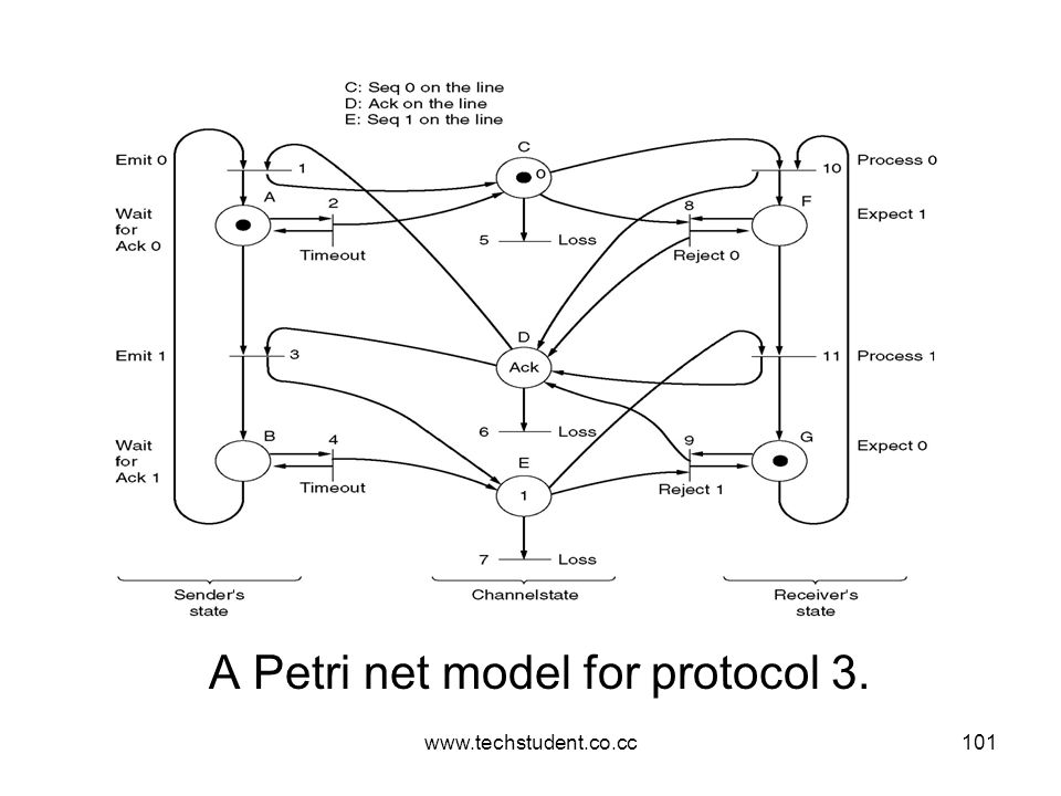
A Petri net model for protocol 3.
102
Transition 1 :transmission of frame 0 by the sender normally.
From fig, there r no composite states: here the sender’s state, channel state, and rxers state r represented separately. Transition 1 :transmission of frame 0 by the sender normally. Transition 2 : 1:transmission of frame 0 on a Time out. Transition 3 and Transition 4: for frame 1 Transition 5,6 and 7: correspond to the loss of frame 0,an ACK and frame 1 respectively. Transition 8 & 9 occurs when a data frame with wrong seq no arrives at the rxer. Transitions 10 & 11 represent the arrival at the rxer of the next frame in sequence and its delivery to the n/w layer

103
Example Data Link Protocols
104
Examples HDLC - HIGH LEVEL DATA LINK CONTROL: HDLC
CCITT Adopted HDLC for its LAP (Link Access Procedure) as part of the X.25 network interface std, but later modified it to LAPB to make it more compatible with the later version of HDLC A connection oriented 64Kbps network using either virtual or permanent circuits. This protocol is Bit oriented (uses bit stuffing and bit delimiters). Frame structure of all bit oriented protocols
 as part of the X.25 network interface std, but later modified it to LAPB to make it more compatible with the later version of HDLC. A connection oriented 64Kbps network using either virtual or permanent circuits. This protocol is Bit oriented (uses bit stuffing and bit delimiters). Frame structure of all bit oriented protocols.")
105
Address: used to identify different terminals
Control:field is used for seq numbers,acks etc. Data: contain arbitrary infrmn. Checksum: field si a minor variation on the well known CRC-CCITT as the generator polynomial. The minimum frame contains 3 fields and total 32 bits excluding the flags on either end.

106
Information, Supervisory, and Unnumbered.
3 kinds of frames: Information, Supervisory, and Unnumbered. Control fields of these 3 r given: The protocol uses a sliding window ,with a 3 bit seq number. Up to 7 un acknowledged frames may b outstanding at any instant. Seq: sequence number Next:piggy backed ack P/F:Poll/Final:is used when a computer is polling a group of terminals. When used as P the computer is inviting the terminal to send data. All the frame sent by the terminal except the final one hav the P/F bit as P.the final one is set to F.

107
Type: used to distinguish various types of supervisory frames.
Type 0 :is an ACK frame (RECEIVE READY) used to indicate the next frame expected. Type 1:is a NACK frame (REJECT) used to indicate that a txn error has been detected. The Next field indicates the first frame in sequence not rxed correctly. The sender is required to retransmit all outstanding frames starting at next. Type 2: is RECEIVE NOT READY .It acknowledges all frames up to but not including Next but it tells the the sender to stop sending. Type 3: is the SELECTIVE REJECT.it calls for retxn of only the frame specified. Unnumbered frames are used for control purposes but can also b used to carry data when un reliable connectionless service is called for.
 used to indicate the next frame expected. Type 1:is a NACK frame (REJECT) used to indicate that a txn error has been detected. The Next field indicates the first frame in sequence not rxed correctly. The sender is required to retransmit all outstanding frames starting at next. Type 2: is RECEIVE NOT READY .It acknowledges all frames up to but not including Next but it tells the the sender to stop sending. Type 3: is the SELECTIVE REJECT.it calls for retxn of only the frame specified. Unnumbered frames are used for control purposes but can also b used to carry data when un reliable connectionless service is called for.")
108
Examples DLL In The Internet 1.SLIP-Serial Line IP SLIP-older one
2 such protocols widely used in the internet r SLIP and PPP. 1.SLIP-Serial Line IP SLIP-older one Devised by Rick Adams in 1984 to connect sun workstations to the Internet over a dial-up line using a modem. The work station just sends raw IP packets over the line, with a special flag byte (0xC0) at the end for framing. If the flag byte occurs inside the IP packet a form of char. Stuffing is used and 2 byte sequence(0xDB,0xDC) is sent in its place. More recent versions of SLIP do some TCP and IP header compression. It is still widely used but has some serious problems: It does not do any error detection or correction It supports only IP Each side must know others IP in advance Doe not provide any form of authentication Not an approved internet standard.
 at the end for framing. If the flag byte occurs inside the IP packet a form of char. Stuffing is used and 2 byte sequence(0xDB,0xDC) is sent in its place. More recent versions of SLIP do some TCP and IP header compression. It is still widely used but has some serious problems: It does not do any error detection or correction. It supports only IP. Each side must know others IP in advance. Doe not provide any form of authentication. Not an approved internet standard.")
109
2.PPP-Point to Point Protocols
2.PPP-Point to Point Protocols To improve the above situation IETF (InternetEnggTaskForce) set up a group to device a DL protocol for point-point lines that solved all these problems and became an official std. PPP handles: Error detection,Supprots multiple protocols,allows IP addresses to b negotiated at connection time, permits authentication, etc. PPP provides 3 things: 1)A framing method that unambiguously delineates the end of the frame and the start of the next one. 2)A link protocol for bringing lines up, testing them, negotiating options, and bringing them down when they r no longer needed. called LCP-Link Control Protocol 3)A way to negotiate network-layer options in a way that is independent of the n/w layer protocol to b used- ie,Different NCP (Network Control Protocol)
 set up a group to device a DL protocol for point-point lines that solved all these problems and became an official std. PPP handles: Error detection,Supprots multiple protocols,allows IP addresses to b negotiated at connection time, permits authentication, etc. PPP provides 3 things: 1)A framing method that unambiguously delineates the end of the frame and the start of the next one. 2)A link protocol for bringing lines up, testing them, negotiating options, and bringing them down when they r no longer needed. called LCP-Link Control Protocol. 3)A way to negotiate network-layer options in a way that is independent of the n/w layer protocol to b used- ie,Different NCP (Network Control Protocol)")
110
Working of PPP Consider the case of a home user calling up an ISP to make a home PC a temp internet host. PC first calls the ISP’s router via a modem. After getting answer from modem establish a physical connection thru the phone. The PC sends the router a series of LCP packets in the pay load field of one or more PPP frames. These packets and their responses ,select the PPP parameters to b used. After agreeing this a series of NCP packets r sent to configure the n/w layer. The PC wants to run a TCP/IP protocol stack and need an IP address. There r not enough IP addresses to go around- normally each ISP gets a block of them and then dynamically assigns 1 to each newly attached PC for the duration of its login session.

111
The NCP for IP used to do the IP adrs assignment.
The PC is now an Internet host and can send and receive IP packets. When the user is finished ,NCP is used to tear down the n/w layer connection and free up the IP adrs. Then LCP is used to shutdown the DLL connection. Finally computer tells the modem to hang up the phone ,releasing the phy.layer connection.

112
The Data Link Layer in the Internet
A home personal computer acting as an internet host.

113
PPP full frame format for unnumbered mode operation
Address: always set to to indicate that all stations r to accept the frame. Control: indicates an unnumbered frame.(as default PPP does not provide reliable txn using seq numbers and ack) Protocol: job is to tell what kind of packet is in the payload field. Codes r defined for LCP,NCP, IP,IPX etc. Protocols starting with a 0 bit r n/w layer protocols such as IP,IPX etc Starting with 1 bit r used to negotiate other protocols (like LCP,NCP etc). Payload :field is variable length up to some max (Default is 1500 bytes) Checksum: normally 2 bytes but 4 bytes can b negotiated
 Protocol: job is to tell what kind of packet is in the payload field. Codes r defined for LCP,NCP, IP,IPX etc. Protocols starting with a 0 bit r n/w layer protocols such as IP,IPX etc. Starting with 1 bit r used to negotiate other protocols (like LCP,NCP etc). Payload :field is variable length up to some max (Default is 1500 bytes) Checksum: normally 2 bytes but 4 bytes can b negotiated.")
114
A simplified phase diagram for bring a line up and down.
In summary ,PPP is a multiprotocol framing mechanism suitable for use over modems, HDLC bit-serial lines, SONET and other physical layers. It supports error detection, header compression etc… A simplified phase diagram for bring a line up and down.

115
Examples DLL in ATM:

116
2.8 Error Detection and Correction
It is physically impossible for any data recording or transmission medium to be 100% perfect 100% of the time over its entire expected useful life. As more bits are packed onto a square centimeter of disk storage, as communications transmission speeds increase, the likelihood of error increases-- sometimes geometrically. Thus, error detection and correction is critical to accurate data transmission, storage and retrieval.

117
2.8 Error Detection and Correction
Check digits, appended to the end of a long number can provide some protection against data input errors. The last character of UPC barcodes and ISBNs are check digits. Longer data streams require more economical and sophisticated error detection mechanisms. Cyclic redundancy checking (CRC) codes provide error detection for large blocks of data.
 codes provide error detection for large blocks of data.")
118
2.8 Error Detection and Correction
Checksums and CRCs are examples of systematic error detection. In systematic error detection a group of error control bits is appended to the end of the block of transmitted data. This group of bits is called a syndrome. CRCs are polynomials over the modulo 2 arithmetic field. The mathematical theory behind modulo 2 polynomials is beyond our scope. However, we can easily work with it without knowing its theoretical underpinnings.

119
2.8 Error Detection and Correction
Modulo 2 arithmetic works like clock arithmetic. In clock arithmetic, if we add 2 hours to 11:00, we get 1:00. In modulo 2 arithmetic if we add 1 to 1, we get 0. The addition rules couldn’t be simpler: 0 + 0 = = 1 1 + 0 = = 0 You will fully understand why modulo 2 arithmetic is so handy after you study digital circuits in Chapter 3.

120
2.8 Error Detection and Correction
Find the quotient and remainder when is divided by 1101 in modulo 2 arithmetic. As with traditional division, we note that the dividend is divisible once by the divisor. We place the divisor under the dividend and perform modulo 2 subtraction.

121
2.8 Error Detection and Correction
Find the quotient and remainder when is divided by 1101 in modulo 2 arithmetic… Now we bring down the next bit of the dividend. We see that is not divisible by So we place a zero in the quotient.

122
2.8 Error Detection and Correction
Find the quotient and remainder when is divided by 1101 in modulo 2 arithmetic… 1010 is divisible by 1101 in modulo 2. We perform the modulo 2 subtraction.

123
2.8 Error Detection and Correction
Find the quotient and remainder when is divided by 1101 in modulo 2 arithmetic… We find the quotient is 1011, and the remainder is 0010. This procedure is very useful to us in calculating CRC syndromes. Note: The divisor in this example corresponds to a modulo 2 polynomial: X 3 + X

124
2.8 Error Detection and Correction
Suppose we want to transmit the information string: The receiver and sender decide to use the (arbitrary) polynomial pattern, 1101. The information string is shifted left by one position less than the number of positions in the divisor. The remainder is found through modulo 2 division (at right) and added to the information string: =
 polynomial pattern, The information string is shifted left by one position less than the number of positions in the divisor. The remainder is found through modulo 2 division (at right) and added to the information string: =")
125
2.8 Error Detection and Correction
If no bits are lost or corrupted, dividing the received information string by the agreed upon pattern will give a remainder of zero. We see this is so in the calculation at the right. Real applications use longer polynomials to cover larger information strings. Some of the standard poly-nomials are listed in the text.

126
2.8 Error Detection and Correction
Data transmission errors are easy to fix once an error is detected. Just ask the sender to transmit the data again. In computer memory and data storage, however, this cannot be done. Too often the only copy of something important is in memory or on disk. Thus, to provide data integrity over the long term, error correcting codes are required.

127
2.8 Error Detection and Correction
Hamming codes and Reed-Soloman codes are two important error correcting codes. Reed-Soloman codes are particularly useful in correcting burst errors that occur when a series of adjacent bits are damaged. Because CD-ROMs are easily scratched, they employ a type of Reed-Soloman error correction. Because the mathematics of Hamming codes is much simpler than Reed-Soloman, we discuss Hamming codes in detail.

128
2.8 Error Detection and Correction
Hamming codes are code words formed by adding redundant check bits, or parity bits, to a data word. The Hamming distance between two code words is the number of bits in which two code words differ. The minimum Hamming distance for a code is the smallest Hamming distance between all pairs of words in the code. This pair of bytes has a Hamming distance of 3:

129
2.8 Error Detection and Correction
The minimum Hamming distance for a code, D(min), determines its error detecting and error correcting capability. For any code word, X, to be interpreted as a different valid code word, Y, at least D(min) single-bit errors must occur in X. Thus, to detect k (or fewer) single-bit errors, the code must have a Hamming distance of D(min) = k + 1.
, determines its error detecting and error correcting capability. For any code word, X, to be interpreted as a different valid code word, Y, at least D(min) single-bit errors must occur in X. Thus, to detect k (or fewer) single-bit errors, the code must have a Hamming distance of D(min) = k")
130
2.8 Error Detection and Correction
Hamming codes can detect D(min) - 1 errors and correct errors Thus, a Hamming distance of 2k + 1 is required to be able to correct k errors in any data word. Hamming distance is provided by adding a suitable number of parity bits to a data word.
 - 1 errors and correct errors. Thus, a Hamming distance of 2k + 1 is required to be able to correct k errors in any data word. Hamming distance is provided by adding a suitable number of parity bits to a data word.")
131
2.8 Error Detection and Correction
Suppose we have a set of n-bit code words consisting of m data bits and r (redundant) parity bits. An error could occur in any of the n bits, so each code word can be associated with n erroneous words at a Hamming distance of 1. Therefore,we have n + 1 bit patterns for each code word: one valid code word, and n erroneous words.
 parity bits. An error could occur in any of the n bits, so each code word can be associated with n erroneous words at a Hamming distance of 1. Therefore,we have n + 1 bit patterns for each code word: one valid code word, and n erroneous words.")
132
2.8 Error Detection and Correction
With n-bit code words, we have 2 n possible code words consisting of 2 m data bits (where n = m + r). This gives us the inequality: (n + 1) 2 m 2 n Because n = m + r, we can rewrite the inequality as: (m + r + 1) 2 m 2 m + r or (m + r + 1) 2 r This inequality gives us a lower limit on the number of check bits that we need in our code words.
. This gives us the inequality: (n + 1) 2 m 2 n. Because n = m + r, we can rewrite the inequality as: (m + r + 1) 2 m 2 m + r or (m + r + 1) 2 r. This inequality gives us a lower limit on the number of check bits that we need in our code words.")
133
2.8 Error Detection and Correction
Suppose we have data words of length m = 4. Then: (4 + r + 1) 2 r implies that r must be greater than or equal to 3. This means to build a code with 4-bit data words that will correct single-bit errors, we must add 3 check bits. Finding the number of check bits is the hard part. The rest is easy.
 2 r. implies that r must be greater than or equal to 3. This means to build a code with 4-bit data words that will correct single-bit errors, we must add 3 check bits. Finding the number of check bits is the hard part. The rest is easy.")
134
2.8 Error Detection and Correction
Suppose we have data words of length m = 8. Then: (8 + r + 1) 2 r implies that r must be greater than or equal to 4. This means to build a code with 8-bit data words that will correct single-bit errors, we must add 4 check bits, creating code words of length 12. So how do we assign values to these check bits?
 2 r. implies that r must be greater than or equal to 4. This means to build a code with 8-bit data words that will correct single-bit errors, we must add 4 check bits, creating code words of length 12. So how do we assign values to these check bits")
135
2.8 Error Detection and Correction
With code words of length 12, we observe that each of the digits, 1 though 12, can be expressed in powers of 2. Thus: 1 = = = 2 = = = 3 = = = 4 = = = 1 (= 20) contributes to all of the odd-numbered digits. 2 (= 21) contributes to the digits, 2, 3, 6, 7, 10, and 11. . . . And so forth . . . We can use this idea in the creation of our check bits.
 contributes to all of the odd-numbered digits. 2 (= 21) contributes to the digits, 2, 3, 6, 7, 10, and And so forth We can use this idea in the creation of our check bits.")
136
2.8 Error Detection and Correction
Using our code words of length 12, number each bit position starting with 1 in the low-order bit. Each bit position corresponding to an even power of 2 will be occupied by a check bit. These check bits contain the parity of each bit position for which it participates in the sum.

137
2.8 Error Detection and Correction
Since 2 (= 21) contributes to the digits, 2, 3, 6, 7, 10, and 11. Position 2 will contain the parity for bits 3, 6, 7, 10, and 11. When we use even parity, this is the modulo 2 sum of the participating bit values. For the bit values shown, we have a parity value of 0 in the second bit position. What are the values for the other parity bits?
 contributes to the digits, 2, 3, 6, 7, 10, and 11. Position 2 will contain the parity for bits 3, 6, 7, 10, and 11. When we use even parity, this is the modulo 2 sum of the participating bit values. For the bit values shown, we have a parity value of 0 in the second bit position. What are the values for the other parity bits")
138
2.8 Error Detection and Correction
The completed code word is shown above. Bit 1checks the digits, 3, 5, 7, 9, and 11, so its value is 1. Bit 4 checks the digits, 5, 6, 7, and 12, so its value is 1. Bit 8 checks the digits, 9, 10, 11, and 12, so its value is also 1. Using the Hamming algorithm, we can not only detect single bit errors in this code word, but also correct them!

139
2.8 Error Detection and Correction
Suppose an error occurs in bit 5, as shown above. Our parity bit values are: Bit 1 checks digits, 3, 5, 7, 9, and 11. Its value is 1, but should be zero. Bit 2 checks digits 2, 3, 6, 7, 10, and 11. The zero is correct. Bit 4 checks digits, 5, 6, 7, and 12. Its value is 1, but should be zero. Bit 8 checks digits, 9, 10, 11, and 12. This bit is correct.

140
2.8 Error Detection and Correction
We have erroneous bits in positions 1 and 4. With two parity bits that don’t check, we know that the error is in the data, and not in a parity bit. Which data bits are in error? We find out by adding the bit positions of the erroneous bits. Simply, = 5. This tells us that the error is in bit 5. If we change bit 5 to a 1, all parity bits check and our data is restored.

141
ELEMENTARY DLL PROTOCOLS

142
Assumptions: Physical, Data link and network layer are independent process that communicate by passing message Machine A wants to send long stream of data to machine B using reliable, connection-oriented service A have an infinite supply of data ready to send and never has to wait for data to be produced

143
Checksum is incorrect event=cksum_err
Suitable library procedures to_physical_layer to send a frame and from_physical_layer to receive a frame Procedure wait_for_event(&event) waits for something to happen and only returns when a frame has arrived Checksum is incorrect event=cksum_err Undamaged frame event=frame_arrival
 waits for something to happen and only returns when a frame has arrived. Checksum is incorrect event=cksum_err. Undamaged frame event=frame_arrival.")
144
Data Structures used are:
boolean - value true/false seq_nr - int used to no: frames, value 0 to MAX_SEQ packet – unit of info exchanged, value MAX_PKT bytes frame_kind – data,ack,nak frame – consist of four fields

145
kind –whether or not there is any data in frame seq ack
info – contains a single packet in data frame - not used in control frame

146
Elementary Data Link Protocols
An Unrestricted Simplex Protocol A Simplex Stop-and-Wait Protocol A Simplex Protocol for a Noisy Channel

147
typedef enum {false, true} boolean; /* boolean type */
#define MAX PKT /* determines packet size in bytes */ typedef enum {false, true} boolean; /* boolean type */ typedef unsigned int seq_nr; /* sequence or ack numbers */ typedef struct { unsigned char data[MAX PKT]; } packet; /* packet definition */ typedef enum {data, ack, nak} frame_kind; /* frame kind definition */ typedef struct { /* frames are transported in this layer */ frame_kind kind; /* what kind of a frame is it? */ seq_nr seq; /* sequence number */ seq_nr ack; /* acknowledgement number */ packet info; /* the network layer packet */ } frame;

148
DLL Protocols void wait_for_event(event_type *event );
/* 1. Wait for an event to happen; return its type in event. */ void wait_for_event(event_type *event ); /* 2. Fetch a packet from the network layer for transmission on the channel. */ void from_network_layer( packet *p); /* 3. Deliver information from an inbound frame to the network layer. */ void to_network_layer( packet *p); /* 4. Go get an inbound frame from the physical layer and copy it to r. */ void from_physical_layer( packet *p); /* 5. Pass the frame to the physical layer for transmission. */ void to_physical_layer( packet *p);
; /* 2. Fetch a packet from the network layer for transmission on the channel. */ void from_network_layer( packet *p); /* 3. Deliver information from an inbound frame to the network layer. */ void to_network_layer( packet *p); /* 4. Go get an inbound frame from the physical layer and copy it to r. */ void from_physical_layer( packet *p); /* 5. Pass the frame to the physical layer for transmission. */ void to_physical_layer( packet *p);")
149
/* 7. Stop the clock and disable the timeout event. */
void stop_timer(seq_nr k); /* 8. Start an auxiliary timer and enable the ack_timeout event. */ void start_ack_timer(void); /* 9. Stop the auxiliary timerand disable the ack_timeout event. */ void stop_ack_timer(void); /* 10. Allow the network layer to cause a network_layer_event. */ void enable_network_layer( void ); /* 11. Forbid the network layer from causing a network_layer_event. */ void disable_network_layer( void );
; /* 8. Start an auxiliary timer and enable the ack_timeout event. */ void start_ack_timer(void); /* 9. Stop the auxiliary timerand disable the ack_timeout event. */ void stop_ack_timer(void); /* 10. Allow the network layer to cause a network_layer_event. */ void enable_network_layer( void ); /* 11. Forbid the network layer from causing a network_layer_event. */ void disable_network_layer( void );")
150
Unrestricted Simplex Protocol
Assumptions: Data transmission in one direction only (simplex). No errors take place on the physical channel. The sender/receiver can generate/consume an infinite amount of data. Always ready for sending/receiving.
. No errors take place on the physical channel. The sender/receiver can generate/consume an infinite amount of data. Always ready for sending/receiving.")
151
Protocol consists of two distinct procedures a sender a receiver
The sender runs in the data link layer of the source machine The receiver runs in the data link layer of the destination machine No sequence numbers or ack are used here, so MAX_SEQ is not needed.

153
/* Protocol 1 (utopia) provides for data transmission in one direction only, from sender to receiver. The communication channel is assumed to be error free and the receiver is assumed to be able to process all the input infinitely fast. Consequently, the sender just sits in a loop pumping data out onto the line as fast as it can. */ typedef enum {frame_arrival} event_type; #include "protocol.h" void sender1(void) { frame s; /* buffer for an outbound frame */ packet buffer; /* buffer for an outbound packet */ while (true) { from_network_layer(&buffer); /* go get something to send */ s.info = buffer; /* copy it into s for transmission */ to_physical_layer(&s); /* send it on its way */ }
 { frame s; /* buffer for an outbound frame */ packet buffer; /* buffer for an outbound packet */ while (true) { from_network_layer(&buffer); /* go get something to send */ s.info = buffer; /* copy it into s for transmission */ to_physical_layer(&s); /* send it on its way */ }")
154
Simplex Stop-and-Wait Protocol
Assumptions: No longer assume receiver can process incoming data infinitely fast. Sender ships one frame and then waits for acknowledgment (stop and wait.) Data transmission is one directional, but must have bi-directional line. Could have a half-duplex (one direction at a time) physical channel. Commn channel is error free
 Data transmission is one directional, but must have bi-directional line. Could have a half-duplex (one direction at a time) physical channel. Commn channel is error free.")
156
typedef enum {frame_arrival} event_type; #include "protocol.h“
void sender2(void) { frame s; /* buffer for an outbound frame */ packet buffer; /* buffer for an outbound packet */ event_type event; /* frame_arrival is the only possibility */ while (true) { from_network_layer(&buffer); /* go get something to send */ s.info = buffer; /* copy it into s for transmission */ to_physical_layer(&s); /* send it on its way */ wait_for_event(&event); /* do not proceed until given the go ahead */ }
 { frame s; /* buffer for an outbound frame */ packet buffer; /* buffer for an outbound packet */ event_type event; /* frame_arrival is the only possibility */ while (true) { from_network_layer(&buffer); /* go get something to send */ s.info = buffer; /* copy it into s for transmission */ to_physical_layer(&s); /* send it on its way */ wait_for_event(&event); /* do not proceed until given the go ahead */ }")
157
event_type event; /* filled in by wait, but not used here */
void receiver2(void) { frame r, s; event_type event; /* filled in by wait, but not used here */ while (true) { wait_for_event(&event); /* only possibility is frame arrival */ From_physical_layer(&r); /* go get the inbound frame */ To_network_layer(&r.info); /* pass the data to the network layer */ to_physical_layer(&s); /* send a dummy frame to awaken sender */ }
 { frame r, s; event_type event; /* filled in by wait, but not used here */ while (true) { wait_for_event(&event); /* only possibility is frame arrival */ From_physical_layer(&r); /* go get the inbound frame */ To_network_layer(&r.info); /* pass the data to the network layer */ to_physical_layer(&s); /* send a dummy frame to awaken sender */ }")
158
Simplex Protocol for Noisy Channel
Assumptions: The channel is noisy and we can lose frames (they never arrive). Simple approach, add a time-out to the sender so if no ACK after a certain period, it retransmits the frame. Scenario of a bug that could happen if we’re not careful: A transmits frame one B receives A1 B generates ACK ACK is lost A times out, retransmits B gets duplicate copy of A1 (and sends it on to network layer.)
. Simple approach, add a time-out to the sender so if no ACK after a certain period, it retransmits the frame. Scenario of a bug that could happen if we’re not careful: A transmits frame one. B receives A1. B generates ACK. ACK is lost. A times out, retransmits. B gets duplicate copy of A1 (and sends it on to network layer.)")
159
Positive Acknowledgment with Retransmission (PAR):
Use a sequence number. 1-bit is sufficient for this simple case because only concerned about two successive frames (m and m+1) Positive Acknowledgment with Retransmission (PAR): Or ARQ(Automatic Repeat reQuest) Sender waits for positive acknowledgment before advancing to the next data item. This one also transmits data only in 1 direction. It can handle lost frames-it requires the time out interval to be long enough to prevent premature timeouts. If the sender time outs too early ,while the ack is still on the way it will send a duplicate .
 Positive Acknowledgment with Retransmission (PAR): Or ARQ(Automatic Repeat reQuest) Sender waits for positive acknowledgment before advancing to the next data item. This one also transmits data only in 1 direction. It can handle lost frames-it requires the time out interval to be long enough to prevent premature timeouts. If the sender time outs too early ,while the ack is still on the way it will send a duplicate .")
161
/*Protocol 3(PAR) allows unidirectional data flow over an unreliable channel*/
#define MAX_SEQ 1 /* must be 1 for protocol 3 */ typedef enum {frame_arrival, cksum_err, timeout } event_type; #include "protocol.h“ void sender3(void) { seq_nr next_frame_to_send;/* Seq number of next outgoing frame */ frame s; /* buffer for an outbound frame */ packet buffer; /* buffer for an outbound packet */ event_type event; /* frame_arrival is the only possibility */ next_frame_to_send = 0; from_network_layer(&buffer); /* go get something to send */
 { seq_nr next_frame_to_send;/* Seq number of next outgoing frame */ frame s; /* buffer for an outbound frame */ packet buffer; /* buffer for an outbound packet */ event_type event; /* frame_arrival is the only possibility */ next_frame_to_send = 0; from_network_layer(&buffer); /* go get something to send */")
162
s.info = buffer; /* copy it into s for transmission */
while (true) { s.info = buffer; /* copy it into s for transmission */ s.seq = next_frame_to_send;/* insert sequence number in frame */ to_physical_layer(&s); /* send it on its way */ start_timer( s.seq); /* if answer takes too long, time out */ wait_for_event(&event); /* frame arrival or cksum err, or timeout */ if ( event == frame_arrival) { from_physical_layers(&s); /* Get the ACK */ if ( s.ack == next_frame_to_send ) { from_network_layer( &buffer ); /* get the next one to send */ inc( next_frame_to_send );/* invert next_frame_to_send */ }
 { s.info = buffer; /* copy it into s for transmission */ s.seq = next_frame_to_send;/* insert sequence number in frame */ to_physical_layer(&s); /* send it on its way */ start_timer( s.seq); /* if answer takes too long, time out */ wait_for_event(&event); /* frame arrival or cksum err, or timeout */ if ( event == frame_arrival) { from_physical_layers(&s); /* Get the ACK */ if ( s.ack == next_frame_to_send ) { from_network_layer( &buffer ); /* get the next one to send */ inc( next_frame_to_send );/* invert next_frame_to_send */ }")
163
seq_nr frame_expected; frame r, s; event_type event; while (true) {
void receiver3(void) { seq_nr frame_expected; frame r, s; event_type event; while (true) { wait_for_event(&event); /* only possibility is frame arrival */ if ( frame == event_arrival ) { /* A valid frame has arrived */ from_physical_layer(&r); /* go get the inbound frame */ if ( r.seq == frame_expected ) { /* This is what we’ve been waiting for */ to_network_layer(&r.info); /* pass the data to the network layer */ inc(frame_expected); /* next time expect the other seq # */ } to_physical_layer(&s); /* send a dummy frame to awaken sender */
 { seq_nr frame_expected; frame r, s; event_type event; while (true) { wait_for_event(&event); /* only possibility is frame arrival */ if ( frame == event_arrival ) { /* A valid frame has arrived */ from_physical_layer(&r); /* go get the inbound frame */ if ( r.seq == frame_expected ) { /* This is what we’ve been waiting for */ to_network_layer(&r.info); /* pass the data to the network layer */ inc(frame_expected); /* next time expect the other seq # */ } to_physical_layer(&s); /* send a dummy frame to awaken sender */")
164
SLIDING WINDOW PROTOCOLS

165
Sliding Window Protocols
Use more realistic Two-way communication. 2 kinds of frames (containing a "kind" field): Data ACK containing (sequence number of last correctly received frame). Piggybacking – the technique of temporarily delaying outgoing ack so that they can b attached on to the next outgoing data frame. Piggybacking issue: For better use of bandwidth, how long should we wait for outgoing data frame before sending the ACK on its own.
: Data. ACK containing (sequence number of last correctly received frame). Piggybacking – the technique of temporarily delaying outgoing ack so that they can b attached on to the next outgoing data frame. Piggybacking issue: For better use of bandwidth, how long should we wait for outgoing data frame before sending the ACK on its own.")
166
If new packet arrives quickly, ack is piggybacked onto it
Otherwise dll sends a separate ack frame Next 3 protocols are more robust and continue to function even under pathological conditions

167
Sliding Window Protocols
A One-Bit Sliding Window Protocol A Protocol Using Go Back N A Protocol Using Selective Repeat

168
Max is usually 2n-1 so the seq no. fits in an n-bit field. Basic Idea:
In SWP each outbound frame contains a seq no. ranging frm 0 to some max. Max is usually 2n-1 so the seq no. fits in an n-bit field. Basic Idea: At any instant of time the sender maintains a set of sequence numbers corresponding to frames it is permitted to send. This frames r said to b in sending window Rxer also maintains a rxing window corresponding to the set of frames it is permitted to accept.

169
When an ack comes in ,the lower edge is advanced by one.
The seq. nos within the senders window represent frames sent but not yet acknowledged. Whenever a new packet arrives from the n/w layer it is given the next highest seq.no,and the upper edge of the window is advanced by one. When an ack comes in ,the lower edge is advanced by one. In this way the window continuously maintains a list of un acknowledge frames.

170
The rxing dll’s window corresponds to the the frames it may accept .
If the max window size is n, the sender needs n buffers to hold the un acknowledged frame. The rxing dll’s window corresponds to the the frames it may accept . Any frame falling outside the window is discarded. When a frame whose seq number is equal to the lower edge of the window is rxed,it is passed to the n/w layer, an ack is generated and the window is rotated by one. Window size 1 means that the DLL accepts frames in order-for larger window size this is not so.

171
One Bit Sliding Window Protocol
Here window size is 1 Sequence number is of 1 bit (ie,0 or 1) Use stop-and-wait: sender transmits a frame and waits for its ACK before sending the next one
 Use stop-and-wait: sender transmits a frame and waits for its ACK before sending the next one.")
172
SLIDING WINDOW PROTOCOLS

173
1.One Bit Sliding Window Protocol
Here window size is 1 Sequence number is of 1 bit (ie,0 or 1) Use stop-and-wait: sender transmits a frame and waits for its ACK before sending the next one It is very inefficient Ack field contains no: of last frame received without error
 Use stop-and-wait: sender transmits a frame and waits for its ACK before sending the next one. It is very inefficient. Ack field contains no: of last frame received without error.")
175
OTHER ISSUES Problem with stop and wait protocols is that sender can only have one unACKed frame outstanding. This is a consequence of the rule requiring a sender to wait for an acknowledgement bfor sending another frame. If this restriction is relaxed, better efficiency can be achieved. i.e, allowing the sender to transmit up to w frames before blocking, instead of 1. With an appropriate choice of w the sender will b able to continuously transmit frames for a time interval equal to the round-trip transit time without filling up the window. This is known as pipelining.

176
PIPELINING Problems with pipelining
Sender does not wait for each frame to be ACK'ed. Rather it sends many frames with the assumption that they will arrive. Must still get back ACKs for each frame. Provides more efficient use of transmit bandwidth, but error handling is more complex. What if 20 frames transmitted, and the second has an error. Frames 3-20 will be ignored at receiver side? Sender will have to retransmit. 2 basic approach in dealing with errors in pipelining Go back n Selective repeat

177
Go-Back-n Protocol If receiver sees bad frames or missing sequence numbers, subsequent frames are discarded No ACKs for discarded frames Equivalent to receiver's window size of one The DLL refuses to accept any frame except the next one it must give to the n/w layer If the sender’s widow fills up before the timer runs out, the pipeline will begin to empty. Eventually, the sender will time out and retransmit all unacknowledged frames in order, starting with the damaged or lost one

178
Disad: waste much of the b/w if the error rate is high
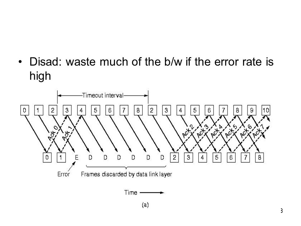
179
Send window for Go-Back-N ARQ
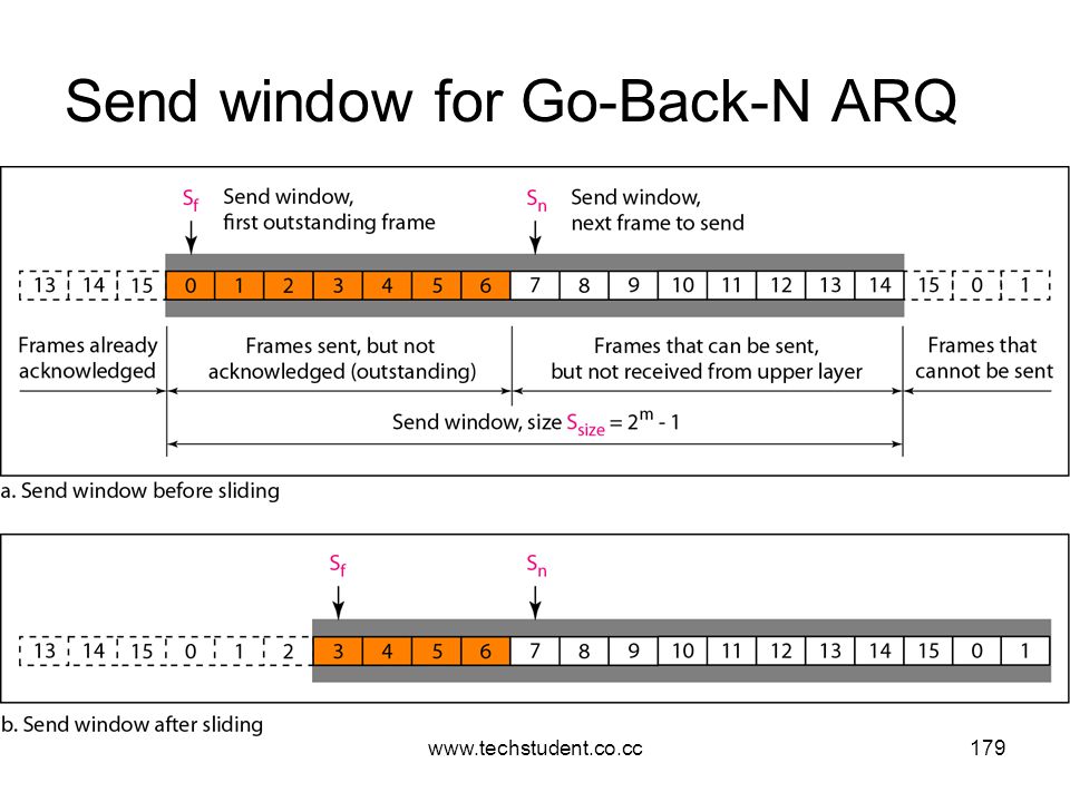
180
Receive window for Go-Back-N ARQ

181
If no error, ACK as usual with next frame expected
Uses window to control number of outstanding frames If error, reply with rejection Discard that frame and all future frames until error frame received correctly Transmitter must go back and retransmit that frame and all subsequent frames

182
Selective repeat Also called selective retransmission
Only rejected frames are retransmitted Subsequent frames are accepted by the receiver and buffered Minimizes retransmission Receiver must maintain large buffer More complex logic in transmitter

183
the rxing DLL have to store all the correct frames following the bad ones.
When the sender finally notices that something is wrong ,it just retransmits the one bad frame, not all its successors,. If the second try succeeds, the rxing DLL will now have many correct frames in sequence ,so they can all be handed off to the n/w layer quickly, and the highest number acknowledged.

185
Protocol Specification & Verification

186
Deals with techniques for specifying and verifying protocols
1.Finite State Machine model 2.Petri Net model

187
1.Finite State Machine models
Each protocol machine (sender/ rxer) is always in a specific state at every instant of time. Eg: The rxer in protocol 3 has 2 important states : waiting for frame0 or waiting for frmae1. Typically the states are chosen to be those instants that the protocol m/c is waiting for the next event to happen (eg: wait (event)). The state of the complete s/m is the combination of the 2 protocol m/cs and the channel. The state of the channel is represented by its contents. Using protocol 3 the channel has 4 possible states: 0 frame or 1 frame moving from sender to rxer, an ack going the other way, an empty channel.
 is always in a specific state at every instant of time. Eg: The rxer in protocol 3 has 2 important states : waiting for frame0 or waiting for frmae1. Typically the states are chosen to be those instants that the protocol m/c is waiting for the next event to happen (eg: wait (event)). The state of the complete s/m is the combination of the 2 protocol m/cs and the channel. The state of the channel is represented by its contents. Using protocol 3 the channel has 4 possible states: 0 frame or 1 frame moving from sender to rxer, an ack going the other way, an empty channel.")
188
Transitions occur when some event happens
From each state there are 0 or more possible transitions to other states. Transitions occur when some event happens In a protocol m/c transitions occur when a frame is sent, when a frame arrives, when a timer goes off etc. One particular state is designated as initial state-corresponds to the description of the s/m when it starts running. From the initial state some or all of the other states can be reached by a sequence of transitions. Using some well-known techniques from graph theory, it is possible to determine which states are reachable and which are not. This technique is called reachability analysis. This can be helpful in determining if a protocol is correct or not.

189
S: is the set of states the processes and channels can be in
Formally, a finite state m/c can be regarded as a quadruple (S,M,I,T) where: S: is the set of states the processes and channels can be in M: is the set of frames that can be exchanged over the channel I: is the set of initial states of the processes. T: is the set of transitions between states. At the beginning of time ,all processes are in their initial states. Then events begin to happen-like frames becoming available for txn or timers going off. Each event may cause on of the processes or the channel to take an action and switch to a new state. Eg: Finite state m/c model of protocol 3
 where: S: is the set of states the processes and channels can be in. M: is the set of frames that can be exchanged over the channel. I: is the set of initial states of the processes. T: is the set of transitions between states. At the beginning of time ,all processes are in their initial states. Then events begin to happen-like frames becoming available for txn or timers going off. Each event may cause on of the processes or the channel to take an action and switch to a new state. Eg: Finite state m/c model of protocol 3.")
190
Each state is labeled by 3 chars-X, Y and Z
Each protocol m/c has 2 states and channel has 4 states- a total of 16 states exist, not all of them reachable from the initial one. Each state is labeled by 3 chars-X, Y and Z Where X is 0/1 corresponding to the frame the sender is trying to send Y is 0/1 corresponding to the frame the rxer expects, Z is 0,1 or A or empty(-) corresponding to the state of the channel. Above eg. Initial state is chosen as (000) i.e, the sender has just sent frame 0,the rxer expects frame 0 and frame 0 is currently on channel. Total 9 transitions r shown. Transition 0 consists of the channel losing its contents. Transition 1 consists of the channel correctly delivering packet 0 to the rxer, with the rxer then changing its state to expect frame 1 and emitting an ACK Transition 1 also corresponds to the rxer delivering packet 0 to the n/w layer.
 corresponding to the state of the channel. Above eg. Initial state is chosen as (000) i.e, the sender has just sent frame 0,the rxer expects frame 0 and frame 0 is currently on channel. Total 9 transitions r shown. Transition 0 consists of the channel losing its contents. Transition 1 consists of the channel correctly delivering packet 0 to the rxer, with the rxer then changing its state to expect frame 1 and emitting an ACK. Transition 1 also corresponds to the rxer delivering packet 0 to the n/w layer.")
191
Eg:Protocol 3 (a) State diagram for protocol 3. (b) Transitions

192
Important property of protocol is absence of deadlock
During normal operation, transition 1,2,3 and 4 are repeated in order over and over. In each cycles,2 packets are delivered, bringing the sender back to the initial state of trying to send a new frame with seq no. 0. If the channel loses frame 0,it makes a transition from state (000) to (00-). Eventually the sender times out (transition 7) and the s/m moves back to (000). The loss of ack requires 2 transitions 7 and 5 or 8 and 6 to repair the damage. Important property of protocol is absence of deadlock
 to (00-). Eventually the sender times out (transition 7) and the s/m moves back to (000). The loss of ack requires 2 transitions 7 and 5 or 8 and 6 to repair the damage. Important property of protocol is absence of deadlock.")
193
EXAMPLE DATA LINK PROTOCOLS

194
Example Data Link Protocols
HDLC – High-Level Data Link Control The Data Link Layer in the Internet

195
HDLC CCITT adopted and modified HDLC for its LAP (Link Access Procedure) as part of X.25 network interface std Later modified it again to LAPB(LAP Balanced). Bit oriented protocol Used for point-to-point and multipoint links Implements ARQ mechanism Developed by ISO Provides both connection oriented and connectionless service
. Bit oriented protocol. Used for point-to-point and multipoint links. Implements ARQ mechanism. Developed by ISO. Provides both connection oriented and connectionless service.")
196
HDLC Station Types Primary station Secondary station Combined station
Controls operation of link Frames issued are called commands Maintains separate logical link to each secondary station Uses unbalanced mode to communicate with secondary Secondary station Under control of primary station Frames issued called responses It also uses unbalanced communication mode Combined station May issue commands and responses

197
HDLC Link Configurations
Unbalanced One primary and one or more secondary stations Supports full duplex and half duplex Balanced Two combined stations Symmetrical Two independent point-to-point unbalanced config Each station has primary and secondary status Each station is logically considered as two stations

198
HDLC Transfer Modes (1) Normal Response Mode (NRM)
Unbalanced configuration Primary initiates transfer to secondary Secondary may only transmit data in response to command from primary Used on multi-drop lines Host computer as primary Terminals as secondary

199
HDLC Transfer Modes (2) Asynchronous Balanced Mode (ABM)
Balanced configuration Either station may initiate transmission without receiving permission Most widely used No polling overhead

200
HDLC Transfer Modes (3) Asynchronous Response Mode (ARM)
Unbalanced configuration Secondary may initiate transmission without permission form primary Primary responsible for line rarely used

201
Frame Structure Synchronous transmission All transmissions in frames
Single frame format for all data and control exchanges

202
Flag Fields Delimit frame at both ends 01111110
May close one frame and open another Receiver hunts for flag sequence to synchronize Bit stuffing used to avoid confusion with data containing 0 inserted after every sequence of five 1s If receiver detects five 1s it checks next bit If 0, it is deleted If 1 and seventh bit is 0, accept as flag Complementary ckt used at receiver to destuff extra 0 & retrieve original data

203
Address: used to identify different terminals
Control: field is used for seq numbers,acks etc. Data: contain actual data Checksum: detect errors that occur during transmission 3 kinds of frames Information frame (I frame) Supervisory frame (S frame) Unnumbered frame (U frame)
 Supervisory frame (S frame) Unnumbered frame (U frame)")
204
Control field of (a) An information frame. (b) A supervisory frame
Control field of (a) An information frame. (b) A supervisory frame. (c) An unnumbered frame.
 An information frame. (b) A supervisory frame. (c) An unnumbered frame.")
205
Information Frame Carry data to be transmitted Seq-frame sequence no:
Next-piggybacked ack P/F-stands for POLL/FINAL P-inviting terminal to send data F-final frame is set to F

206
Supervisory Frame Used to provide error ctrl & flow ctrl info
Various kinds of s-frame based on type field Type 0 Ack frame Called RECEIVE READY Indicate next frame expected

207
Indicates transmission error has been detected Type 2
Negative ack frame Called REJECT Indicates transmission error has been detected Next field indicates seq no: of frame not received correctly Type 2 Called RECEIVE NOT READY Used to temporarily stop sender from transmitting frame Type 3 Called SELECTIVE REJECT Used for transmission of specific frames

208
Unnumbered Frame Used for link management Used for control purposes
Also used to carry data when unreliable connectionless service is called for The type and modifier fields together identify the function of the frame. Typical functions include: RIM Request Initialisation Mode SABM Set Asynchronous Balanced Mode DiSC Disconnect the Link RSET Reset the Link FRMR FRame Reject. ie you sent me a frame which arrived with a totally impossible format.

209
DLL in the Internet 2 protocols widely used in the internet are SLIP and PPP 1.SLIP-Serial Line IP Older one Devised by Rick Adams in 1984 to connect sun workstations to the Internet over a dial-up line using a modem. The work station just sends raw IP packets over the line, with a special flag byte (0xC0) at the end for framing. If the flag byte occurs inside the IP packet a form of char stuffing is used and 2 byte sequence(0xDB,0xDC) is sent in its place. More recent versions of SLIP do some TCP and IP header compression. It is still widely used but has some serious problems: no any error detection or correction supports only IP Each side must know others IP in advance Doe not provide any form of authentication Not an approved internet standard.
 at the end for framing. If the flag byte occurs inside the IP packet a form of char stuffing is used and 2 byte sequence(0xDB,0xDC) is sent in its place. More recent versions of SLIP do some TCP and IP header compression. It is still widely used but has some serious problems: no any error detection or correction. supports only IP. Each side must know others IP in advance. Doe not provide any form of authentication. Not an approved internet standard.")
210
2.PPP-Point to Point Protocol
To improve the above situation IETF (Internet EnggTaskForce) set up a group to device a DL protocol for point-point lines that solved all these problems and became an official std. PPP handles: Error detection, Supports multiple protocols, allows IP addresses to be negotiated at connection time, permits authentication, etc. PPP provides 3 things: 1)A framing method that unambiguously delineates the end of the frame and the start of the next one. 2)A link protocol for bringing lines up, testing them, negotiating options, and bringing them down when they are no longer needed. called LCP-Link Control Protocol 3)A way to negotiate network-layer options in a way that is independent of the n/w layer protocol to be used- ie,Different NCP (Network Control Protocol)
 set up a group to device a DL protocol for point-point lines that solved all these problems and became an official std. PPP handles: Error detection, Supports multiple protocols, allows IP addresses to be negotiated at connection time, permits authentication, etc. PPP provides 3 things: 1)A framing method that unambiguously delineates the end of the frame and the start of the next one. 2)A link protocol for bringing lines up, testing them, negotiating options, and bringing them down when they are no longer needed. called LCP-Link Control Protocol. 3)A way to negotiate network-layer options in a way that is independent of the n/w layer protocol to be used- ie,Different NCP (Network Control Protocol)")
211
Working of PPP Consider the case of a home user calling up an ISP to make a home PC a temp internet host. PC first calls the ISP’s router via a modem. After getting answer from modem establish a physical connection thru the phone. The PC sends the router a series of LCP packets in the pay load field of one or more PPP frames. These packets and their responses ,select the PPP parameters to be used. After agreeing this a series of NCP packets are sent to configure the n/w layer. The PC wants to run a TCP/IP protocol stack and need an IP address. There are not enough IP addresses to go around- normally each ISP gets a block of them and then dynamically assigns 1 to each newly attached PC for the duration of its login session.

212
The NCP for IP used to do the IP adrs assignment.
The PC is now an Internet host and can send and receive IP packets. When the user is finished ,NCP is used to tear down the n/w layer connection and free up the IP adrs. Then LCP is used to shutdown the DLL connection. Finally computer tells the modem to hang up the phone ,releasing the phy.layer connection.

213
Address: always set to to indicate that all stations are to accept the frame. Control: indicates an unnumbered frame.(as default PPP does not provide reliable txn using seq numbers and ack) Protocol: job is to tell what kind of packet is in the payload field. Codes are defined for LCP,NCP, IP,IPX etc. Protocols starting with a 0 bit are n/w layer protocols such as IP,IPX etc Starting with 1 bit are used to negotiate other protocols (like LCP,NCP etc). Payload :field is variable length up to some max (Default is 1500 bytes) Checksum: normally 2 bytes but 4 bytes can be negotiated
 Protocol: job is to tell what kind of packet is in the payload field. Codes are defined for LCP,NCP, IP,IPX etc. Protocols starting with a 0 bit are n/w layer protocols such as IP,IPX etc Starting with 1 bit are used to negotiate other protocols (like LCP,NCP etc). Payload :field is variable length up to some max (Default is 1500 bytes) Checksum: normally 2 bytes but 4 bytes can be negotiated.")
214
MEDIUM ACCESS SUBLAYER

215
Key issue who gets to use the channel
Sublayer of data link layer –MAC (Medium Access Control) sublayer The protocol used to determine who goes next on a multi access channel belong to MAC layer It is important in LANs because it use a multi access channel for their communication
 sublayer. The protocol used to determine who goes next on a multi access channel belong to MAC layer. It is important in LANs because it use a multi access channel for their communication.")
216
The Channel Allocation Problem
Static Channel Allocation in LANs and MANs Dynamic Channel Allocation in LANs and MANs

217
Static Channel Allocation
Traditional way of allocating single channel-FDM (Frequency Division Multiplexing) & TDM (Time Division Multiplexing) 1.FDM N users, bandwidth divided into N equal portion Simple and efficient allocation mechanism When no: of senders large and continuously varying it presents some problem Fewer than N users-Spectrum is wasted More than N users-some will be denied permission 2.TDM Each user statically allocated every Nth time slot
 & TDM (Time Division Multiplexing) 1.FDM. N users, bandwidth divided into N equal portion. Simple and efficient allocation mechanism. When no: of senders large and continuously varying it presents some problem. Fewer than N users-Spectrum is wasted. More than N users-some will be denied permission. 2.TDM. Each user statically allocated every Nth time slot.")
218
Dynamic Channel Allocation
Underlying assumptions are: Station Model-consists of N independent stations Single channel assumption-single channel available for all commn Collision assumption-2 frames transmitted simultaneously resulting signal is garbled 4a. Continuous time-frames can begin at any instant 4b. Slotted time-frame transmission begin at start of slot 5a. Carrier sense-station senses channel before using it 5b. No carrier sense-does not sense the channel

219
Multiple Access Protocol
ALOHA Carrier Sense Multiple Access Protocols Collision-Free Protocols Limited-Contention Protocols Wavelength Division Multiple Access Protocols Wireless LAN Protocols

220
ALOHA Developed by Norman Abramson and his colleagues at the University of Hawaii in the 1970s. 2 versions are there: Pure and Slotted (difference is based on whether or not time is divided up into discrete slots in to which all slots must fit) Pure ALOHA Basic Idea: Let users transmit whenever they have data to be sent. Collisions will be there and the colliding frame will be destroyed. By the f/b property of broadcasting a sender can always find out his frame is destroyed or not by listening to the channel. Systems in which multiple users share a common channel in a way that can lead to conflicts are known as CONTENTION systems
 Pure ALOHA. Basic Idea: Let users transmit whenever they have data to be sent. Collisions will be there and the colliding frame will be destroyed. By the f/b property of broadcasting a sender can always find out his frame is destroyed or not by listening to the channel. Systems in which multiple users share a common channel in a way that can lead to conflicts are known as CONTENTION systems.")
221
1. ANY overlap is a collision. 2
1. ANY overlap is a collision. 2. Best efficiency if frames are same size.

222
G = S + frames retransmitted due to previous collisions.
S = frames to be transmitted. In units of frames per frame time so that 0 < S < 1. (ie, infinite population of users generates new frames according to a Poisson distribution with mean S frames per time) G = S + frames retransmitted due to previous collisions. P0 = probability that a frame does NOT suffer collision. Under all loads the throughput is just the offered load, G, times the prob of a txn being successful….ie, S = G x Po
 G = S + frames retransmitted due to previous collisions. P0 = probability that a frame does NOT suffer collision. Under all loads the throughput is just the offered load, G, times the prob of a txn being successful….ie, S = G x Po.")
223
Pr[k] = -------------- k! So prob. of 0 frame is: e-G
Probability that k frames are generated during a given frame time (Poisson distribution): G k e-G Pr[k] = k! So prob. of 0 frame is: e-G In an interval 2 frame times long the mean number of frames generated is 2G. Probability of no other traffic being initiated during the vulnerable period: P0 = e-2G so Throughput per frame time is: S=G x P0 ie, S = G e -2G The max. throughput occurs at G=0.5 with S=1/2e which is abt 0.184 ie The max achievable efficiency is 18%
![Pr[k] = k! So prob. of 0 frame is: e-G](http://slideplayer.com/slide/2944328/11/images/223/Pr%5Bk%5D+%3D+k%21+So+prob.+of+0+frame+is%3A+e-G.jpg "Probability that k frames are generated during a given frame time (Poisson distribution): G k e-G. Pr[k] = k! So prob. of 0 frame is: e-G. In an interval 2 frame times long the mean number of frames generated is 2G. Probability of no other traffic being initiated during the vulnerable period: P0 = e-2G so. Throughput per frame time is: S=G x P0. ie, S = G e -2G. The max. throughput occurs at G=0.5 with S=1/2e which is abt ie The max achievable efficiency is 18%")
224
published by Roberts in 1972
Slotted ALOHA published by Roberts in 1972 Divide time into discrete intervals, each interval corresponds to 1 frame. Synchronisation is required Transmission only in fixed slots Only at beginning of slot – data is transmitted A computer is required to wait for the next time slot for sending a frame Doubles efficiency by dividing time into "ticks". Sends occur only at the start of tick. vulnerable period is 1/2 of pure Aloha case, so S = G e-G Best throughput is at G = 1 when S = 0.37 The best we can hope for using slotted ALOHA is 37 % of the slots empty,37 % success and 26 % collisions.

226
Carrier Sense Multiple Access (CSMA) Protocol
Carrier sense protocol-stations listen for a carrier and act accordingly Persistent and Nonpersistent CSMA 1-persistent CSMA Station listens. If channel idle, it transmits. If collision, wait a random time and try again. If channel busy, wait until idle. This is called 1-persistent bcos the station transmits with a probability of 1 whenever it finds the channel idle Nonpersistent CSMA Station listens. If channel idle, it transmits. If channel busy it waits a random period of time before trying again Leads to better channel utilization and longer delays than 1 - persistent. P-persistent CSMA Applies to slotted channel Station ready to send, senses channel. If idle transmit with probability p. With probability q=1-p it defers until next slot

227
Behavior of three persistence methods
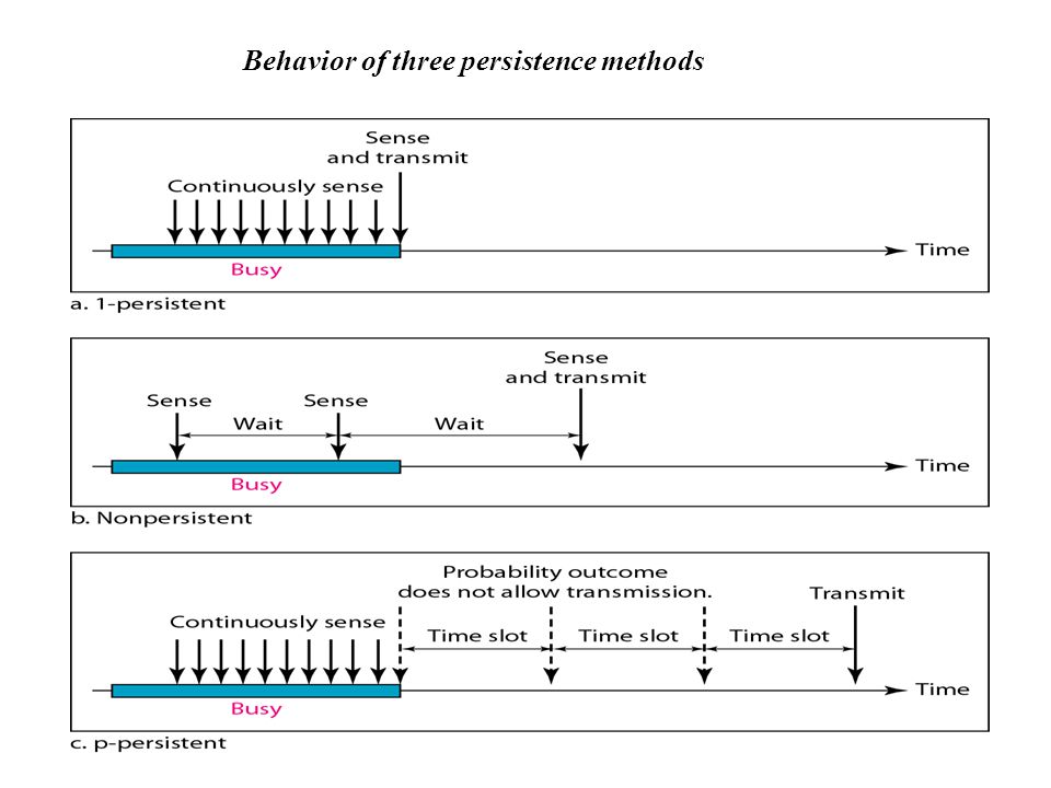
228
Comparison of the channel utilization versus load for various random access protocols

229
CSMA with Collision Detection
CSMA/CD - used on LANs in the MAC layer. When a station detects a collision, it aborts its txn, waits a random time and then tries again, assuming that no other station has txed in the mean time. Therefore CSMA/CD consists of alternating contention and transmission periods, with idle periods occurring when all stations are quiet. Widely used LANs in MAC sublayer The min time to detect the collision is just the time it takes the signal to propagate from 1 station to another.

230
Consider a worst-case scenario:
Let the time for a signal to propagate betwn the 2 farthest station is τ At t0 one statn begins txing . At τ-ε, an instant before the signal arrives at the most distant statn that statn also begins txing . It detects collision instantly and stops ,but the little noise burst caused by the collision does not get back to the original station until time 2τ – ε Ie, in the worst case a station cannot be sure that it has seized the channel until it has txed for 2τ without hearing a collision . For this reason the contention interval is 2τ where τ is the time for a signal to propagate betwn the 2 farthest station.

232
CSMA/CD can be in one of three states: contention, transmission, or idle.
Collision Detection is an analog process. The stations’ H/W must listen to the cable while it is txing. If what it reads back is different from what it is putting out ,it knows a collision is occurring. Ie, signal encoding must allow collisions to be detected. Eg: collision of two 0-volt signal is impossible to detect For this special encoding schemes are used

233
COLLISION-FREE PROTOCOLS
Some protocols that resolve the contention for the channel without any collision at all Bit map protocol - Each contention period consists of exactly N slots. Working: If station 0 has a frame to send ,it transmits a 1 bit during the zeroth slot. No other station is allowed to transmit during this slot. Same manner station 1 also get chance to transmit a 1bit during slot 1,but only if it has a frame queued. i.e, station j may announce the fact that it has a frame to send by inserting a 1 bit into slot . After all N slots have passed by ,each station has complete knowledge of which station wish to transmit. At that point they begin txing in numerical order.

234
The basic bit-map protocol
Since everyone agrees on who goes next, there will never be any collisions. After the last ready statn has txed its frame ,an event all stations can easily monitor , another N bit contention period is begun. If a statn becomes ready just after its bit slot has passed by ,it remain silent until every statn has had a chance and the bit map has come around again. Protocol in which the desire to transmit is broadcast before the actual txn are called Reservation protocols

235
Binary Countdown – Main disadv of bit-map protocol is overhead of 1 bit/stn A statn wanting to use the channel now broadcasts its address as a binary bit string. All addresses are assumed to be the same length. The bits in each address positions from different statns are BOOLEAN ORed together. To avoid conflicts an arbitration rule must be applied. As soon as a station sees that a high-order bit position that is 0 in its address has been overwritten with a 1 ,it gives up. Eg: If stations 0010,0100,1001,1010,are all trying to get the channel ,in the first bit time the statn transmit 0,0,1,1 respectively. These are ORed together to form a 1.

236
The binary countdown protocol. A dash indicates silence.

237
Next bit is 0 and both statns continue.
Station 0010 and 0100 see the 1 and know that a higher-numbered statn is competing for the channel so the give up for the current round. Stations 1001 and 1010 continue. Next bit is 0 and both statns continue. The next bit is 1 so station 1001 gives up. Winner is statn 1010 ,bcos it has the highest address. After winning the bidding ,it may now transmit a frame after which another bidding cycle starts..

238
Limited-Contention Protocols
Combining best properties of the contention and collision-free protocols Uses contention at low load to provide low delay, & collision-free technique at high load to provide good channel efficiency. Such protocols which are called limited-contention protocols Limited Contention Protocol: Divide stn into groups If one succeeds it acquires channel & transmits frame Slot vacant or idle channel - group1 contents for slot1 Assigning stations into slots Each grp has only 1 member Assigning 2 stn per group Way to assign stns to slots dynamically with many stns/slot at low load & few stns/slot at high load

239
Adaptive Tree walk Protocol
Stns as leaves of binary tree If collision occur during slot 0 ,DFS to locate all ready stns When load is high-method inefficient Improvements on basic algorithm is made

240
Wavelength Division Multiple Access Protocols
Divide the channel into sub channels using FDM,TDM or both and dynamically allocate them Commonly used on fiber optic LANs to permit diff conversations to use diff wavelengths at same time To allow multiple transmissions at same time spectrum divided into channels Each stn assigned 2 channels Narrow channel:-ctrl channel to signal stns Wide channel:-to output data frames All channels synchronized by single common clock Supports 3 types of traffic Constant data rate connection-oriented traffic:-uncompressed video Variable data rate connection-oriented traffic:-file transfer Datagram traffic:-UDP packets

241
Each stns has 2 transmitters & 2 receivers
Fixed wavelength receiver :-listening own ctrl channel Tunable transmitter:-sending on other stns ctrl channel Fixed wavelength transmitter:-outputting data frames Tunable receiver:-selecting a data transmitter to listen to

242
Wireless LAN Protocols IEEE 802.11
A system of portable computers that communicate by radio can be regarded as a wireless LAN. It is possible to use CSMA in wireless LAN: just listen to others txn and only transmit if no one else is doing so. Problems: The radio range is such that A and B are within each others range and can potentially interfere with one another. From fig a: if C senses the medium it wont hear A because A is out of range and thus falsely conclude that A can transmit. If C starts it will interfere at B, wiping out the frame from A.

243
If C starts it will interfere at B, wiping out the frame from A.
Problems: The radio range is such that A and B are within each others range and can potentially interfere with one another. From fig a: if C senses the medium it wont hear A because A is out of range and thus falsely conclude that A can transmit. If C starts it will interfere at B, wiping out the frame from A. Hidden station problem:-pblm of a stn not being able to detect a potential competitor for medium because competitor is too far away Consider B transmitting to A (fig b). C senses medium hears an ongoing transmission and falsely conclude that it may not send to D Whereas such a transmission cause bad reception only between B & C, where neither of intended receivers is located. This situation is called as Exposed station problem
. C senses medium hears an ongoing transmission and falsely conclude that it may not send to D. Whereas such a transmission cause bad reception only between B & C, where neither of intended receivers is located. This situation is called as Exposed station problem.")
244
MACA (Multiple Access with Collision Avoidance)
Basis for IEEE wireless LAN std Basic idea is for the sender to stimulate the rxer into o/ping a short frame, so stations nearby can detect this txn and avoid txing themselves for the duration of the upcoming data frame. Idea: A sends an RTS (Request To Send) frame to B. This short frame(30 byte) contains the length of the data frame that will follow. Then B replies with a CTS (Clear To Send). This contains the data Length copied from the RTS. Upon receipt of the CTS frame A begins txn. Logic: Any statn hearing RTS is clearly close to A and must remain silent long enough for the CTS to b txed back to A without conflict. Any statn hearing CTS is near to B and must remain silent during the upcoming data txn-whose length it can tell by examining the CTS frmae.
 frame to B. This short frame(30 byte) contains the length of the data frame that will follow. Then B replies with a CTS (Clear To Send). This contains the data Length copied from the RTS. Upon receipt of the CTS frame A begins txn. Logic: Any statn hearing RTS is clearly close to A and must remain silent long enough for the CTS to b txed back to A without conflict. Any statn hearing CTS is near to B and must remain silent during the upcoming data txn-whose length it can tell by examining the CTS frmae.")
245
(a) A sending an RTS to B. (b) B responding with a CTS to A.
The MACA protocol. (a) A sending an RTS to B. (b) B responding with a CTS to A.
 A sending an RTS to B. (b) B responding with a CTS to A.")
246
Despite these precautions, collisions can still occur.
For eg, B and C could both send RTS frames to A at the same time. These will collide and be lost. In the event of a collision, an unsuccessful transmitter does not hear a CTS within the expected time interval) waits a random amount of time and tries again later. The algorithm used is binary exponential backoff without dll acks, lost frames were not retransmitted until the transport layer noticed their absence MACAW Based on simulation studies MACA was fine tuned to improve its performance & renamed MACAW (MACA for Wireless). solved the pblm of lost frames by introducing an ACK frame after each successful data frame. they decided to run the backoff algorithm separately for each data stream (source-destination pair), rather than for each station. This change improves the fairness of the protocol. added a mechanism for stations to exchange information about congestion and a way to make the backoff algorithm react less violently to temporary problems, to improve system performance.
 waits a random amount of time and tries again later. The algorithm used is binary exponential backoff. without dll acks, lost frames were not retransmitted until the transport layer noticed their absence. MACAW. Based on simulation studies MACA was fine tuned to improve its performance & renamed MACAW (MACA for Wireless). solved the pblm of lost frames by introducing an ACK frame after each successful data frame. they decided to run the backoff algorithm separately for each data stream (source-destination pair), rather than for each station. This change improves the fairness of the protocol. added a mechanism for stations to exchange information about congestion and a way to make the backoff algorithm react less violently to temporary problems, to improve system performance.")
247
IEEE Standard 802 For LANs and MANs

248
802.1 std:-introduction to set of stds & defines interface primitives
IEEE has standardized a number of local area networks and metropolitan area networks under the name of IEEE 802 802.1 std:-introduction to set of stds & defines interface primitives 802.2 std:-describes upper part of data link layer which uses LLC (Logical Link Control) protocol 3 LAN stds 802.3 std:-CSMA/CD 802.4 std:-token bus 802.5 std:-token ring 802.6 std:-DQDB (Distributed Queue Dual Bus) Standards differ at the physical layer, but are compatible at the data-link layer
 protocol. 3 LAN stds std:-CSMA/CD std:-token bus std:-token ring std:-DQDB (Distributed Queue Dual Bus) Standards differ at the physical layer, but are compatible at the data-link layer.")
249
IEEE STANDARD 802.3: ETHERNET
This is for a 1-persistent CSMA/CD LAN. This s/m was called Ethernet after the lumiferous ether through which EM radiation was once thought to propagate. Xerox, Intel and DEC made a standard for a 10-Mbps Ethernet. This std formed the basis for 802.3 CABLING

250
IEEE STANDARD 802.3: ETHERNET
10Base5: thick Ethernet . 10Base5means it operates at 10Mbps,uses base band signaling, and can support segments up to 500 Meters. Resembles a yellow garden hose with marking every 205 Ms to show where the taps go. Connections t it are made using vampire taps in which a pin is carefully forced halfway in to the coaxial cables core. 10Base2: thin Ethernet. Bends easily. Connections are made using std BNC connector to form T junction. Easier to use and more reliable. Much cheaper and easy to install But it can run for only 200m ,and can handle only 30 m/cs per cable segment. 10BaseT: For finding cable breaks all stations have a cable running to the central hub. These wires are telephone company twisted pairs. These scheme is called 10BaseT Hubs are costly Max cable length from hub is only 100m Popular due to ease of maintanence

251
Expensive due to cost of connectors & terminators
10BaseF: Uses fiber optics Expensive due to cost of connectors & terminators It has excellent noise immunity

252
For large n/ws, multiple cables can be connected by repeaters
Cable topologies a) Linear b) Spine c) Tree d) Segmented For large n/ws, multiple cables can be connected by repeaters Repeater is a physical layer device. It receives, amplifies and retransmits signals in both directions
 Linear b) Spine c) Tree d) Segmented. For large n/ws, multiple cables can be connected by repeaters. Repeater is a physical layer device. It receives, amplifies and retransmits signals in both directions.")
253
Manchester Encoding Straight binary encoding with 0 volts for a 0 bit
Leads to ambiguities Two such approaches are called Manchester encoding and differential Manchester encoding. With Manchester Encoding each bit period is divided into 2 equal intervals. A binary 1 bit is sent by having the voltage set high during the first interval and low in the second. A binary 0 is its reverse: first low and then high. This scheme ensures that every bit period has a transition in the middle ,making it easy for the rxer to synchronize with the sender. Disadvtg: it requires twice as much b/w as straight binary encoding becos the pulses are half the width.

254
In both cases there is a transition in the middle as well.
In Differential ME a 1 bit is indicated by the absence of transition at the start of the interval. A 0 bit is indicated by the presence of a transition at the start of the interval. In both cases there is a transition in the middle as well. It has better noise immunity.

255
802.3 MAC Sublayer Protocol Packet Definition

256
Start of frame :10101011 to denote the start of a frame
Preamble :of 7 bytes (this produces a square wave of 10MHz for 5.6 microSec to allow the rxer’s clock to synchronize with the sender.) Start of frame : to denote the start of a frame Destn/Source Address: supports 2/6 bytes(10Mbps std uses 6 –byte adrs) High order bit is 0 for ordinary adrs and 1 for group address. When a frame is sent to a group address all the statns in the group receive it (multicast) The address consisting of all 1 bits is reserved for broadcast Frame containing all 1s in the destn field is delivered to all stations on the n/w. Length: tells how many bytes are present in the data field ( 0 to a max of 1500) A valid frame must be at least 64 bytes long from destn adrs to check sum. If the data portion of the frame is less than 46 bytes the pad field is used to fill out the frame to min size. Checksum: is a 32-bit hash code of the data .The check sum algorithm is a CRC type.
 Start of frame : to denote the start of a frame. Destn/Source Address: supports 2/6 bytes(10Mbps std uses 6 –byte adrs) High order bit is 0 for ordinary adrs and 1 for group address. When a frame is sent to a group address all the statns in the group receive it (multicast) The address consisting of all 1 bits is reserved for broadcast. Frame containing all 1s in the destn field is delivered to all stations on the n/w. Length: tells how many bytes are present in the data field ( 0 to a max of 1500) A valid frame must be at least 64 bytes long from destn adrs to check sum. If the data portion of the frame is less than 46 bytes the pad field is used to fill out the frame to min size. Checksum: is a 32-bit hash code of the data .The check sum algorithm is a CRC type.")
257
Manchester Encoding In Differential ME a 1 bit is indicated by the absence of transition at the start of the interval. A 0 bit is indicated by the presence of a transition at the start of the interval. In both cases there is a transition in the middle as well. It has better noise immunity.

258
IEEE STANDARD 802.4: TOKEN BUS
Drawbacks of 802.3: Station have to wait long to send frame Frames do not have priorities. Token Bus Need a mechanism to handle real-time, deterministic requirements. A ring, with stations take turns in sending frames. Uses logical ring on linear cable. It is linear or tree-shaped cable onto which the stations r attached. Mechanism: Logically stations are organized into ring with each station knowing the address of the station to its LEFT and RIGHT. When the ring is initialized the highest numbered station may send the first frame. Then it passes permission to its immediate neighbor by sending a special control frame called token The token propagates around the logical ring with only the token holder being permitted to transmit frames. Since only 1 station at a time holds the token collisions do not occur.

259
Token Bus Local ring 17 14 20 Broad band coaxial cable 13 11 7 19 This station not currently in the logical ring Direction of token motion

260
Physical layer: uses 75 ohm broadband coaxial cable (cable TV).
Physical order in which stations are connected to the cable is not important. Each station receives each frame discarding the ones not addressed to it When a station passes the token ,it sends the token frame specifically addressed to its logical neighbor in the ring, irrespective of its physical location on the cable. When the stations are first powered on they will not be in the ring , so the MAC protocol has provisions for adding stations to and deleting stations from the ring. Very complex protocol with each station having to maintain 10 diff timers and 2 dozen internal variables States are reprersented as finite state machines and actions written in Ada Physical layer: uses 75 ohm broadband coaxial cable (cable TV).
.")
261
IEEE STANDARD 802.4: TOKEN BUS
TOKEN BUS MAC SUBLAYER PROTOCOL: When ring is initialized ,stations are inserted in in order of statn address from highest to lowest. Token passing is also from high to low address. When a station acquires a token it can transmit frames for a certain amount of time. Then it must pass the token on If frames are short enough several consecutive frames may sent. If a station has no data it passes the token immediately upon rxing it. Station has 4 possible priorities, 0, 2, 4, 6( 0 lowest and 6 highest) Ie, each station internally being divided into 4 substations, one at each priority level As i/p comes in to the MAC sub layer the data are checked for priority and routed to one of the four substations Thus each substatn maintains its own queue of frames to be txed.
 Ie, each station internally being divided into 4 substations, one at each priority level. As i/p comes in to the MAC sub layer the data are checked for priority and routed to one of the four substations. Thus each substatn maintains its own queue of frames to be txed.")
262
When the token comes into the station thru cable, it is passed internally to the priority 6 substation, which begin txing first if it has any. When it is done (or timer expires) the token is passed internally to the priority 4 substn and this process continues until priority 0 substation sent all its frame. Proper setting of the various timers ensures that high priority requests happen first.
 the token is passed internally to the priority 4 substn and this process continues until priority 0 substation sent all its frame. Proper setting of the various timers ensures that high priority requests happen first.")
263
802.4 frame format

264
Preamble : to synchronize with the sender
Starting and Ending delimiter : mark boundaries ,so no length field reqd Frame control : distinguish data from ctrl frames. It carries frame priority for data frame Destn/Source Address: supports 2/6 bytes(10Mbps std uses 6 –byte adrs) High order bit is 0 for ordinary adrs and 1 for group address. When a frame is sent to a group address all the statns in the group receive it (multicast) The address consisting of all 1 bits is reserved for broadcast Frame containing all 1s in the destn field is delivered to all stations on the n/w. Data :up to 8182 bytes long Checksum: is a 32-bit hash code of the data .The check sum algorithm is a CRC type.
 High order bit is 0 for ordinary adrs and 1 for group address. When a frame is sent to a group address all the statns in the group receive it (multicast) The address consisting of all 1 bits is reserved for broadcast. Frame containing all 1s in the destn field is delivered to all stations on the n/w. Data :up to 8182 bytes long. Checksum: is a 32-bit hash code of the data .The check sum algorithm is a CRC type.")
265
IEEE STANDARD 802.5: TOKEN RING
Wire Center Logically still ring but physically each station is connected to the wire center by a cable containing (at least) 2 TPs, one for data to the station and one for data from the station. Inside the wire center are bypass relays that are energized by current from the station. If the ring breaks or a station goes down , loss of the drive current will release the relay and bypass the station
 2 TPs, one for data to the station and one for data from the station. Inside the wire center are bypass relays that are energized by current from the station. If the ring breaks or a station goes down , loss of the drive current will release the relay and bypass the station.")
266
TOKEN RING MAC SUBLAYER PROTOCOL
When there is no traffic on the ring, a 3-byte token circulates endlessly waiting for a station to seize it by setting a specific 0 bit to a 1 bit ,thus converting the token into the start-of-frame sequence. then station o/ps the rest of the normal data frames.

267
Frame Structure Components -
SD, ED : Delimiters - have invalid DME(HH and LL) so not confused as data. AC : Access control, containing bits for: The token bit Monitor bit, Priority bits, Reservation bits FC: Frame control Provides numerous control options. Source/Destination addresses/checksum same as &
 so not confused as data. AC : Access control, containing bits for: The token bit. Monitor bit, Priority bits, Reservation bits. FC: Frame control Provides numerous control options. Source/Destination addresses/checksum. same as &")
268
Frame Structure Components –
FS: Frame status: Contains A and C bit When a frame arrives at the i/f of a station with the destn adrs ,the i/f turns on the A bit as it passes through. If the i/f copies the frame to the station ,it also turns on the C bit. When the sending stn drains the frame from the ring ,it examines the A and C bits . 3 combinations r possible: 1.A=0 and C=0:destn not present or powered up. 2.A=1 and C=0:destn present but frame not copied 3.A=1 and C=1:destn present and frame copied Serves as an automatic acknowledgment for each frame.. Priorities - 802.5 has an elaborate scheme for handling multiple priority. The 3-byte token frame contains a field in the middle byte giving the token priority

269
Garbled frame - Monitor drains the frame and issues new token.
RING MAINTENANCE: Monitor station oversees the ring, but on failure any station can become monitor. CLAIM_TOKEN is a request to become the new monitor. Monitor oversees: Lost token management - If timer says token not seen in a while, produce new one. Orphan frames - Frame on ring, but sender crashes before draining frame Garbled frame - Monitor drains the frame and issues new token. Delay time - Ensures enough delay so whole token fits on ring.

270
COMPARISONS OF 802.3, 802.4, AND 802.5:

271
IEEE Standard 802 For LANs and MANs
272
802.1 std:-introduction to set of stds & defines interface primitives
IEEE has standardized a number of local area networks and metropolitan area networks under the name of IEEE 802 802.1 std:-introduction to set of stds & defines interface primitives 802.2 std:-describes upper part of data link layer which uses LLC (Logical Link Control) protocol 3 LAN stds 802.3 std:-CSMA/CD 802.4 std:-token bus 802.5 std:-token ring 802.6 std:-DQDB (Distributed Queue Dual Bus) Standards differ at the physical layer, but are compatible at the data-link layer
 protocol. 3 LAN stds std:-CSMA/CD std:-token bus std:-token ring std:-DQDB (Distributed Queue Dual Bus) Standards differ at the physical layer, but are compatible at the data-link layer.")
273
IEEE STANDARD 802.3: ETHERNET
This is for a 1-persistent CSMA/CD LAN. This system was called Ethernet after the lumiferous ether through which EM radiation was once thought to propagate. Xerox, Intel and DEC made a standard for a 10-Mbps Ethernet. This std formed the basis for 802.3 CABLING

274
IEEE STANDARD 802.3: ETHERNET
10Base5: thick Ethernet . 10Base5means it operates at 10Mbps,uses base band signaling, and can support segments up to 500 Meters. Resembles a yellow garden hose with marking every 205 Ms to show where the taps go. Connections t it are made using vampire taps in which a pin is carefully forced halfway in to the coaxial cables core. 10Base2: thin Ethernet. Bends easily. Connections are made using std BNC connector to form T junction. Easier to use and more reliable. Much cheaper and easy to install But it can run for only 200m ,and can handle only 30 m/cs per cable segment. 10BaseT: For finding cable breaks all stations have a cable running to the central hub. These wires are telephone company twisted pairs. These scheme is called 10BaseT Hubs are costly Max cable length from hub is only 100m Popular due to ease of maintanence

275
Expensive due to cost of connectors & terminators
10BaseF: Uses fiber optics Expensive due to cost of connectors & terminators It has excellent noise immunity

276
For large n/ws, multiple cables can be connected by repeaters
Cable topologies a) Linear b) Spine c) Tree d) Segmented For large n/ws, multiple cables can be connected by repeaters Repeater is a physical layer device. It receives, amplifies and retransmits signals in both directions
 Linear b) Spine c) Tree d) Segmented. For large n/ws, multiple cables can be connected by repeaters. Repeater is a physical layer device. It receives, amplifies and retransmits signals in both directions.")
277
Manchester Encoding Straight binary encoding with 0 volts for a 0 bit
Leads to ambiguities Two such approaches are called Manchester encoding and differential Manchester encoding. With Manchester Encoding each bit period is divided into 2 equal intervals. A binary 1 bit is sent by having the voltage set high during the first interval and low in the second. A binary 0 is its reverse: first low and then high. This scheme ensures that every bit period has a transition in the middle ,making it easy for the rxer to synchronize with the sender. Disadvtg: it requires twice as much b/w as straight binary encoding because the pulses are half the width.

278
Manchester Encoding In Differential ME a 1 bit is indicated by the absence of transition at the start of the interval. A 0 bit is indicated by the presence of a transition at the start of the interval. In both cases there is a transition in the middle as well. It has better noise immunity.. 802.3 baseband systems use Manchester encoding

279
802.3 MAC Sublayer Protocol Packet Definition

280
Start of frame :10101011 to denote the start of a frame
Preamble :of 7 bytes (this produces a square wave of 10MHz for 5.6 microSec to allow the rxer’s clock to synchronize with the sender.) Start of frame : to denote the start of a frame Destn/Source Address: supports 2/6 bytes(10Mbps std uses 6 –byte adrs) High order bit is 0 for ordinary adrs and 1 for group address. When a frame is sent to a group address all the statns in the group receive it (multicast) The address consisting of all 1 bits is reserved for broadcast Frame containing all 1s in the destn field is delivered to all stations on the n/w. Length: tells how many bytes are present in the data field ( 0 to a max of 1500) A valid frame must be at least 64 bytes long from destn adrs to check sum. If the data portion of the frame is less than 46 bytes the pad field is used to fill out the frame to min size. Checksum: is a 32-bit hash code of the data .The check sum algorithm is a CRC type.
 Start of frame : to denote the start of a frame. Destn/Source Address: supports 2/6 bytes(10Mbps std uses 6 –byte adrs) High order bit is 0 for ordinary adrs and 1 for group address. When a frame is sent to a group address all the statns in the group receive it (multicast) The address consisting of all 1 bits is reserved for broadcast. Frame containing all 1s in the destn field is delivered to all stations on the n/w. Length: tells how many bytes are present in the data field ( 0 to a max of 1500) A valid frame must be at least 64 bytes long from destn adrs to check sum. If the data portion of the frame is less than 46 bytes the pad field is used to fill out the frame to min size. Checksum: is a 32-bit hash code of the data .The check sum algorithm is a CRC type.")
281
Packet Definition Preamble == 7 bytes of 10101010
Start == 1 byte of Dest == 6 bytes of MAC address multicast == sending to a group of stations. broadcast== (dest = all 1's) to all stations on network Source == 6 bytes of MAC address Length == number of bytes of data Data == comes down from network layer Pad == ensures 64 bytes from dest addr thru checksum. checksum == 4 bytes of CRC.
 to all stations on network. Source == 6 bytes of MAC address. Length == number of bytes of data. Data == comes down from network layer. Pad == ensures 64 bytes from dest addr thru checksum. checksum == 4 bytes of CRC.")
282
IEEE STANDARD 802.4: TOKEN BUS
Drawbacks of 802.3: Station have to wait long to send frame Frames do not have priorities. Token Bus Need a mechanism to handle real-time, deterministic requirements. A ring, with stations take turns in sending frames. Uses logical ring on linear cable. It is linear or tree-shaped cable onto which the stations are attached. Mechanism: Logically stations are organized into ring with each station knowing the address of the station to its LEFT and RIGHT. When the ring is initialized the highest numbered station may send the first frame. Then it passes permission to its immediate neighbor by sending a special control frame called token The token propagates around the logical ring with only the token holder being permitted to transmit frames. Since only 1 station at a time holds the token collisions do not occur.

283
Token Bus Local ring 17 14 20 Broad band coaxial cable 13 11 7 19 This station not currently in the logical ring Direction of token motion

284
Physical layer: uses 75 ohm broadband coaxial cable (cable TV).
Physical order in which stations are connected to the cable is not important. Each station receives each frame discarding the ones not addressed to it When a station passes the token ,it sends the token frame specifically addressed to its logical neighbor in the ring, irrespective of its physical location on the cable. When the stations are first powered on they will not be in the ring , so the MAC protocol has provisions for adding stations to and deleting stations from the ring. Very complex protocol with each station having to maintain 10 diff timers and 2 dozen internal variables States are represented as finite state machines and actions written in Ada Physical layer: uses 75 ohm broadband coaxial cable (cable TV).
.")
285
IEEE STANDARD 802.4: TOKEN BUS
TOKEN BUS MAC SUBLAYER PROTOCOL: When ring is initialized ,stations are inserted in order of statn address from highest to lowest. Token passing is also from high to low address. When a station acquires a token it can transmit frames for a certain amount of time. Then it must pass the token on If frames are short enough several consecutive frames may sent. If a station has no data it passes the token immediately upon receiving it. It has 4 priority classes: 0, 2, 4, 6( 0 lowest and 6 highest) Ie, each station internally being divided into 4 substations, one at each priority level As i/p comes in to the MAC sub layer the data are checked for priority and routed to one of the four substations Thus each substatn maintains its own queue of frames to be txed.
 Ie, each station internally being divided into 4 substations, one at each priority level. As i/p comes in to the MAC sub layer the data are checked for priority and routed to one of the four substations. Thus each substatn maintains its own queue of frames to be txed.")
286
Lower priorities have to live with what is left over
When the token comes into the station thru cable, it is passed internally to the priority 6 substation, which begin txing first if it has any. When it is done (or timer expires) the token is passed internally to the priority 4 substn and this process continues until priority 0 substation sent all its frame or its timer has expired Proper setting of the various timers ensures that high priority requests happen first. Lower priorities have to live with what is left over If higher priority stns does not need all allocated time then lower priority stns can use them, so it is not wasted This priority scheme which guarantees priority 6 traffic used to implement real-time traffic
 the token is passed internally to the priority 4 substn and this process continues until priority 0 substation sent all its frame or its timer has expired. Proper setting of the various timers ensures that high priority requests happen first. Lower priorities have to live with what is left over. If higher priority stns does not need all allocated time then lower priority stns can use them, so it is not wasted. This priority scheme which guarantees priority 6 traffic used to implement real-time traffic.")
287
802.4 frame format

288
Preamble : to synchronize with the sender
Starting and Ending delimiter : mark boundaries, uses analog encoding of symbols other than 0s and 1s No length field reqd Frame control : distinguish data from ctrl frames. It carries frame priority for data frame Destn/Source Address: supports 2/6 bytes(10Mbps std uses 6 –byte adrs) High order bit is 0 for ordinary adrs and 1 for group address. When a frame is sent to a group address all the statns in the group receive it (multicast) The address consisting of all 1 bits is reserved for broadcast Frame containing all 1s in the destn field is delivered to all stations on the n/w. Data :up to 8182 bytes(2-byte addressing) long and 8174 bytes(6-byte addresses) Checksum: is a 32-bit hash code of the data .The check sum algorithm is a CRC type.
 High order bit is 0 for ordinary adrs and 1 for group address. When a frame is sent to a group address all the statns in the group receive it (multicast) The address consisting of all 1 bits is reserved for broadcast. Frame containing all 1s in the destn field is delivered to all stations on the n/w. Data :up to 8182 bytes(2-byte addressing) long and 8174 bytes(6-byte addresses) Checksum: is a 32-bit hash code of the data .The check sum algorithm is a CRC type.")
289
Logical Ring Maintenance
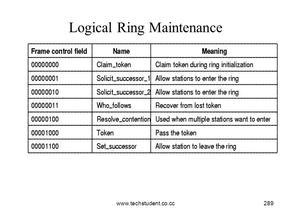
290
2. RESOLVE_CONTENTION frame-this frame is broadcasted to n/w
SOLICIT_SUCCESSOR frames-solicits bids from stns that wish to join ring Frame sends senders addr & successors addr If no stn responds within slot time, response window is closed & token holder continues with its normal opns If only 1 stn responds, it is inserted and becomes token holders successor If more than 1 stn responds simultaneously then collision occurs. Token holder then runs arbitration algorithm with broadcast of RESOLVE_CONTENTION frame 2. RESOLVE_CONTENTION frame-this frame is broadcasted to n/w 3. SET_SUCCESSOR frame-to leave the ring Eg: stn X with successor S and predecessor P X generates SET_SUCCESSOR frame and sends it to P informing that now onwards S is its successor instead of X 4. CLAIM_TOKEN frame- used for ring initialization and adding new stns 1st stn in ring generates this frame It creates a token & sets up the ring containing only itself. Then it solicits bids for new stns

291
Problems with logical ring or token
Stn tries to pass token to stn that has gone down After passing the token stn listens to see if its successor either transmits frame or passes the token If it does neither it tries 2nd time If that also fails stn transmits WHO_FOLLOWS frame specifying address of its successor When failed stns successor sees WHO_FOLLOWS frame naming its predecessor, it sends SET_SUCCESSOR frame announcing itself as new successor Token holder goes down taking token with it Solved using ring intialization algo Each stn has timer that is reset when frame appears on n/w Multiple tokens Stn holding token notices a transmission from another stn, it discards its token

292
IEEE STANDARD 802.5: TOKEN RING
Wire Center Logically still ring but physically each station is connected to the wire center by a cable containing (at least) 2 TPs, one for data to the station and one for data from the station. Inside the wire center are bypass relays that are energized by current from the station. If the ring breaks or a station goes down , loss of the drive current will release the relay and bypass the station
 2 TPs, one for data to the station and one for data from the station. Inside the wire center are bypass relays that are energized by current from the station. If the ring breaks or a station goes down , loss of the drive current will release the relay and bypass the station.")
293
TOKEN RING MAC SUBLAYER PROTOCOL
When there is no traffic on the ring, a 3-byte token circulates endlessly waiting for a station to seize it by setting a specific 0 bit to a 1 bit ,thus converting the token into the start-of-frame sequence. then station o/ps the rest of the normal data frames.

294
Frame Structure Components -
SD, ED : Delimiters - have invalid DME(HH and LL) so not confused as data. AC : Access control, containing bits for: The token bit Monitor bit, Priority bits, Reservation bits FC: Frame control Provides numerous control options. Source/Destination addresses/checksum same as &
 so not confused as data. AC : Access control, containing bits for: The token bit. Monitor bit, Priority bits, Reservation bits. FC: Frame control Provides numerous control options. Source/Destination addresses/checksum. same as &")
295
Frame Structure Components –
FS: Frame status: Contains A and C bit When a frame arrives at the i/f of a station with the destn adrs ,the i/f turns on the A bit as it passes through. If the i/f copies the frame to the station ,it also turns on the C bit. When the sending stn drains the frame from the ring ,it examines the A and C bits . 3 combinations r possible: 1.A=0 and C=0:destn not present or powered up. 2.A=1 and C=0:destn present but frame not copied 3.A=1 and C=1:destn present and frame copied Serves as an automatic acknowledgment for each frame.. Priorities - 802.5 has an elaborate scheme for handling multiple priority. The 3-byte token frame contains a field in the middle byte giving the token priority

296
Garbled frame - Monitor drains the frame and issues new token.
RING MAINTENANCE: Monitor station oversees the ring, but on failure any station can become monitor. CLAIM_TOKEN is a request to become the new monitor. Monitor oversees: Lost token management - If timer says token not seen in a while, produce new one. Orphan frames - Frame on ring, but sender crashes before draining frame Garbled frame - Monitor drains the frame and issues new token. Delay time - Ensures enough delay so whole token fits on ring.

297
COMPARISONS OF 802.3, 802.4, AND 802.5:

Similar presentations
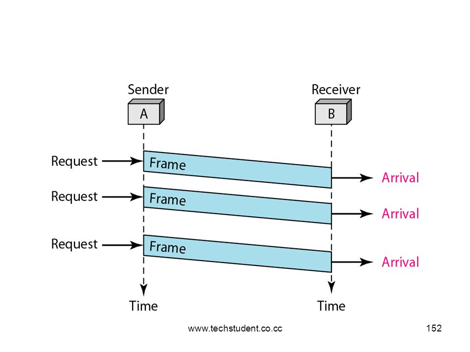


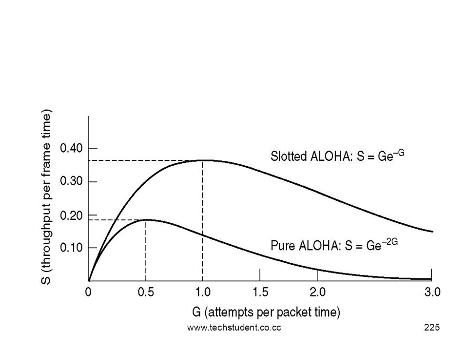


. Data Link Protocols The set of specifications used to implement the DLL. DLL Protocols Synchronous Protocols Character-oriented.>")


 ALOHA Slotted ALOHA CSMA CSMA/CD Token Ring /FDDI Fiber Channel Fiber Channel Protocol.>")


