Download presentation
Presentation is loading. Please wait.

1
Design of an Enhanced FOD Inspection System for the Aircraft Production Process
Manual Inspection Enhanced Inspection Manual Inspection Enhanced Inspection Foreign Object Debris (FOD) By: Justin Amoyal, Roman Garber, Marwan Karama, Meba Kassahun & Anoosha Koohi
 By: Justin Amoyal, Roman Garber, Marwan Karama, Meba Kassahun & Anoosha Koohi.")
2
Agenda Context Stakeholder Analysis & CONOPS
Fighter Jet Production Overview FOD Overview Current FOD Prevention Process Stakeholder Analysis & CONOPS Approach & System Alternatives Methods & Models Project Management Future Steps

3
Fighter Jet Introduction
_______ F-117 _______ F-22 F-35 Flyaway cost is one measure of the cost of an aircraft. It values the aircraft at its marginal cost, including only the cost of production and production tools essential for building a single unit. It excludes prior costs such as research and development (treating these as sunk costs), supplementary costs such as support equipment, or future costs such as spares and maintenance
, supplementary costs such as support equipment, or future costs such as spares and maintenance.")
4
Case Model – Lockheed Martin F-35

6
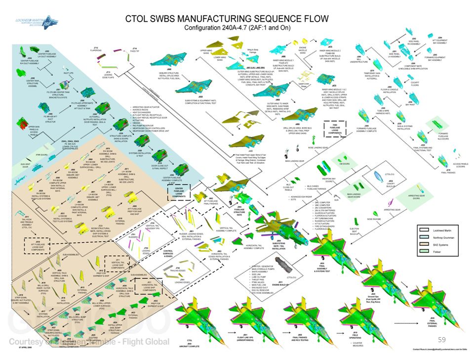
F-35 Production Flow

7
FOD Overview Foreign Object Debris (FOD): A substance, debris or article alien to a vehicle or system which would potentially cause damage. According to Boeing, FOD costs the aerospace industry $4 Billion/year Classification Examples Panstock Washer, Bolt, Screw, Pin Consumables Rag, Cap, Bag, Bottle Personal Items Pens, Key, Change, Paper Tools/Shop Aids Wrench, Socket, Hammer Perishables/Expendables Clamps, Drill Bits, Apex Tips Trash Plastic Wrap, Used Tape Manufacturing Debris Metal Shavings, Rivet Tails Environmental Rocks/Pebbles, Insects

8
FOD Affect on Current Fighter Jet Production Process
FOD Arrival Rate Exponential[.183]

9
Current FOD Prevention Technique

10
F35 Production with Manual FOD Inspection

11
Agenda Context Stakeholder Analysis & CONOPS
Gap & Problem Mission Requirements Approach & System Alternatives Methods & Models Project Management Future Steps

12
Title Example Objectives
Class Title Example Objectives Primary Production Line Personnel FOD Inspectors FOD Associations FOD Inspection Training Personnel 1a. Mechanic/Engineer involved in inspecting/detecting FOD 1b. Mechanic/Engineer involved in FOD related rework and repair 2a. Personnel Scanning for FOD 2b. Personnel documenting instance's of FOD 3a. National Aerospace FOD Prevention Inc. 4a. Personnel responsible for FOD certification/training 1a. Limit FOD inputted 1a.Detect any FOD present 1b. Remove FOD present 1b. Repair Aircraft Component 2a. Detect FOD 2b. Document FOD occurrence 3a. Standardize terms & methods for the prevention of FOD to A/C 4a. Teach FOD prevention to employees Secondary Aircraft Production Corporation Aircraft Customers Aircraft Pilots 1a. Lockheed Martin 2a. 3 US Government Branches 2b. International F35 Customers 3a. Marine Pilot 1a. Eliminate FOD present during Customer Delivery 1a. Limit rework and repair time 1a.Produce A/C as efficiently/quick as possible 2a/2b. Pilot Safety 2a/2b. Advanced AC capabilities 2a/2b. AC delivery in timely manner 3a. Complete mission safely 3a. Test A/C capabilities Tertiary Aircraft Production Stockholders Insurance Companies US Government Foreign Governments 1a. Employees of LMCO with stock & citizens with stock in LMCO 2a. FOD related personnel insurance companies 3a. Department of Defense (DOD) – those in charge of government spending/budgets 4a. Foreign Government contract/budget officials 1a. Maximize Profit 2a. Insure/protect those who may be threatened/affected by FOD 3a. Lowest price for most capable A/C 4a. Most safety with the least amount of FOD
 – those in charge of government spending/budgets. 4a. Foreign Government contract/budget officials. 1a. Maximize Profit. 2a. Insure/protect those who may be threatened/affected by FOD. 3a. Lowest price for most capable. A/C. 4a. Most safety with the least amount of FOD.")
13
Stakeholder Wins & Tensions

14
Problem & Need

15
Gap Analysis Non-Linear relationship between the time to detect FOD and the costs associated Fighter Jet Production is growing, yet FOD Inspection techniques have remained Manual FOD damage is estimated to cost the Aerospace Industry $4 billion a year Complexity Years

16
Enhanced Inspection System Requirements
Requirement Description MR.1.0 System shall have a 98% FOD detection rate in all portions of the Aircraft MR.2.0 System shall support a production rate of 1 plane/day MR.3.0 On-site support shall be provided for 2 weeks per installation location during initial operational phase of equipment. MR.4.0 Supplier shall provide 1 week of operator training for 10 operators MR.5.0 System shall have an ROI of 25% based on LM data sample acquired before the integration of the system and data sample acquired approximately 12 months after system integration MR.6.0 System shall reduce FOD inspection times by 50% based on LM data sample acquired before the integration of the system and data sample acquired approximately 12 months after system integration. MR.7.0 Supplier shall develop an integration plan for incorporation of the equipment into the F-35 production plan. Plan shall be approved by LM 30 days prior to installation.

17
Agenda Context Stakeholder Analysis & CONOPS
Approach & System Alternatives Implementation & Design Alternatives Functional Breakdown Allocated Architecture Imaging Component Analysis Component X-Ray System Alternatives Methods & Models Project Management Future Steps

18
Design Alternatives & Implementation
Manual/Visual Inspection X-Ray imaging & Differential imaging software Automated system with multi-layer view Automated FOD Identification Software 18

19
F35 Production with Enhanced FOD
Inspection

20
External Systems Diagram

21
Functional Architecture

22
Current Problem & Need for a Solution

23
Backscatter & Transmission X-rays
Backscatter X-Rays Both x-ray source and x-ray detectors apparatus are located on one side of the object Transmission X-Rays Passes an X-Ray beam through an object to a detector on the far side

24
X-ray Alternatives X-ray System X-ray System Source
Penetration Power (in steel) Power Requirement Scanning Speed Dimensions Start Up Time Radiation Dose Linear Rail Backscatter 6.3 mm watts 0.185(m^2/s) x 20 min Robotic Arm Gantry Transmission- Optional Backscatter 400 mm 9.6(m^2/s) Length 36.5m Width 3.0m Height 5.0m 15 min 5 mR Z-Portal 300 mm 480 Width 8.9m Height 6.3m MobileSarch Backscatter and Transmission Width 2.5m Height 4.1m 30 min 2 mR Z-Backscatter Van 7.2(m^2/s) Length 7.96 Width2.6m Height 2.9m 10 mSv
 Power Requirement. Scanning Speed. Dimensions. Start Up Time. Radiation Dose. Linear Rail. Backscatter. 6.3 mm watts (m^2/s) x. 20 min. Robotic Arm. Gantry. Transmission- Optional Backscatter. 400 mm (m^2/s) Length 36.5m. Width 3.0m. Height 5.0m. 15 min. 5 mR. Z-Portal. 300 mm Width 8.9m. Height 6.3m. MobileSarch. Backscatter and Transmission. Width 2.5m. Height 4.1m. 30 min. 2 mR. Z-Backscatter Van. 7.2(m^2/s) Length Width2.6m. Height 2.9m. 10 mSv.")
25
Alternatives Per Sub-Assembly

26
Differential Imaging Differential Imaging provides the operator with a means of assistance in identifying the FOD items after the Aircraft Components have been scanned and the images are being compared.

27
Aircraft Sub-Assembly
Center Fuselage Try to identify these two object?

28
Aircraft Sub-Assembly
Center Fuselage

29
Agenda Context Stakeholder Analysis & CONOPS
Approach & System Alternatives Methods & Models Design Of Experiments System Models Inspection Time Model Inspection Reliability Model The Simulation Simulation Inputs & Outputs Variables Assumptions Flow Diagram Business Model Project Management Future Steps

30
Design of Experiments X Ray Alternative Complete Aircraft Instantiated
Generate accurate representation of the F35 production process by gathering data Create Instantiated architectures for the system by deciding which X-Ray alternatives are viable for each Aircraft Sub-Assembly Instantiated architectures will be compared based on cost, rework hours, production time per Aircraft Instantiated Architecture Aircraft Sub-Assembly Total Time Per Aircraft Rework & Repair Hours Station Utilization Total Cost (Installation + Rework & Repair Costs) X Ray Alternative Forward Fuselage Time Value and $ Value Center Fuselage Wing Structure Aft Fuselage X Ray Alternative Complete Aircraft
 X Ray Alternative. Forward Fuselage. Time Value. and. $ Value. Center Fuselage. Wing Structure. Aft. Fuselage. X Ray. Alternative. Complete Aircraft.")
31
Model Interaction

32
Scan Time per Sub-Assembly:
X-ray Inspection Time Model Scan Time per Sub-Assembly: Scan Speed of X-Ray Alternative (V) Surface Area of Sub-Assembly (A) Image Analysis Time (X) 𝑇= 𝐴 𝑉 + X Device Start Up Time Total Inspection Time Per Alternative Total Time
 Surface Area of Sub-Assembly (A) Image Analysis Time (X) 𝑇= 𝐴 𝑉 + X. Device Start Up Time. Total Inspection Time. Per Alternative. Total. Time.")
33
Probability of Detection

34
Probability of Detection Variables
Absorption coefficient (μ) Quantity that characterizes how easily a material can be penetrated by a beam of x-ray. Density ( ρ ) Steel>Titanium> Aluminum X-ray energy Material Density μ Energy μ Half Value Layer (HVL) 50% of x-ray radiation is absorbed P = μ HVL HVL P Inspected component thickness Forward Fuselage AFT fuselage Center fuselage Wing modulus Thickness HVL Thickness Penetration
 Quantity that characterizes how easily a material can be penetrated by a beam of x-ray. Density ( ρ ) Steel>Titanium> Aluminum. X-ray energy. Material. Density μ. Energy μ. Half Value Layer. (HVL) 50% of x-ray radiation is absorbed. P = μ HVL. HVL P. Inspected component thickness. Forward Fuselage. AFT fuselage. Center fuselage. Wing modulus. Thickness HVL Thickness Penetration")
35
Probability of Detection Example
Aircraft Sub-Assembly Material (Highest Density) Thickness (inch) Center Fuselage Steel 4’’ X-Ray Machine Power (Watt) Gantry 300
 Thickness. (inch) Center Fuselage. Steel. 4’’ X-Ray Machine. Power (Watt) Gantry")
36
The Simulation Tool Discrete Event Simulation Configurable Design
User can add/remove stations, change mean process time per station or even change FOD rate per station User inputs # of shifts to run the simulation for User may input # of workers as well as hourly rate per worker

37
Simulation Variables Probability of Detection & Inspection Time per Alternative derived from physical models Inverse CDF method for Random Number generation Station Process Times Under the assumption of Flow-To-Tact manufacturing all stations take an equal amount of time to process each part Triangular Distribution with min = 4 hours, max = 8 hours, & mode = 6 hours FOD Arrival Rate Exponential Distribution with λ = 0.183/hour FOD Rework Time Weibull Distribution with α= and β= 0.221

38
Simulation Variables Variable Random Number Generator
Using Inverse CDF Method Distribution Graph Station Process Times Triangular Distribution (4,6,8) FOD Arrival Rate Exponential Distribution (0.183) FOD Rework Time Weibull Distribution (0.262, 0.221)
 FOD Arrival Rate. Exponential Distribution (0.183) FOD Rework Time. Weibull Distribution (0.262, 0.221)")
39
Model Assumptions There are 18 total Assembly stations
Process Time, determined by Random number generator Chance to leave FOD (Exp) FOD Inspection modeled as Bernoulli Distribution based on Probability of Detection Model With p = Probability of detection Each Station has a chance to detect FOD (By Eye) If FOD is detected, rework time is determined by Random number generator (WEIB)
 FOD Inspection modeled as Bernoulli Distribution based on Probability of Detection Model. With p = Probability of detection. Each Station has a chance to detect FOD (By Eye) If FOD is detected, rework time is determined by Random number generator (WEIB)")
40
Simulation Flow Diagram

41
Analysis of Results (Decision Analysis)
1. Research Decision Analysis

42
2. Physical Model Decision Analysis

43
3. Simulation Output Decision Analysis

44
Agenda Context Stakeholder Analysis & CONOPS
Approach & System Alternatives Methods & Models Project Management Work Breakdown Structure Timeline & Critical Path Risk Management Project Budget & Performance Indices Future Steps

45
Work Breakdown Structure (WBS)
")
46
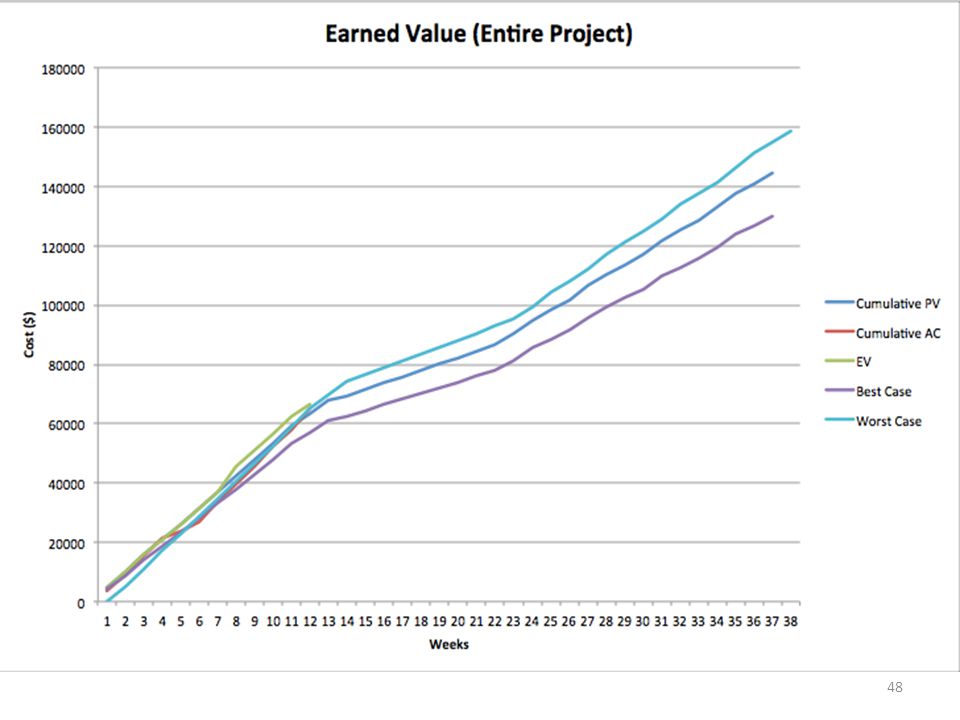
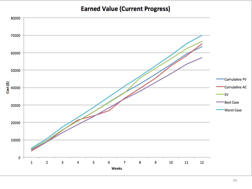
Project Timeline & Critical Path

47
Critical Tasks Foreseeable Risks Mitigation Routes 1.Define Requirements 2. Times for Production Stages 3. Times for FOD Inspection 4.Retrieve Costs of Different X-RAY System Alternatives 5. Establishing Distributions of discrete events 1a. Receiving definitive feedback from Lockheed Martin 1b. Verification of specific requirements from lack of quantitative data. 2a. Data not received from LMCO in sufficient time 3a. Data not received from LMCO in sufficient time 4. Failure to receive data from X-RAY vendors. 5a. Dependent upon receiving data in a timely fashion 1a: Define requirements based on the capabilities of the system with correlation to the goals and objectives of Lockheed Martin 1b. Use “dummy variables” in simulation and verify requirements based on output 2a. Ask for average times per stage from Lockheed Martin and apply a random number generator as a multiplier to obtain multiple data points 3a. Ask for average FOD inspection times per stages or position 3aa. Establish a percentage of time per shift spent searching and apply this to the simulation 4a. Estimate costs from available research 5a: Establishing “dummy variables” will enable our team to run multiple simulations, graph the output and establish these distributions 5aa. Obtaining these averages from Lockheed Martin and applying a random number generator as a multiplier will create multiple data points which can then be run through the simulation and graphed to find the various distributions.

51
Agenda Context Stakeholder Analysis & CONOPS
Approach & System Alternatives Methods & Models Project Management Future Steps

52
Plans for the near future
Results Modeling False Alarms Analysis of Results ROI Analysis Sensitivity Analysis Tying together GUI with Java code Conclusions and Recommendations

53
Questions?

54
Bibliography 1. American Science and Technology, “Z BACKSCATTER VAN,” AS&E, Massachusetts, USA, Tech. Report. ZBVDATA_080307, 2007. 2. American Science and Technology, “MOBILESEARCH HE,” AS&E, Massachusetts, USA, Tech. Report. MSHEDATA_012711, 2011. 3. American Science and Technology, “Omniview Gantry High-Performance Inspection System,” AS&E, Massachusetts, USA, Tech. Report. OVDATA_101711, 2011. 4. American Science and Technology, “Z PORTAL,” AS&E, Massachusetts, USA, Tech. Report. ZPORTALDATA_052510, 2010. 5. Batchel, B “Foreign Object Debris and Damage Prevention” [Online] Available: 6. Callerame, , "X-Ray Back scatter Imaging: Photography Through Barriers". Retrieved September, 2014 Available: 7.”CTOL SWBS Manufacturing Sequence Flow” [Online] Availablhttp://information2share.wordpress.com/2011/05/25/ctol-swbs-manufacturing-sequence-flow/ 8. Garber, M , Diagnostic imaging and differential diagnosis in 2 case reports , J Orthop Sports Phys Ther. , vol 35 , no , p.745 – 754 9. Gemini® 7555". Retrieved September , 2014 Available: 10. Fessle, C J, , "Physics of Projection Radiography ". RetrievedSeptember , 2014 Available: Radiography". RetrievedSeptember , 2014 Available: 11. FOREIGN OBJECT DAMAGE PREVENTION. [Online]. Available: 12. FOD PREVENTION GUIDELINE [Online]. Available: nafpiguideline.pdf

55
Bibliography Butler, Amy. "F-35 Deal Targets Unit Cost Below $100 Million." Aviation Week. N.p., n.d. Web. 10 Nov F35.com. N.p., n.d. Web. 11 Oct "BAE Systems completes 150th aircraft for F35 fighter programme". King, Samuel Jr. "First F-35 arrives at Eglin." U.S. Air Force, 15 July Retrieved: 20 July 2011. Pae, Peter. "Stealth fighters fly off the radar". Los Angeles Times, 23 April Retrieved 27 April 2008. "Iraq Accepts First Lockheed Martin F-16 Aircraft · Lockheed Martin". Retrieved 13 September 2014. Davies and Dildy 2007, p. 249 "McDonnell Douglas F-15 Streak Eagle fact sheet".National Museum of the United States Air Force. Retrieved 24 September 2010. "Analysis of the Fiscal Year 2012 Pentagon Spending Request." Cost of war, 15 February Retrieved: 31 August 2013.

56
Fighter Jet Slide References
Butler, Amy. "F-35 Deal Targets Unit Cost Below $100 Million." Aviation Week. N.p., n.d. Web. 10 Nov F35.com. N.p., n.d. Web. 11 Oct "BAE Systems completes 150th aircraft for F35 fighter programme". King, Samuel Jr. "First F-35 arrives at Eglin." U.S. Air Force, 15 July Retrieved: 20 July 2011. Pae, Peter. "Stealth fighters fly off the radar". Los Angeles Times, 23 April Retrieved 27 April 2008. "Iraq Accepts First Lockheed Martin F-16 Aircraft · Lockheed Martin". Retrieved 13 September 2014. Davies and Dildy 2007, p. 249 "McDonnell Douglas F-15 Streak Eagle fact sheet".National Museum of the United States Air Force. Retrieved 24 September 2010. "Analysis of the Fiscal Year 2012 Pentagon Spending Request." Cost of war, 15 February Retrieved: 31 August 2013.

57
BACK UPS

58
Inspection Probability Of Detection
Model

60
WBS 1.1

61
WBS 1.2

62
WBS 1.3

63
WBS 1.4

64
WBS 1.5

65
WBS 1.6

66
Differential Imaging Requirements
DIR # Requirement Definition DIR.1.O Supplier shall provide LM the capability to customize the Differential Imaging Software. DIR.2.0 A site license for all software required for LM to customize the system Differential Imaging Software shall be submitted for approval 6 months prior to installation on LM intranet assets. DIR.3.0 Installation on LM intranet assets will occur 90 days prior to installation. DIR.4.0 Two training courses to educate LM employees in the customization of the Differential Imaging Software. DIR.5.0 Each class shall be for 10 or less lM employees and conducted immediately after the training at the LM Fort Worth Facility. DIR.6.0 Differential Imaging software shall support the use of multiple algorithms to detect images

67
X-Ray Safety Requirements
XR.1.0 – System occupational exposure shall be in accordance with OSHA requirements. Supplier shall provide an X-Ray Exposure Protection Plan that addresses the following areas. XR The Plan shall be approved by LM 90 days prior to installation. Radiation Exposure Limits X-Ray Exams of Pregnant or Potentially Pregnant Women Personnel Monitoring Exposure Records Pregnant Authorized Users Posting Notices Inspections XR Radiation workers shall not receive a dose in 1 calendar quarter over the following limits: Deep Dose Equivalent millirem (mrem) Lens Dose Equivalent 3,750 mrem Shallow Dose Equivalent (skin) 12,500 mrem Shallow Dose Equivalent (extremities) 12,500 mrem Approach & System Alternatives
 Lens Dose Equivalent 3,750 mrem. Shallow Dose Equivalent (skin) 12,500 mrem. Shallow Dose Equivalent (extremities) 12,500 mrem. Approach & System Alternatives.")
Similar presentations


>")


