Download presentation
Presentation is loading. Please wait.

1
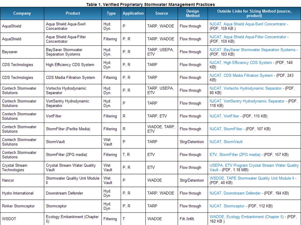
SMP Sizing in Redevelopment Projects Scenarios are countless Tools –Simple method –CN back calculation –Peak Discharge Rate Chapter 10 Criteria List of Verified Practices

3
Site Description Total area = 4 acres Disturbed are = 1 acre Impervious area =.6 acre Precipitation = 1” Storm Type 2 Justification Sizing and SMPs selection –4 scenarios Justification

4
Bethlehem, NY Site information –approximately 29.2% Imp –florist, green houses, parking, planting beds Proposed development –54% impervious –condominium complex, 9 buildings and 4 covered garages Constraints –relocating a sanitary sewer –maintaining setbacks Proposed practice –CDS units –Underground storage

6
Scenario 1 Reconstruction of existing impervious area not exceeding footprint. Selected Practice: Reduction of Impervious area by 25% Plan appropriately Document footprint reduction Ensure adequate infiltration Soil amendment Decompaction

8
Redevelopment Project with an Existing Detention Pond Keep the detention pond Address WQ treatment

10
WQv Calculation -1

11
WQv Calculation –2 100% Impervious Reduce upstream drainage and control an area that is all impervious. < <

12
WQv Calculation –3 Rv Constant

13
Scenario 2 Reconstruction of existing impervious area not exceeding footprint. Selected Practice: Infiltration Trench Calc. WQv x 25% Locate sub-catchment & diversion structure Check feasibility & limitations Document maintenance plan, etc.

14
Change of hydrology Change of design point focus on priority pollutant areas Rv no less than pre construction storage design Essential to define design point and subcatchments calc Wqv based on drainage area Rv. no less than preconstruction Earth google location of daycare center project soil type 40% A, 60% B imp. Reductions 5% change of hydrology number of existing dry wells 8 number of future dry-wells 5 Relocation of imp. Area relocation of dry detention pond open channel design for wqv Infiltration by soil testing/de-compaction/creating depression area

15
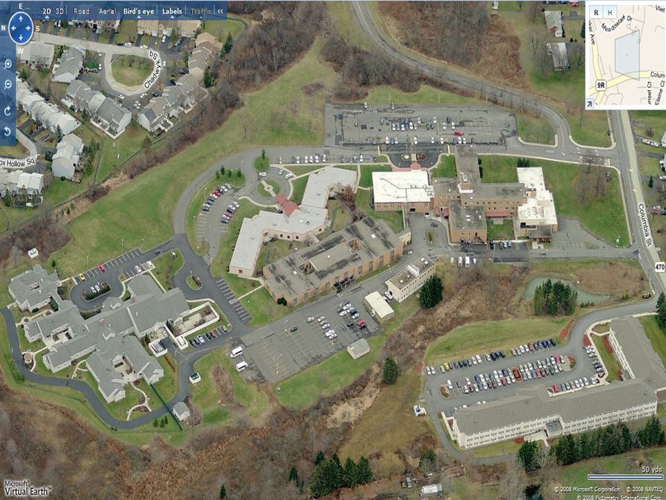
Site Description Eddy Greenhouses Nursing facility in Cohoes Area encompass 22 acres Northwestern portion of the property undeveloped (wetlands) Remainder is buildings and parking areas Existing impervious area 8.29 acres Proposed construction 16 Greenhouses –New construction 7.8 acres –Reconstruction 6.17 acres
 Remainder is buildings and parking areas Existing impervious area 8.29 acres Proposed construction 16 Greenhouses –New construction 7.8 acres –Reconstruction 6.17 acres")
17
Redevelopment Project with an Existing Detention Pond May modify the pond to meet pond design standards

18
Redevelopment Project with Increased Footprint

20
Proposed Plan Eddy Greenhouses Reduce impervious area by 25% Design a P-1 Pond Maintain existing water quantity controls in pond Provide treatment for all the new disturbance Provide treatment for a portion of the existing imperviousness Allow sheet flow for ½ of the site that did not have detention in existing condition Did not restore soil property Increase HSG for new pervious area

21
Scenario 3 Reconstruction of existing impervious area not exceeding footprint. Selected Practice: Hydrodynamic System Back calc. CN If only imp. Connected, CN = 98 Define flow rate Locate sub-catchment, flow splitter Look up the corresponding model from table 1 Check all the requirements for suitability of the practice, feasibility, limitations (head, soil, separation distance, etc.) Document calculation method, manufacturer’s recommendation, maintenance plan, etc.
 Document calculation method, manufacturer’s recommendation, maintenance plan, etc..")
22
Redevelopment Project with Increased Footprint

26
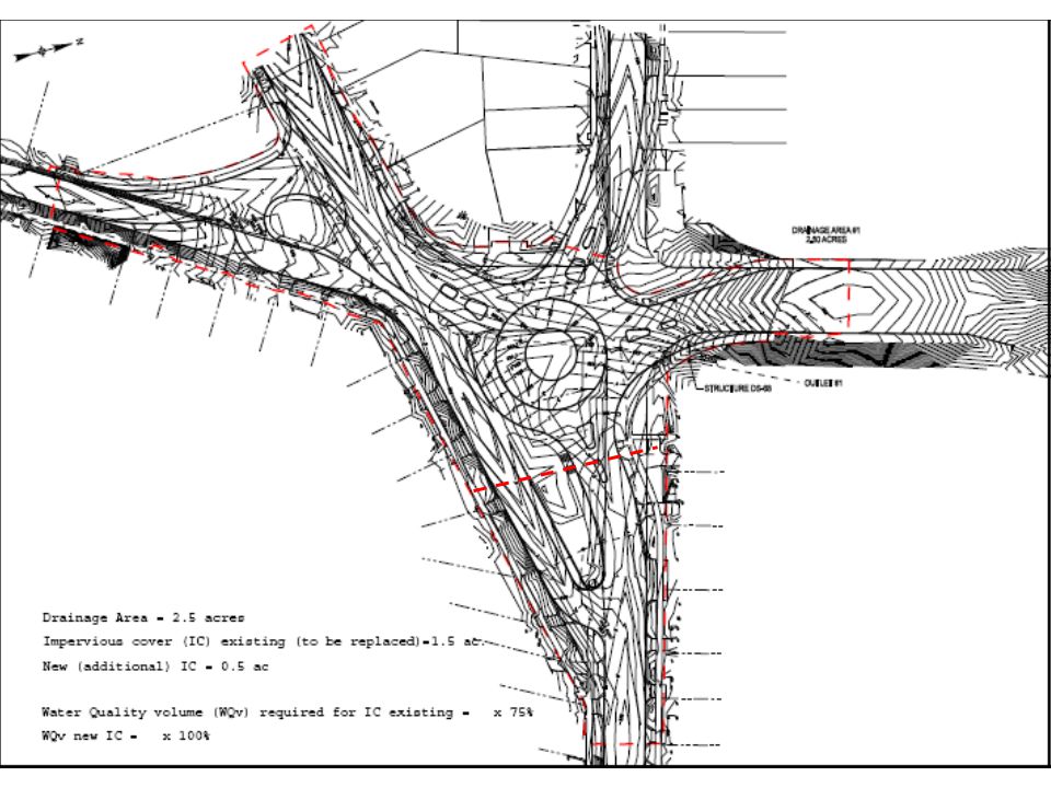
InputsParameterRedevelop.Units New Construction Site AcreageA2acres0.5 Impervious AreaIA1.5acres0.5 Impervious Cover%I75%100 Runoff CoefficientRv=.05+.009*I0.73constant0.95 Min. R v RvRv 0.2constant0.2 90% RainfallP1inches1 Water Quality VolumeWQ v = [PR v A]/120.1216667Acre-Feet0.0395833 5299.8 ft^3 1724.25 Alternative Practice, sized to 75% of WQv, define priority areas that generate a runoff volume equivalent to the target WQv. Rv constant. 0.753974.85 Total (ft^3) 5699.1
")
28
Equations WQv = [PRvA]/12 Rv=.05+.009*I I = imperviousness P= precipitation (inch) A= area
![Equations WQv = [PRvA]/12 Rv= *I I = imperviousness P= precipitation (inch) A= area](http://images.slideplayer.com/9/2532503/slides/slide_28.jpg "Equations WQv = [PRvA]/12 Rv= *I I = imperviousness P= precipitation (inch) A= area")
32
CN Back-Calculation Peak Discharge Rate

34
http://www.dec.ny.gov/chemical/29089.html

35
Hydrodynamic Systems Vortechs System http://www.dec.ny.gov/chemical/29089.html

37
Hydrodynamic Systems

38
WQv V SM + V DL + (D P x A RG ) V SM = A RG x D SM x n SM V DL (optional) = A RG x D DL x n DL where: V SM = volume of the soil media [cubic feet] V DL = volume of the drainage layer [cubic feet] A RG = rain garden surface area [square feet] D SM = depth of the soil media, typically 1.0 to 1.5 feet [feet] D DL = depth of the drainage layer, typically.05 to 1.0 feet [feet] D P = depth of ponding above surface, maximum 0.5 feet [feet] n SM = porosity of the soil media (≥20%) n DL = porosity of the drainage layer (≥40%) WQv= Water Quality Volume [cubic feet], as defined in Chapter 4 of the New York Stormwater Management Design Manual Alternative Practices Rain Garden
![WQv V SM + V DL + (D P x A RG ) V SM = A RG x D SM x n SM V DL (optional) = A RG x D DL x n DL where: V SM = volume of the soil media [cubic feet] V DL = volume of the drainage layer [cubic feet] A RG = rain garden surface area [square feet] D SM = depth of the soil media, typically 1.0 to 1.5 feet [feet] D DL = depth of the drainage layer, typically.05 to 1.0 feet [feet] D P = depth of ponding above surface, maximum 0.5 feet [feet] n SM = porosity of the soil media (≥20%) n DL = porosity of the drainage layer (≥40%) WQv= Water Quality Volume [cubic feet], as defined in Chapter 4 of the New York Stormwater Management Design Manual Alternative Practices Rain Garden](http://images.slideplayer.com/9/2532503/slides/slide_38.jpg "WQv V SM + V DL + (D P x A RG ) V SM = A RG x D SM x n SM V DL (optional) = A RG x D DL x n DL where: V SM = volume of the soil media [cubic feet] V DL = volume of the drainage layer [cubic feet] A RG = rain garden surface area [square feet] D SM = depth of the soil media, typically 1.0 to 1.5 feet [feet] D DL = depth of the drainage layer, typically.05 to 1.0 feet [feet] D P = depth of ponding above surface, maximum 0.5 feet [feet] n SM = porosity of the soil media (≥20%) n DL = porosity of the drainage layer (≥40%) WQv= Water Quality Volume [cubic feet], as defined in Chapter 4 of the New York Stormwater Management Design Manual Alternative Practices Rain Garden")
40
Redevelopment Project with Increased Footprint

42
Green Roof Design Total WQv Treatment by Porous Pavement and Green Roof

Similar presentations


 Center for Watershed Protection Dave Briglio, P.E. MACTEC.>")


 SEMINAR INLAND EMPIRE ASCE & APWA LOW IMPACT DEVELOPMENT (LID) SEMINAR LID FACILITY DESIGN Prepared.>")
 330-725-5829 (fax) Local leadership for soil and.>")