Download presentation
Presentation is loading. Please wait.

1
Dye sensitized photo electrochemical solar cells
In the name of God Dye sensitized photo electrochemical solar cells Represented by : maziar marandi PhD student in physics address : Project of nanotechnology course Department of physics – sharif university of technology Date : 1382 / 10 / 13

2
Subjects that we are going to say :
What,s a solar cell nanoporous and mesoporous materials What are the dye sensitized solar cells Dye sensitized photo electrochemical solar cells manufactured by nano & mesoporous materials

3
What,s a solar cell ? Solar cell is a device that convet the energy of sun to electricity .

4
The basic steps of photovoltaic energy conversion :
light absorption Charge separation Charge collection

5
A high efficiency version of Si sollar cells

6
Porous material : Nano porous (with sizes less than 2 nm)
Mesoporous (with sizes between 2-50 nm) Microporous ( with sizes larger than 100nm) Porous titania Why are the nanoporous materials so important ?
 Microporous ( with sizes larger than 100nm) Porous titania. Why are the nanoporous materials so important")
7
1 gram Spans Three Tennis Courts!
TEM of Titania or TiO2 1 gram Spans Three Tennis Courts!

8
Dye sensitized electrochemical nano & mesoporous solar cells
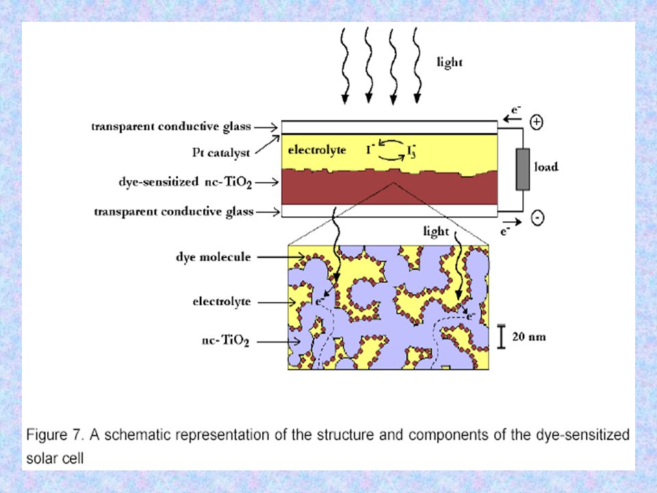
In contrast to the all-solid conventional semiconductor solar cells, the dye-sensitized solar cell is a photoelectrochemical solar cell

9
2. dye molecules attached to the surface of the nc-TiO2
Historical discussion (1873 – 1990) a dye sensitized solar cells are comprised from: 1. transparent conducting glass electrode coated with porous nanocrystalline TiO2 (nc-TiO2) 2. dye molecules attached to the surface of the nc-TiO2 3. an electrolyte containing a reduction-oxidation couple such as I-/I3 4. a catalyst coated counter-electrode
 a dye sensitized solar cells are comprised from: 1. transparent conducting glass electrode coated with porous nanocrystalline TiO2 (nc-TiO2) 2. dye molecules attached to the surface of the nc-TiO2. 3. an electrolyte containing a reduction-oxidation couple such as I-/I3. 4. a catalyst coated counter-electrode.")
11
{ 1. s + hƲ → s* absorption (anode)
operating cycle can be summarized in chemical reaction terminology as (Matthews et al. 1996): { 1. s + hƲ → s* absorption (anode) s* → s + e- (TiO2) electron injection 2s+ + 3I - → 2s + I regeneration I e - (Pt) → 3I cathode e - + hƲ → e - (TiO2) cell
: { 1. s + hƲ → s* absorption (anode) s* → s + e- (TiO2) electron injection. 2s+ + 3I - → 2s + I3 - regeneration. I e - (Pt) → 3I - cathode. e - + hƲ → e - (TiO2) cell.")
12
Due to the energy level positioning in the system,
The cell is capable of producing voltage between its electrodes and across the external load.

13
Theoretical issues of the dye cell operation
The need for unique theoretical considerations of the photovoltaic effect in the DSSCs arises from the fundamental differences in the operation between the DSSCs and the traditional semiconductor pn-junction solar cells: The light absorption and charge transport occurs in different materials The charge separation is not induced by long-range electric field . It,s because of other kinds of kinetic and energetic reasons at the dye covered semiconductor-electrolyte interface Generated opposite charges travel in different materials (therefore we don’t need to very pure material

14
Light absorption : In DSSCs the key point is dye sensitization of large band gap semiconductor electrode with special dyes tuned to absorb the incoming photons

15
Adsorption of the dye molecule :
Adsorption of dye molecule to semiconductor surface ussually takes place via special anchoring groups attached to dye molecule (carboxylic groups in N3 dye) Charge absorption via MLCT excitation : The absorption of a photon by the dye molecule happens via an excitation between the electronic states of the molecule. For example the N3 dye has two absorption maxima in the visible region at 518 nm and at 380 nm (Hagfeldt & Grätzel 2000).
 Charge absorption via MLCT excitation : The absorption of a photon by the dye molecule happens via an excitation between. the electronic states of the molecule. For example the N3 dye has two absorption. maxima in the visible region at 518 nm and at 380 nm (Hagfeldt & Grätzel 2000).")
16
The effect of spectral sensitization is made evident in this figure :

17
Chrge transport : electron transport (in semiconductor ) Ion transport (in the redox electrolyte) Is the electron transport derived by build-in electric field or by diffusion ? The electrolyte in the DSSCs is usually an organic solvent containing the redox pair I-/I3-, which in this case works as a hole-conducting medium. Ion transport : 2s+ + 3I - → 2s + I regeneration I e - (Pt) → 3I chatode - reduction
 → 3I - chatode - reduction.")
18
Recombination: Recombination of the generated electrons with holes in the dye-sensitized nanostructured TiO2 electrode can in principle occur both after the electron injection or during its migration in the TiO2 electrode on its way to the electrical back contact. the dye solar cell does not seem to suffer from the recombination losses at the grain boundaries at all. The reason for this is that only electrons are transported through the semiconductor particles, while holes (oxidized ions) are carried by the electrolyte. the dye cell works as a majority carrier device, similar to a metal-semiconductor junction or a Schottky diode (Green1982, p. 175). According to Huang et al. (1997) the net recombination reaction at the TiO2 - electrolyte interface is a two electron reaction I e - (Pt) → 3I -
 are carried by the electrolyte. the dye cell works as a majority carrier device, similar to a metal-semiconductor junction or a Schottky diode (Green1982, p. 175). According to Huang et al. (1997) the net recombination reaction at the TiO2 - electrolyte interface is a two electron reaction. I e - (Pt) → 3I -")
19
Interfacial kinetics:
The electron percolation through the nanostructured TiO2 has been estimated to occur in the millisecond to second range (Hagfeldt & Grätzel 1995).
.")
20
Materials of the dye sensitized solar cells :
Substrates: fluorine-doped tin oxide (SnO2 : F) Indium tin oxide (In2O3 : Sn or ITO) 8-15 Ώ/sq Nanoparticle electrodes: Oxide semiconductors are preferential in photoelectrochemistry because of their exceptional stability against photo-corrosion on optical excitation in the band gap (Kalyanasundaram & Grätzel 1998). Furthermore, the large band gap (>3 eV) of the oxide semiconductors is needed in DSSCs for the transparency of the semiconductor electrode for the large part of the solar spectrum. TiO2 , ZnO, CdSe , CdS, WO3 , Fe2O3, SnO2, Nb2O5 ,Ta2O5 (references in Hagfeldt & Grätzel 1995).
 Indium tin oxide (In2O3 : Sn or ITO) 8-15 Ώ/sq. Nanoparticle electrodes: Oxide semiconductors are preferential in photoelectrochemistry because of their exceptional stability against photo-corrosion on optical excitation in the band gap (Kalyanasundaram & Grätzel 1998). Furthermore, the large band gap (>3 eV) of the oxide semiconductors is needed in DSSCs for the transparency of the semiconductor electrode for the large part of the solar spectrum. TiO2 , ZnO, CdSe , CdS, WO3 , Fe2O3, SnO2, Nb2O5 ,Ta2O5 (references in Hagfeldt & Grätzel 1995).")
21
Sensitizer dyes: 1. Absorption: The dye should absorb light at wavelenghts up to about 920nanometers, i.e. the energy of the exited state of the molecule should be about 1.35 eV above the electronic ground state corresponding to the ideal band gap of a single band gap solar cell (Green 1982 p. 89). 2. Energetics: To minimize energy losses and to maximize the photovoltage, the exited state of the adsorbed dye molecule should be only slightly above the conduction band edge of the TiO2, but yet above enough to present an energetic driving force for the electron injection process. For the same reason, the ground state of the molecule should be only slightly below the redox potential of the electrolyte 3. Kinetics: The process of electron injection from the exited state to the conduction band of the semiconductor should be fast enough to outrun competing unwanted relaxation and reaction pathways. The excitation of the molecule should be preferentially of the MLCT-type. 4. Stability: The adsorbed dye molecule should be stable enough in the working environment (at the semiconductor-electrolyte interface) to sustain about 20 years of operation at exposure to natural daylight, i.e. at least 108 redox turnovers (Hagfeldt & Grätzel 2000). 5. Interfacial properties: good adsorption to the semiconductor surface 6. Practical properties: e.g. high solubility to the solvent used in the dye impregnation.
. 2. Energetics: To minimize energy losses and to maximize the photovoltage, the. exited state of the adsorbed dye molecule should be only slightly above the. conduction band edge of the TiO2, but yet above enough to present an energetic. driving force for the electron injection process. For the same reason, the ground. state of the molecule should be only slightly below the redox potential of the. electrolyte. 3. Kinetics: The process of electron injection from the exited state to the conduction band of the semiconductor should be fast enough to outrun competing unwanted relaxation and reaction pathways. The excitation of the molecule should be preferentially of the MLCT-type. 4. Stability: The adsorbed dye molecule should be stable enough in the working environment (at the semiconductor-electrolyte interface) to sustain about 20 years of operation at exposure to natural daylight, i.e. at least 108 redox turnovers (Hagfeldt & Grätzel 2000). 5. Interfacial properties: good adsorption to the semiconductor surface. 6. Practical properties: e.g. high solubility to the solvent used in the dye. impregnation.")
22
Dyes : Dyes having the general structure ML2(X)2, where L stands for 2,2´-bipyridyl-4,4´-dicarboxylic acid, M for ruthenium or osmium and X for halide, cyanide, thiocyanate, or water have been found promising (Hagfeldt & Grätzel 2000( Among these the cis-RuL2(NCS)2, also called the N3 dye has shown superior performance and has been the top choice for dye-sensitized solar cells for long.
2, where L stands for 2,2´-bipyridyl-4,4´-dicarboxylic acid, M for ruthenium or osmium and X for halide, cyanide, thiocyanate, or water have been found promising (Hagfeldt & Grätzel 2000( Among these the cis-RuL2(NCS)2, also called the N3 dye has shown superior performance and has been the top choice for dye-sensitized solar cells for long.")
23
Electrolytes: The electrolyte used in the DSSCs consists of iodine (I-) and triiodide (I3-) as a redox couple in a solvent with possibly other substances added to improve the properties of the electrolyte and the performance of the operating DSSC. Ideal characteristics of the redox couple for the DSSC electrolyte 1. Redox potential thermodynamically (energetically) favorable with respect to the redox potential of the dye to maximize cell voltage 2. High solubility to the solvent to ensure high concentration of charge carriers inthe electrolyte 3. High diffusion coefficients in the used solvent to enable efficient mass transport 4. Absence of significant spectral characteristics in the visible region to prevent absorption of incident light in the electrolyte 5. High stability of both the reduced and oxidized forms of the couple to enable long operating life 6. Highly reversible couple to facilitate fast electron transfer kinetics 7. Chemically inert toward all other components in the DSSC
 and triiodide (I3-) as a redox couple in a solvent with possibly other substances added to improve the properties of the electrolyte and the performance of the operating DSSC. Ideal characteristics of the redox couple for the DSSC electrolyte. 1. Redox potential thermodynamically (energetically) favorable with respect to the redox potential of the dye to maximize cell voltage. 2. High solubility to the solvent to ensure high concentration of charge carriers inthe electrolyte. 3. High diffusion coefficients in the used solvent to enable efficient mass transport. 4. Absence of significant spectral characteristics in the visible region to prevent absorption of incident light in the electrolyte. 5. High stability of both the reduced and oxidized forms of the couple to enable long operating life. 6. Highly reversible couple to facilitate fast electron transfer kinetics. 7. Chemically inert toward all other components in the DSSC.")
24
solvent : 1. The solvent must be liquid with low volatility at the operating temperatures (-40°C - 80°C) to avoid freezing or expansion of the electrolyte, which would damage the cells 2. It should have low viscosity to permit the rapid diffusion of charge carriers 3. The intended redox couple should be soluble in the solvent 4. It should have a high dielectric constant to facilitate dissolution of the redox couple 5. The sensitizing dye should not desorb into the solvent 6. It must be resistant to decomposition over long periods of time 7. And finally from the point of view of commercial production, the solvent should be of low cost and low toxicity Examples of the solvents used in the electrolytes in DSSCs are: acetonitrile (O'Regan & Grätzel 1991), methoxyacetonitrile (Ferber et al. 2000), methoxypropionitrile (Rijnberg et al. 1998), glutaronitrile (Kohle et al. 1997), butyronitrile (Kay & Grätzel 1996), ethylene carbonate (O'Regan & Grätzel 1991) and propylene carbonate (Smestad et al. 1994).
 to avoid freezing or expansion of the electrolyte, which would damage the cells. 2. It should have low viscosity to permit the rapid diffusion of charge carriers. 3. The intended redox couple should be soluble in the solvent. 4. It should have a high dielectric constant to facilitate dissolution of the redox couple. 5. The sensitizing dye should not desorb into the solvent. 6. It must be resistant to decomposition over long periods of time. 7. And finally from the point of view of commercial production, the solvent should be of low cost and low toxicity. Examples of the solvents used in the electrolytes in DSSCs are: acetonitrile (O Regan & Grätzel 1991), methoxyacetonitrile (Ferber et al. 2000), methoxypropionitrile (Rijnberg et al. 1998), glutaronitrile (Kohle et al. 1997), butyronitrile (Kay & Grätzel 1996), ethylene carbonate (O Regan & Grätzel 1991) and propylene carbonate (Smestad et al. 1994).")
25
Counter electrode catalysts
Platinum Carbon Electrical contacts: silver paint and adhesive copper tape A iodine based electrolyte is highly corrosive attacking most metals, such as silver, aluminum, copper, nickel and even gold

26
Thank you

Similar presentations


>")


