Download presentation
Presentation is loading. Please wait.

1
Past, present and future of Gravitational Wave detection Science J. Alberto Lobo, Bellaterra, 13-October-2004

2
Presentation summary 1.Current GW detection research status: Acoustic detectors Interferometers LISA 2.LPF and the LTP 3.The Diagnostics and DMU subsystems 4.Future prospects

3
Earth based GW detectors There are two detection concepts at present Acoustic detection: Interferometric detection: Based on resonant amplification of GW induced tidal effects. Based on GW induced phase shifts on e.m. waves. VIRGO, LIGO, GEO-600, TAMA EXPLORER, NAUTILUS, AURIGA, ALLEGRO, NIOBE

4
Bar concept Idea of an acoustic detector (bar) is to link masses with a spring: so that and GW signal gets selectively amplified around frequency . Strong directionality

5
Real bar detectors J. Weber Two well separated aluminum bars (~1000 km) Resonance at ~1 kHz Piezoelectric non-resonant transducers Impulse sensitivity: h~10 -16 Coincidence analysis Tens of sightings claimed in one year Claims questioned and eventually disproved Hawking and Gibbons: energy innovation theory Giffard: bar quantum limit New generation cryogenic and ultra-cryogenic bars
 Resonance at ~1 kHz Piezoelectric non-resonant transducers Impulse sensitivity: h~ Coincidence analysis Tens of sightings claimed in one year Claims questioned and eventually disproved Hawking and Gibbons: energy innovation theory Giffard: bar quantum limit New generation cryogenic and ultra-cryogenic bars.")
6
EXPLORER detector at CERN (ROG)
")
7
NAUTILUS, Frascati Dilution refrigerator: 50 mK Resonant transducer h ~ 5x10 -19

8
Resonant motion sensor Principle: Resonant energy transfer to & fro Mecahnical amplification Beat spectrum:

9
Bar detector sensitivity Maximum bandwidth: NAUTILUS, 1999

10
IGEC IGEC (International Gravitational Event Collaboration) Essential resultsEssential results: No impulse signals above 4x10 -18 Negligible false alarm when n>3 (<1/10 4 years) Various controversial, single detector claims available… Remarkable… but insufficient
 Essential resultsEssential results: No impulse signals above 4x Negligible false alarm when n>3 (<1/10 4 years) Various controversial, single detector claims available… Remarkable… but insufficient")
11
MiniGrail, Leiden

12
Interferometric detector working principle Resonance condition :

13
Interferometric detector design Fabry-Pérot arms: Photodiode: dark fringe: Photon flux waste Shot noise important Light recycling technique: Power recycling Signal recycling Delay lines

14
Details of VIRGO Cascina site, near Pisa

15
Details of VIRGO Vacuum pipe Highly reflecting mirror

16
Summary status of LIGO Nov. 1999: Official inauguration Feb. 2002: Engineering run E7, 6 months Sep. 2002: Science run S1, 17 days, + TAMA + GEO-600 Feb. 2003: Science run S2, 59 days, Nov. 2003: Science run S3, 70 days, + TAMA + GEO-600 End of 2004: Science run S4: ~4 weeks Spring 2005: Commissioning, ~6 months Autumn 2005: Science run S5, ~6 months After: Full observatory operation

17
LIGO Science run S3, and GEO-600

19
there are many GW sources at low frequencies Earth-based detectors are seismic noise limited If… but… then… the solution is to go out to space

20
LISA

21
Brief chronology: 1993.Europe/US team submits LISA proposal as M3 project of ESA’s Horizon-2000 Science Programme. 1994. LISA is changed to cornerstone mission in ESA’s Horizon-2000 Plus, and approved as ESA alone. 1997. New studies to reduce cost: LISA is redefined as a three S/C Constellation, 1.4 ton payload. NASA joins in (50% + 50%), launch advanced to ~2010. 1998. ESA’s FPAG recommends industrial study phase. 1999. System & Technology Study begins. Prime is Dornier Satellitensysteme, LIST strongly involved. 2000. Final Report delivered to ESA. 2003. TRIP Review panel considers LISA medium risk. 2003. ESA’s 4 th Nov SPC approves LISA, and LPF. 2004. NASA’s new exploration programme defers LISA to 2013.
, launch advanced to ~ ESA’s FPAG recommends industrial study phase System & Technology Study begins. Prime is Dornier Satellitensysteme, LIST strongly involved Final Report delivered to ESA TRIP Review panel considers LISA medium risk ESA’s 4 th Nov SPC approves LISA, and LPF NASA’s new exploration programme defers LISA to")
22
LISA concept Test masses 5 million km, 30 mHz Transponder scheme

23
LISA sensitivity

24
Comparison with Earth detectors

25
LISA’s assured sources

26
Cumulative Weekly S/N Ratios during Last Year Before MBH-MBH Coalescence

28
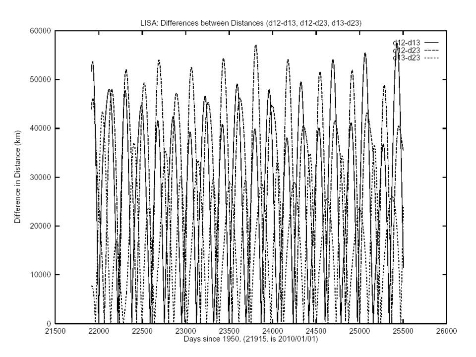
LISA orbit

29
Orbit dynamics 1 o inclination 0.01 eccentricity

32
The three spacecraft Thermal shield Downlink antennas FEEP Baffle Solar panels Support structures Science module Star tracker

33
The science module

34
LISA mission summary Detection of GWs, sensitivity: 4x10 -21 at 1 mHz Payload: Objective: Six capacitive inertial sensors Six set of four FEEP per S/C Two lasers per S/C: ND-YAG, 1064 nm, 1 W Six test masses of Au-Pt alloy, 40 mm a side, in three S/C Fabry-Perot cavities, stability 30 Hz/sqrt(Hz), transponders Quadrant photodiode detectors, fringe resol: 30 cm Cassegrain telescopes Orbit:1 AU, 0.01 ecc, 1 deg ecliptic inclin, 20 deg behind Earth Launcher:NASA’s Delta, launch date: 2013 Spacecraft:Total mass: 1380 kg Total power: 940 W/composite Pointing performance: few n-rad/sqrt(Hz) in band Science data rate: 672 bps each S/C Telemetry:7 kps, 9 hour/2 days; Deep Space Network
, transponders Quadrant photodiode detectors, fringe resol: 30 cm Cassegrain telescopes Orbit:1 AU, 0.01 ecc, 1 deg ecliptic inclin, 20 deg behind Earth Launcher:NASA’s Delta, launch date: 2013 Spacecraft:Total mass: 1380 kg Total power: 940 W/composite Pointing performance: few n-rad/sqrt(Hz) in band Science data rate: 672 bps each S/C Telemetry:7 kps, 9 hour/2 days; Deep Space Network")
35
LISA PathFinder (formerly SMART-2) LISA’s requirements are extremely demanding. Drag free subsystem can not be fully tested on Earth. A previous, smaller technology mission, will assess feasibility: LPF It will carry on board the LTP. However it will be in a smaller scale, both in size and sensitivity. Essentially, LTP will check: drag free technology picometre interferometry other important subsystems and software

36
LPF

37
LPF Funding Agencies and countries Mission: DLR SSO Payload: Prime contractor: – Platform: Astrium UK – Payload: Astrium Friedrichshafen

38
LTP concept 1. One LISA arm is squeezed to 30 centimetres: 2. Relax sensitivity by one order of magnitude, also in band: 30 cm LTP Objectives : Drag-free Interferometry Other…

39
LTP functional architecture Ground Support Equipment (GSE) LTP flight dynamics simulator Integration GSE IS GSE Optical metrology GSE
 LTP flight dynamics simulator Integration GSE IS GSE Optical metrology GSE")
40
LPF orbit Lagrange L1 Launch: Sep-2008 Travel time: Mission lifetime: Launch vehicle: Rockot from Plesetsk

41
LTP functional architecture Inertial sensors (IS) Charge management system IS core Caging Mechanism IS Front End Electronics
 Charge management system IS core Caging Mechanism IS Front End Electronics")
42
Drag-free subsystem For LISA to work test masses must be (nominally) in free fall. But there are perturbations which tend to spoil this: External agents, e.g., solar pressure, magnetic fields… Internal disturbances, caused by instrumentation itself To compensate for these, a drag-free system is implemented. It has two fundamental components: A position sensor An actuation system

43
Drag-free working concept Courtesy of S. Vitale

44
Drag-free working concept Courtesy of S. Vitale

45
Drag-free working concept Courtesy of S. Vitale

46
Drag-free working concept Courtesy of S. Vitale

47
Drag-free working concept Courtesy of S. Vitale

48
Drag-free working concept Courtesy of S. Vitale

49
Drag-free working concept Courtesy of S. Vitale

50
Drag-free working concept Courtesy of S. Vitale

51
Drag-free working concept Courtesy of S. Vitale

52
Capacitive position sensing principle Bias: few volts at 100 kHz Nanometre precision comfortably attained

53
Rotational and translational control example

54
Inertial sensor structure

55
LTP functional architecture Optical Metrology Unit (OMU) Optical Metrology Front End Electronics Laser Unit Optical Bench Acousto-optic modulator Laser
 Optical Metrology Front End Electronics Laser Unit Optical Bench Acousto-optic modulator Laser")
56
LTP optical metrology To interferometer: Mach-Zender heterodyne Power = 1 mW = 1.064 m Signal:

57
LTP interferometer Reference x1-x2x1 Frequency Readout: quadrant InGaAs photodiodes A CD B

58
The LTP EM optical bench

59
The LTP EM OB: after-shake tests: phase

60
LTP functional architecture LTP structure (LTPS) Structure Gravitational balance system Thermal Shield
 Structure Gravitational balance system Thermal Shield")
61
The LTP structure ASD, courtesy of S. Vitale

62
The LTP structure ASD, courtesy of S. Vitale

63
The LTP structure ASD, courtesy of S. Vitale

64
The LTP structure ASD, courtesy of S. Vitale

65
The LTP structure ASD, courtesy of S. Vitale

66
The LTP structure ASD, courtesy of S. Vitale

67
The science spacecraft The science spacecraft carries the the LTP and DRS, the micro-propulsion systems and the drag free control system. Total mass about 470kg Inertial sensor core assemblies mounted in a dedicated compartment within the central cylinder. DRS Colloid thrusters mounted on opposing outer panels. Payload electronics and spacecraft units accommodated as far away as possible from the sensors to minimise gravitational, thermal and magnetic disturbances. FEEP and cold-gas micro-propulsion assemblies arranged to provide full control in all axes. Courtesy of G. Racca

68
LTP functional architecture Diagnostics and Data Management Unit (DMU) Diagnostics end items DMU and diagnostics box
 Diagnostics end items DMU and diagnostics box")
69
DDS: Data Management & Diagnostics Subsystem Diagnostics items: Purpose: – Noise split up Sensors for: – Temperature – Magnetic fields – Charged particles Calibration: – Heaters – Induction coils DMU: Purpose: – LTP computer Hardware: – Data Processing Unit (DPU) – Power Distribution Unit (PDU) – Data Acquisition Unit (DAU) Software: – Process phase-meter readout – Charge management control – UV light control – Caging mechanism drive (TBC) – DFACS split (?)
 – Power Distribution Unit (PDU) – Data Acquisition Unit (DAU) Software: – Process phase-meter readout – Charge management control – UV light control – Caging mechanism drive (TBC) – DFACS split ( )")
70
Noise analysis concept Test mass equation of motion (1 dimension): In frequency domain: Thus spurious forces fake GW signals, with spectral density: LTP top level science requirement rephrased:
: In frequency domain: Thus spurious forces fake GW signals, with spectral density: LTP top level science requirement rephrased:")
71
Noise apportioning Direct forces on test mass: Thermal gradients Magnetic forces Fake interferometer noise Coupling to S/C: Test mass position fluctuations Drag free response delay Charged particle showers Diagnostics items

72
Noise reduction philosophy Problem: to assess the contribution of a given perturbation to the noise force f int. Approach: 1) Apply controlled perturbation to the system 2) Measure “feed-through” coefficient between force and perturbation: 3) Measure actual with suitable sensors 4) Estimate contribution of by linear interpolation: 5) Substract out from total detected noise: 6) Iterate process for all identified perturbations
 Apply controlled perturbation to the system 2) Measure feed-through coefficient between force and perturbation: 3) Measure actual with suitable sensors 4) Estimate contribution of by linear interpolation: 5) Substract out from total detected noise: 6) Iterate process for all identified perturbations.")
73
Example Courtesy of S. Vitale

74
Various diagnostics items Temperature and temperature gradients: – Sensors: thermometers at suitable locations – Control: heaters at suitable locations Magnetic fields and magnetic field gradients: – Sensors: magnetometers at suitable locations – Control: induction coils at suitable locations Charged particle showers (protons): – Sensors: radiation monitor (Mona Lisa) – Control: non-existent Direct forces Coupled to S/C Specifications follow from mission top level requirements
: – Sensors: radiation monitor (Mona Lisa) – Control: non-existent Direct forces Coupled to S/C Specifications follow from mission top level requirements")
75
Diagnostics science requirements Ref. num LISALTP Req. 107Temperature PSD (optical bench) 10 -4 K/ Hz Req. 108Temperature difference PSD (IS) 10 -5 K/ Hz10 -4 K/ Hz Value Magnetic Field T T/m Magnetic Field Fluctuation PSD 650 nT/ Hz 25 (nT/m)/ Hz Magnetic Field Gradient PSD Magnetic Field Gradient Magnitude Overflow for 10 8 p/cm 2 Solar Energetic Proton (SEP, >100 MeV) at peak flux B RM
 K/ Hz Req. 108Temperature difference PSD (IS) K/ Hz10 -4 K/ Hz Value Magnetic Field T T/m Magnetic Field Fluctuation PSD 650 nT/ Hz 25 (nT/m)/ Hz Magnetic Field Gradient PSD Magnetic Field Gradient Magnitude Overflow for 10 8 p/cm 2 Solar Energetic Proton (SEP, >100 MeV) at peak flux B RM.")
76
DDS current development status Thermal: NTC and RTD devices identified and procured (EM) FEE designed and built (EM) First round of tests and data analysis complete New tests underway Magnetic: Some preliminary studies and surveys New team has recently assumed responsibility Radiation monitor: Full conceptual design ready Front-end Electronics Designed Rest of components selected from ESA/NASA qualified parts Some other parts to be defined DMU: In situ design and manufacture (price) Advanced state of development, redundancy requested Software writing in progress
 FEE designed and built (EM) First round of tests and data analysis complete New tests underway Magnetic: Some preliminary studies and surveys New team has recently assumed responsibility Radiation monitor: Full conceptual design ready Front-end Electronics Designed Rest of components selected from ESA/NASA qualified parts Some other parts to be defined DMU: In situ design and manufacture (price) Advanced state of development, redundancy requested Software writing in progress")
77
Long term: – LISA is fully endorsed by FPAG and SSAC – Full, first class participation in LISA: Technology developments Science yield – LISA PathFinder: Fulfill accepted LTP/DDS commitments MEC funds until 2007, 3.9 MEU New projects needed until LPF launch in 2008 Create qualified Science and Technology teams Can Science already be done with LPF? Short-medium term: Conclusion and future prospects

79
End of presentation

80
IGEC

82
Garching delay line prototype

83
Delta launcher

84
LPF operation orbit and injection

86
FEEP (Field Emission Electric Propulsion) Cs or In ions Range: 0.1 N < F < 100 N Resolution: 0.1 N Power: 50 mW/ N Negligible sloshing Long life: 9 gr/thruster.2 yr Low noise, no mechanical parts LISA needs six sets of four thrusters per S/C for full drag free control
 Cs or In ions Range: 0.1 N < F < 100 N Resolution: 0.1 N Power: 50 mW/ N Negligible sloshing Long life: 9 gr/thruster.2 yr Low noise, no mechanical parts LISA needs six sets of four thrusters per S/C for full drag free control")
87
The entire payload

88
Various launcher alternatives RockotDneprAriane 5

89
The LTP optical bench

90
Thermal diagnostics: current status Sensor choice: NTC & RTD to be tested

91
PIC C HP 3440 2A IEEE-488 USB RS232 USB FEE Al block FOAM CH0 CH1 CH2 CH3 CH4 CH5 CH6 CH7 MUX, GAIN control 16 bit data NTC type sensor RTD type sensor Reference resistor. Vishay S102J 10k Test setup only. Not part of DMU-LTP LabVIEW NTC2 NTC1 NTC2 NTC3 NTC2 RTD1 RTD2 NTC3 NTC2 RTD2 Test Philosophy Thermal diagnostics: current status

92
Thermal diagnostics: clean room at NTE

93
Thermal diagnostics: foaming process

94
Thermal diagnostics: sensor inserts

95
Thermal diagnostics: first NTC results

96
Magnetometer top level requirements from LTP magnetic requirements (TBC). Magnetic Field10 μT Magnetic Field Gradient 5 μT Magnetic Field PSD650 nT Magnetic Field Gradient PSD 25 nT Sample rate: 0.33 sample/second (x 3 components) Bits/sample: 16 Range: variable (± 10 μT, ± 30 μT ± 100 μT) Resolution (FS/2 16 ) variable (0.305 nT, 0.91 nT, 3.05 nT) Noise (for SNR=10 dB in ± 10 μT range) 40 pt / sqrt Hz @ 0.15Hz Mass, power, drift. Survey of suitable magnetometer technologies. Candidate: Fluxgate Magnetometer. TechnologyFGMAMRMGMRMHEM MeasurementVectorial Range1 pT – 1 T100 pT- 1 T 1uT- 100 T Precision(noise)5-10 pT/√Hz @ 1 Hz3-10 nT/√Hz @ 1 Hz20 pT/√Hz @ 100 Hz10 nT/√Hz @ 1Hz Drift 0.2 nT/yr 30-50 ppm/ºC (temp) 600 ppm/ºC (temp) 600 ppm/ºC (temp) 600 ppm/ºC Power Consumption<0.5W Magnetic diagnostics
 Bits/sample: 16 Range: variable (± 10 μT, ± 30 μT ± 100 μT) Resolution (FS/2 16 ) variable (0.305 nT, 0.91 nT, 3.05 nT) Noise (for SNR=10 dB in ± 10 μT range) 40 pt / sqrt 0.15Hz Mass, power, drift. Survey of suitable magnetometer technologies. Candidate: Fluxgate Magnetometer. TechnologyFGMAMRMGMRMHEM MeasurementVectorial Range1 pT – 1 T100 pT- 1 T 1uT- 100 T Precision(noise) Hz Hz Hz10 1Hz Drift 0.2 nT/yr ppm/ºC (temp) 600 ppm/ºC (temp) 600 ppm/ºC (temp) 600 ppm/ºC Power Consumption<0.5W Magnetic diagnostics.")
97
Helmholtz coil configurations analysed: Preliminary magnetometer survey: flux-gate, Hall effect,…

98
Radiation monitor 18 x 18 mm 2 10 x 10 mm 2 10 mm Telescopic Configuration reduces the Angular acceptance on particles and gives a better spectral resolution.

99
Radiation Monitor Data Control & Analysis

100
DMU Block Diagram

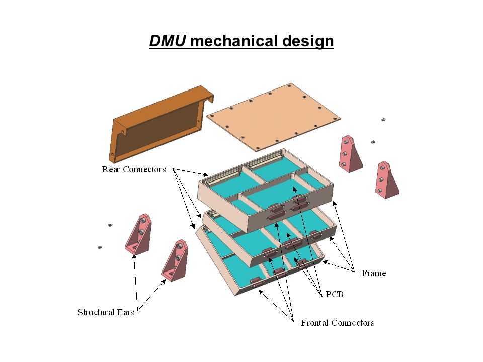
102
DMU mechanical design

Similar presentations


 January 2008 GEO simulation meeting Attempts to measure the Optical Spring in GEO600.>")


 (F.Ricci-G.Frossati) Objectives: -Design new suspension elements for the last stage.>")


 part II: the Vibration.>")

