Download presentation
Presentation is loading. Please wait.

1
A PRESENTATION ON STUDENTS’ WORK EXPERIENCE SCHEME (SIWES) BY AKINYOMI OLUWAFEMI JOSEPH EEE/08/3372 UNDERTAKEN AT ONDO STATE RADIOVISION CORPORATION, OSRC P.M.B 739, ORITA – OBELE AKURE, ONDO STATE. This template can be used as a starter file for presenting training materials in a group setting. Sections Right-click on a slide to add sections. Sections can help to organize your slides or facilitate collaboration between multiple authors. Notes Use the Notes section for delivery notes or to provide additional details for the audience. View these notes in Presentation View during your presentation. Keep in mind the font size (important for accessibility, visibility, videotaping, and online production) Coordinated colors Pay particular attention to the graphs, charts, and text boxes. Consider that attendees will print in black and white or grayscale. Run a test print to make sure your colors work when printed in pure black and white and grayscale. Graphics, tables, and graphs Keep it simple: If possible, use consistent, non-distracting styles and colors. Label all graphs and tables.
 Coordinated colors. Pay particular attention to the graphs, charts, and text boxes. Consider that attendees will print in black and white or grayscale. Run a test print to make sure your colors work when printed in pure black and white and grayscale. Graphics, tables, and graphs. Keep it simple: If possible, use consistent, non-distracting styles and colors. Label all graphs and tables.")
2
BRIEF HISTORY OF OSRC OSRC was established during the Civilian Government of Late Pa Michael Adekunle Ajasin in June Upon inception, a 1kW Ultra High Frequency (UHF) 23 Transmitter was installed at the former State Secretariat, Oke-Eda, Akure, Ondo State. In November 1983, the TV station was transferred to Orita-Obele where it presently houses two transmitters (Townsend and Harris Transmitter) with an output power of 40kW each and operating at channel 23 on the UHF band. Both transmitters operate at a frequency of MHz, while the FM radio broadcast operates at a carrier frequency of 96.5MHz. Apart from these, there are booster stations at Oka-Akoko and Okitipupa operating at channel 25 (503.25MHz) and 27 (519.25MHz) UHF respectively. Give a brief overview of the presentation. Describe the major focus of the presentation and why it is important. Introduce each of the major topics. To provide a road map for the audience, you can repeat this Overview slide throughout the presentation, highlighting the particular topic you will discuss next.
 23 Transmitter was installed at the former State Secretariat, Oke-Eda, Akure, Ondo State. In November 1983, the TV station was transferred to Orita-Obele where it presently houses two transmitters (Townsend and Harris Transmitter) with an output power of 40kW each and operating at channel 23 on the UHF band. Both transmitters operate at a frequency of MHz, while the FM radio broadcast operates at a carrier frequency of 96.5MHz. Apart from these, there are booster stations at Oka-Akoko and Okitipupa operating at channel 25 (503.25MHz) and 27 (519.25MHz) UHF respectively. Give a brief overview of the presentation. Describe the major focus of the presentation and why it is important. Introduce each of the major topics. To provide a road map for the audience, you can repeat this Overview slide throughout the presentation, highlighting the particular topic you will discuss next.")
3
OSRC ENGINEERING PROFILE
This is another option for an Overview slides using transitions.

4
WORK UNDERTAKEN DURING MY INDUSTRIAL ATTACHMENT AT OSRC

5
(SIWES) WORK CARRIED OUT
Studio operations, repairs and maintenance of studio equipment 1 Mode of signal transfer from studio to transmitter {FM and TV} 2 Opening formalities at the transmitter, taking of transmitter readings and signal transmission to the antenna 3 This is another option for an Overview slide.

6
STUDIO OPERATIONS AND MAINTENANCE
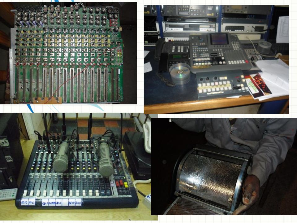
There are three TV studios and one FM studio at OSRC . signal generation starts from the various studios. Each studio is divided into two sub- sections both in the FM and TV sections; CONTINUITY STUDIO CONTROL ROOM in the continuity studio, I engaged in carrying out continuity tests on the microphone (the neck and table micro phones), adjusting TV studio lightings in other to eliminate object shadows using a lighting console. In the control room I engaged in graphics and animation making for news and other programs and signal sharing between the two studios (with the help of a televiser and a master controller) I was appointed the sound engineer. I fixed the adjustment knobs (channel faders and audio equaliser) of the TV studios’ audio console
, adjusting TV studio lightings in other to eliminate object shadows using a lighting console. In the control room I engaged in graphics and animation making for news and other programs and signal sharing between the two studios (with the help of a televiser and a master controller) I was appointed the sound engineer. I fixed the adjustment knobs (channel faders and audio equaliser) of the TV studios’ audio console.")
8
Mode of signal generation and transfer
The microphones receives voice signals and converts it to electrical (electronic) signal; the TV studio cameras capture graphic positions and converts it to electronic signals. The output of the microphones and cameras are fed as inputs into the audio and video console (mixer) respectively by means of coaxial cables. Also, video and audio signals from DVD players, CD players and VHS are also fed respectively into the consoles. The output of the audio and video console is fed into various monitoring devices, distribution amplifiers and circuitry conversions on the P.I.E (Program Input Equipment) Keep it brief. Make your text as brief as possible to maintain a larger font size.
 signal; the TV studio cameras capture graphic positions and converts it to electronic signals. The output of the microphones and cameras are fed as inputs into the audio and video console (mixer) respectively by means of coaxial cables. Also, video and audio signals from DVD players, CD players and VHS are also fed respectively into the consoles. The output of the audio and video console is fed into various monitoring devices, distribution amplifiers and circuitry conversions on the P.I.E (Program Input Equipment) Keep it brief. Make your text as brief as possible to maintain a larger font size.")
9
TV CONTROL ROOM (simplified block)
PROGRAMMED INPUT EQUIPMENT VIDEO DISTRIBUTION CIRCUIT Monitors (TV sets) camera VIDEO DISTRIBUTION AMPLIFIER VIDEO MIXER SOME WAVE MONITORING DEVICES AUDIO DISTRIBUTION CIRCUIT Playback devices AUDIO CONSOLE AUDIO DISTRIBUTION AMPLIFIER Use a section header for each of the topics, so there is a clear transition to the audience. microphones SOME WAVE MONITORING DEVICES In-house speakers OPTIC FIBRE SYSTEM To transmitter
 camera. VIDEO DISTRIBUTION AMPLIFIER. VIDEO MIXER. SOME WAVE MONITORING DEVICES. AUDIO DISTRIBUTION CIRCUIT. Playback devices. AUDIO CONSOLE. AUDIO DISTRIBUTION AMPLIFIER. Use a section header for each of the topics, so there is a clear transition to the audience. microphones. SOME WAVE MONITORING DEVICES. In-house speakers. OPTIC FIBRE SYSTEM. To transmitter.")
10
WORK CARRIED OUT IN TRANSMITTER SECTION
Observing the switching on and shutting down process of the Harris transmitter 1 Fault detection through meter readings and colour change 2 Signal flow from the transmitter to the antenna 3 This is another option for an Overview slide.

11
Microsoft Engineering Excellence
Opening formalities of the TV transmitter as part of work done (sigma HD 3050P1 Harris Transmitter) Putting on the Harris transmitter occurs at about 6:30 am. The Townsend transmitter on the other hand is operated from 10 pm to 12midnight. The switching on/off of the Harris transmitter is similar to that of the Townsend. Immediately the 810kva generator is powered on, all the lightings of the transmitter room is first switched on to aid illumination. The 3.5 tons and 7.5 tons air condition is powered on. This provides the air cooling of the transmitter components. The dehydrator is then switched on to suck out any residual liquid or moisture from the base of the antenna to prevent reflected power when the transmitter goes on beam. The TV main power supply is powered on which triggers on the surge suppressor. The AVR is energised (a terminology for switching on ) If there is relevant video content, such as a case study video, demo of a product, or other training materials, include it in the presentation as well. Microsoft Confidential
 Putting on the Harris transmitter occurs at about 6:30 am. The Townsend transmitter on the other hand is operated from 10 pm to 12midnight. The switching on/off of the Harris transmitter is similar to that of the Townsend. Immediately the 810kva generator is powered on, all the lightings of the transmitter room is first switched on to aid illumination. The 3.5 tons and 7.5 tons air condition is powered on. This provides the air cooling of the transmitter components. The dehydrator is then switched on to suck out any residual liquid or moisture from the base of the antenna to prevent reflected power when the transmitter goes on beam. The TV main power supply is powered on which triggers on the surge suppressor. The AVR is energised (a terminology for switching on ) If there is relevant video content, such as a case study video, demo of a product, or other training materials, include it in the presentation as well. Microsoft Confidential.")
12
The PIE control button switches on all equipment on the rack.
A knob at the back of the transmitter (power knob) is turned from 0 to 1 (as indicated) and the earth switch is removed. The standby button located at the front of the transmitter is pressed down. This places the transmitter on filament voltage (this voltage heats up/warms the cathode plate of the IOT) We then wait for about five minutes before the transmitter goes on beam voltage (33kV dc). The PIE control button switches on all equipment on the rack. At this point, we await signals from the studio. While we await signal reception, a tone and colour bar can be generated right there in the transmitter using the tone and colour bar generator. This overrides any signal from the studio. When the audio/visual signal arrives, the tone and colour bar is disconnected and the incoming signal is beamed to the wider audience. Add a case study or class simulation to encourage discussion and apply lessons.
 is turned from 0 to 1 (as indicated) and the earth switch is removed. The standby button located at the front of the transmitter is pressed down. This places the transmitter on filament voltage (this voltage heats up/warms the cathode plate of the IOT) We then wait for about five minutes before the transmitter goes on beam voltage (33kV dc). The PIE control button switches on all equipment on the rack. At this point, we await signals from the studio. While we await signal reception, a tone and colour bar can be generated right there in the transmitter using the tone and colour bar generator. This overrides any signal from the studio. When the audio/visual signal arrives, the tone and colour bar is disconnected and the incoming signal is beamed to the wider audience. Add a case study or class simulation to encourage discussion and apply lessons.")
13
Fault detection and prevention on the transmitter
Discuss outcomes of the case study or class simulation. Cover best practices. FM Harris HT 35/30CD Transmitter

14
Microsoft Engineering Excellence
SIGNAL TRANSMISSION FROM TRANSMITTER TO ANTENNA Microsoft Confidential

15
Microsoft Engineering Excellence
CONCLUSION The SIWES program has afforded me the opportunity to broaden my understanding of communication regarding my profession. It opened me up to solve problems, Interact and share practical knowledge with students from other institutions of higher learning. Is your presentation as crisp as possible? Consider moving extra content to the appendix. Use appendix slides to store content that you might want to refer to during the Question slide or that may be useful for attendees to investigate deeper in the future. Microsoft Confidential

16
RECOMMENDATIONS The university should be involved in the direct placement of students (if not all but for some students) as this will reduce student loitering about looking for SIWES placement A single visit/inspection by the supervisors from the university is not enough. A regular visit will install seriousness in the student and the company where he/she has been posted to. Students on the other hand should endeavour to get experience instead of looking for places of higher pay. (knowledge is what generates wealth).
 as this will reduce student loitering about looking for SIWES placement. A single visit/inspection by the supervisors from the university is not enough. A regular visit will install seriousness in the student and the company where he/she has been posted to. Students on the other hand should endeavour to get experience instead of looking for places of higher pay. (knowledge is what generates wealth).")
17
THANK YOU FOR LISTENING
Microsoft Engineering Excellence THANK YOU FOR LISTENING Is your presentation as crisp as possible? Consider moving extra content to the appendix. Use appendix slides to store content that you might want to refer to during the Question slide or that may be useful for attendees to investigate deeper in the future. Microsoft Confidential

Similar presentations


>")


Presented by ABC.>")
