Download presentation
Presentation is loading. Please wait.

1
Monica Stoica, Boston University Smonica@cs.bu.edu
Chapter 15 Cyganski Book Monica Stoica, Boston University

2
Wire as transmission mediums
Wire was the original medium for the electronic transmission of information; today it is still the most common and versatile medium. transmission systems can involve both guided and unguided movement of electro magnetic waves. The wire-based transmission scheme guides electro magnetic waves, either between a pair of separate wires, or inside a coaxial arrangement. A coaxial cable (often called coax for short) has both a ``center'' conductor and a second ``shield'' conductor. These conductors are separated by some insulating material, such that the shield conductor entirely surrounds the center conductor.
 has both a ``center conductor and a second ``shield conductor. These conductors are separated by some insulating material, such that the shield conductor entirely surrounds the center conductor.")
3
Cables In the case of noncoaxial transmission, the pair of wires may be held either parallel to each other by an appropriate stiff insulating material, or individually insulated and twisted around each other. Finally, some arrangement of surrounding shield conductor may be placed around the resulting twisted pair to form a shielded twisted pair (STP). Implicit in this construction is that the physical arrangement of the shield conductor is not nearly as accurate as in the construction of coax. The unshielded twisted pair is called TP or often UTP to distinguish it clearly from STP. All of the above wire-based transmission media are called cables, not just the coaxial cable.
. Implicit in this construction is that the physical arrangement of the shield conductor is not nearly as accurate as in the construction of coax. The unshielded twisted pair is called TP or often UTP to distinguish it clearly from STP. All of the above wire-based transmission media are called cables, not just the coaxial cable.")
5
Cost of cables The cost of a cable is a function of the cost of the materials and the manufacturing process. Thus, cables with larger diameter,involving more copper conductor and more insulation, are more expensive than those with small diameter. Likewise, cables that have twisted pairs of conductors are more expensive than those that do not, while STP is more expensive,and coaxial is even more so . This of course leads to the question:why not use the smallest, simplest cable for all applications?

7
E&M a cable moves electro magnetic (E&M) waves by providing a channel in which the pair of conductors act like a pair of mirrors between which the wave bounces back and forth until it reaches its destination. To be precise, E&M waves may be confined in such as way that they can traverse the cable moving parallel to these conductors, that is without bouncing, yet still interacting with the conductors. The E&M wave interacts with the free electrons in the conductors, which are responsible for the guiding of this wave.
 waves by providing a channel in which the pair of conductors act like a pair of mirrors between which the wave bounces back and forth until it reaches its destination. To be precise, E&M waves may be confined in such as way that they can traverse the cable moving parallel to these conductors, that is without bouncing, yet still interacting with the conductors. The E&M wave interacts with the free electrons in the conductors, which are responsible for the guiding of this wave.")
8
E&M Think of these electrons, which are free to move within the conductor but confined there, as ball bearings,and think of the E&M wave as a package of energy riding on those ball bearings, guided to its destination by the shape of the conductor that holds the ball bearings. Now, no one can make a perfectly frictionless ball bearing! So, we would expect in this analogous system that our package would eventually slow down and stop on the conveyer if it offers no other source of energy for the packages.

9
Speed The electrons in our conductor also are subject to a friction-like energy loss mechanism that we call resistance. However, in our case, our E&M energy packages act a little differently.By the theory of special relativity, our E&M packages (which are made of the elementary particles called photons) cannot slow down! They must travel at the speed of light. But because our packages ``are'' energy, they themselves can be consumed to provide the power needed to sustain their speed in the face of the losses due to the electrons. In effect, our electron ball bearings are eating away the package as it moves along.
 cannot slow down! They must travel at the speed of light. But because our packages ``are energy, they themselves can be consumed to provide the power needed to sustain their speed in the face of the losses due to the electrons. In effect, our electron ball bearings are eating away the package as it moves along.")
10
At the end of our trip, any pulses of E&M energy we have transmitted will be found to be smaller in size. Or, in terms of the kinds of graphs of light intensity or voltage and current we have been using throughout the preceding chapters, the height of all the transmitted pulses will be reduced. We call this loss of energy and related reduction in the size of transmitted pulses attenuation. As you might suspect, the longer the cable that we are using, the greater the attenuation. On the other hand, the larger the conductors we use, the less this attenuation will become, up to some limit. Hence, larger, more expensive cables will have less attenuation and be more desirable if this attenuation has negative effects on our ability to move information.

11
Willingness to pay Because we will still be dealing with the problem of noise that is determined by the temperature of the receiving system at the far end, the reduction in the size of our pulses directly reduces the rate at which we can transmit information over a certain cable. In the next slide we see typical attenuation figures for various cables. These figures alone explain the willingness to pay more for STP and still more for coaxial cable in applications that require the highest information transmission rates.

13
Why some cables are better than others
While the previous section explained the desirability of some cables owing to their low attenuation characteristics, it did not explain why they possess these different characteristics other than with respect to behavior versus conductor size. Here we will discuss the role of the ``geometry'' of the cable. In a vacuum, each of the above cables would perform nearly as well as the others. However, cables tend to be routed next to each other, and near other metallic objects and generators of E&M energies. The ``open'' nature of untwisted cable presents a problem in that nearby conductors can steal some of the energy that it carries and can insert unwanted E&M noise.

14
UTP, STP UTP cable still is subject to the loss problem but is less affected by noise pickup because the twists cause interfering pickup signals to cancel themselves when picked up inside of adjacent twists! STP reduces the losses by better confining the E&M to the inside of the shield. The coaxial cable, because of the complete confinement of the E&M wave, is not subject to the level of loss and noise problems found in other wired cables. Furthermore, because its geometry is very tightly held in position, the signal itself undergoes less distortion in shape while traversing it. In a very rough extension of our analogy of the last section, we can think of the coax as presenting very well manufactured mirrors for the transport of our signal, versus warped mirrors in the case of STP.

15
Parallel Conductor Cable Application
While parallel conductor cable is used extensively for power delivery, about the only signal-carrying application you will find this cable being used to support is as the short extension cord leading from your telephone wall plug to the telephone itself. The short distance and small bandwidth of the signal involved allow use in this application, in which the flat nature of the cable makes it more attractive to the eye in its very visible role.

16
UTP Applications UTP cable is found extensively in the so-called local loop of the telephone company. The local loop is that wiring that connects your house to the telephone company's local``switch'' building. This cable is typically under 18,000 feet in length and suffices for transmission of telephone signals. New kinds of special digital modems for ISDN and XDSL data services can sometimes (depending upon the length and nearby interfering sources) be used to move data at higher speeds than a telephone-signal-based modem. For example 128 kbps (ISDN, bidirectional) to Mbps (HDSL in one direction) can be achieved using (now) relatively low cost and very sophisticated special connection devices.
 be used to move data at higher speeds than a telephone-signal-based modem. For example 128 kbps (ISDN, bidirectional) to Mbps (HDSL in one direction) can be achieved using (now) relatively low cost and very sophisticated special connection devices.")
17
UTP Rates as high as 52 Mbps (VDSL in one direction) can be obtained if the length of the local loop is below 3,280 feet. The telephone companies also make extensive use of UTP for movement of digitized groups of voice signals between their switching stations. The T1 signal unidirectionally carries groups of 24 voice channels in a Mbps digital format over 6,000 foot distances between regenerator circuits. is also found in the walls (in spaces called plenums) throughout most buildings. It is used to complete the local loop from the building entrance to the telephone wall plates in the rooms.
 throughout most buildings. It is used to complete the local loop from the building entrance to the telephone wall plates in the rooms.")
18
More UTP UTP has found extensive use as a cheap medium for the distribution of medium-speed computer network data connectivity. Ethernet data is routinely transmitted in a signaling system known as 10 Base-T Ethernet in which UTP cable is used for distances up to 100 m(328 feet). UTP can be made with a variety of materials, sizes of conductors,and numbers of pairs inside a single cable. A particularly high quality UTP is called UTP-5. This cable type has been used to support 100 Mbps Ethernet transmissions over distances of 100 m.
. UTP can be made with a variety of materials, sizes of conductors,and numbers of pairs inside a single cable. A particularly high quality UTP is called UTP-5. This cable type has been used to support 100 Mbps Ethernet transmissions over distances of 100 m.")
19
STP Applications STP is used to some extent by telephone companies for moving groups (96) of digitized telephone conversations over distances of 6,000 feet between ``repeaters'' that receive and retransmit the signal for the next such hop, to span the distance of several miles between telephone company switching stations. The so-called T2 connection involves digital data transmission at speeds of Mbps. High-quality STP has been applied by the telephone companies for transmission rates as high as Mbps in Europe.
 of digitized telephone conversations over distances of 6,000 feet between ``repeaters that receive and retransmit the signal for the next such hop, to span the distance of several miles between telephone company switching stations. The so-called T2 connection involves digital data transmission at speeds of Mbps. High-quality STP has been applied by the telephone companies for transmission rates as high as Mbps in Europe.")
20
Coaxial Cable Applications
coaxial cable is used wherever there exists a need for long-distance, low-attenuation, and low-noise transmission of information. Probably everyone is familiar with the use of coaxial cable for the transmission of a hundred TV channels into the home via CATV coaxial cable, because 70% of all homes in the United States have CATV service. These cables provide a bandwidth of nearly 1 GHz (that is, 1,000 MHz) into the home. These same cables are capable of transmitting many Gbps of information into those same homes. In fact, the research and test deployment of CATV-based Internet delivery systems is currently a growth industry.
 into the home. These same cables are capable of transmitting many Gbps of information into those same homes. In fact, the research and test deployment of CATV-based Internet delivery systems is currently a growth industry.")
21
Coaxial Cable Until recently, coaxial cable has been the major delivery system for 10 and 100 Mbps Ethernet computer network data signals, for hop distances of 500 m (1,640 ft) and 185 m (607 ft), respectively, for the larger and smaller diameter cables. Coaxial cable for this purpose is being rapidly supplanted by UTP cable. The telephone companies also resort to coaxial cable to bridge larger distances with higher-rate digital connections. One example is the use of coaxial cable to transmit 140 Mbps data signals between telephone switch buildings with a hop distance of up to 2 km (6,562 ft).
 and 185 m (607 ft), respectively, for the larger and smaller diameter cables. Coaxial cable for this purpose is being rapidly supplanted by UTP cable. The telephone companies also resort to coaxial cable to bridge larger distances with higher-rate digital connections. One example is the use of coaxial cable to transmit 140 Mbps data signals between telephone switch buildings with a hop distance of up to 2 km (6,562 ft).")
22
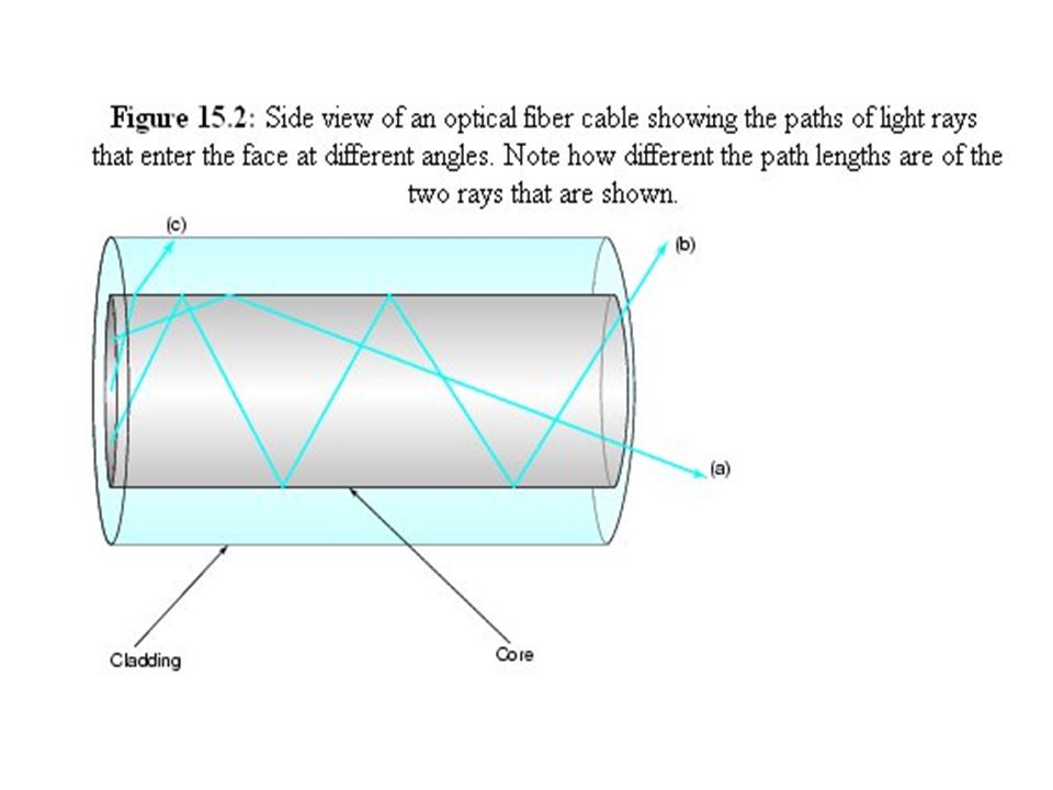
Fiber Optic Cable The means of guiding an E&M wave as in the fiber optic cable has an immense advantage over the use of wire-based wave guides: this system does not depend upon the quality (low resistance) of the conductors to obtain low attenuation propagation of the E&M wave. In fact, the reflecting surface of the waveguide is formed by the surface of an insulator.In effect the boundary between two layers of glass or plastic (the core and cladding of the fiber) acts as an ideal (no loss) mirror. The mirror behavior of this boundary derives from a property of such boundaries and E&M waves that strike them at shallow angles.
 of the conductors to obtain low attenuation propagation of the E&M wave. In fact, the reflecting surface of the waveguide is formed by the surface of an insulator.In effect the boundary between two layers of glass or plastic (the core and cladding of the fiber) acts as an ideal (no loss) mirror. The mirror behavior of this boundary derives from a property of such boundaries and E&M waves that strike them at shallow angles.")
24
Fiber Optic If an E&M wave strikes such a boundary at an angle below the ``critical angle'' it undergoes ``total internal reflection.'' You may be familiar with this phenomenon as it can be seen in operation by looking at the bottom side of the water-air boundary at the top of an aquarium from a position at the side of the glass enclosure. If your eye is near enough to the boundary, you see an exceedingly clear mirror view of the scene out the other side of the aquarium. Thus, the attenuation of a fiber-optic cable is essentially only dependent upon the clarity of the optical material used in the core, and exceedingly high clarities have been achieved.

25
Other benefits of the fiber optic
The total confinement of the E&M wave means that surrounding materials do not increase the attenuation of the wave. Because there are no free electrons as would be found in a conductor-based cable, no interference can be generated even by large surrounding magnetic fields. Being an insulator, the fiber insulates the connected systems from each other. This is a major factor in cable systems in which atmospheric potentials and ground potentials can cause interfering and sometimes destructive currents to flow parasitic ally along communication cables. For a given attenuation, a fiber cable is exceedingly lightweight and small in diameter. This means that many fibers may be placed in a cable where once only one wire-based cable may have been possible.

26
Properties of fiber optic
Relatively low cost fiber-optic cable available off-the-shelf today exhibits attenuations of less than 0.5 dB/1,000 ft while offering usable bandwidths of hundreds of MHz. A cable exhibiting these characteristics containing four separate fibers, for example, could be purchased in 1999 for under $1.50/foot. Compare this attenuation and cost with that of even high grade coaxial line. Higher cost fiber cables that achieve as little as 0.03 dB/1,000 ft attenuations and usable bandwidths in excess of 1 Tbps (1 Tera bps = 1,000,000 Mbps) have also been constructed.
 have also been constructed.")
27
Amplifiers A new technology is rapidly coming into commercial application and is revolutionizing the long-distance fiber-optic transmission of data. By adding a small amount of Erbium additive to a fiber during its manufacture, it is possible to turn the fiber itself into a laser amplification system! By simply passing an optical signal through a short piece of Erbium-doped fiber (typically 10 m) and pumping that length with light from another laser, the optical signal will be strengthened and can be returned to its original levels without ever leaving the fiber-optic cable for separate electronic processing. The Erbium-doped fiber amplifier (EDFA) is being incorporated in all of the newest transoceanic cable runs to interconnect the continents with very high-speed, low-maintenance, data service.
 and pumping that length with light from another laser, the optical signal will be strengthened and can be returned to its original levels without ever leaving the fiber-optic cable for separate electronic processing. The Erbium-doped fiber amplifier (EDFA) is being incorporated in all of the newest transoceanic cable runs to interconnect the continents with very high-speed, low-maintenance, data service.")
28
Examples For example, a transoceanic cable from the United States to England that uses EDFA technology was completed in September of 1996. This cable holds four fibers each providing 2.5 Gbps of data service,for a total of 10 Gbps of data. It is anticipated that the achievable data rates can be increased by improved methods of signaling and upgrades that will bring each fiber's bit rate to 20 Gbps or greater. Prior to deployment of this cable, the connection was served by a fiber-optic cable, deployed in 1988, which used electronic repeaters and provided a total of 280 Mbps of data service. Thanks to the immutable under sea electronic repeaters, no upgrades in data rates were possible despite significant new capabilities in fiber transmission and reception systems since that time.

29
Solutions A remarkable property of special materials has been discovered that promises to have an impact like that of the EDFA on the speeds and distances achievable with fiber-optic cables. A soliton is a special packet of optical energy within such a cable that does not ``disperse'' , it is immune to the low-pass phenomenon that we have previously said characterizes all physical systems that transmit waves. Thus, a fiber using soliton transmission can achieve fantastic data rates over large distances. Nippon Telephone of Japan, has demonstrated soliton transmission of a 10 Gbps data stream over a distance of 50,000 km (over 30,000 miles). Laboratory tests show that soliton technology may provide data rates in excess of 1 Tbps (1012 bps, or 1 million megabits per second) in the future over transcontinental and inter continental distances.
. Laboratory tests show that soliton technology may provide data rates in excess of 1 Tbps (1012 bps, or 1 million megabits per second) in the future over transcontinental and inter continental distances.")
Similar presentations


 Nouf Aljaffan1. 2 3.>")


 carries signals of higher frequency ranges than those in twisted pair cable, in part because the two media are constructed.>")


