Download presentation
Presentation is loading. Please wait.

1
PummelCo Impacting Your World

2
PummelCo is: From left to right: Beaudy Sheckler Jacob McGrew Tim Burkhard Benjamin Shell From left to right: Beaudy Sheckler Jacob McGrew Tim Burkhard Benjamin Shell

3
Mission Statement A mechanical device capable of hurling large objects over long distances to the dismay of civil engineers.

4
Introduction PummelCo is a team consisting of Beaudy Sheckler, Ben Shell, Jacob McGrew, and Tim Burkhard. The decision regarding what product we were to design was perhaps the most time- consuming of our determinations, hinging on a variety of factors. A project worthy to be undertaken by PummelCo for ME 118 would have to be simple enough to complete in the allotted time period, yet interesting enough to set us apart from the other groups. In the end we decided to build a gigantic trebuchet, capable of throwing a small automobile, for our term project. We call this trebuchet the Colossus.

5
Introduction (cont.) A trebuchet is a mechanical device used by medieval armies to destroy the walls of enemy castles, and by modern hobbyists to throw projectiles long distances. A trebuchet is identical to a simple catapult but for its launching mechanism. While a catapult uses a basket or similar cradle-like feature attached to the end of its arm for the initial acceleration of the projectile, a trebuchet utilizes an additional mechanical advantage by fixing a cable or rope in place of the basket, which is in turn attached to the projectile. The rope creates a whipping action that results in an enormous rotational velocity in the projectile which is then transmitted to linear motion when the rope slips away from the arm.

6
Introduction (cont.) The process of using a trebuchet is similar to that of a catapult, consisting of three steps: loading the projectile, creating potential energy, and triggering the weapon. A suitable projectile for a trebuchet must have a rope or cable attached to it. The projectile is set underneath the trebuchet, and a loop in its rope slipped over a hook on the end of the arm. Potential energy is usually stored in a trebuchet through the use of weights attached to the arm opposite the projectile. These weights are lifted to their loaded position and held by some triggering mechanism. The trebuchet can be triggered by cutting a rope holding the weights up, or by pulling a trigger rope to activate the machine.

7
Early Solutions

8
Early Designs Continued

9
Modern Redesigns

10
Customer Requirements Durable Stylish Transportable – break down into small parts Great performance – throwing heavy objects over long distances Affordable Quick and easy reloading Room for corporate advertising Compatible with accessories Serviceable Capable of throwing various objects – including logs, rocks Safe to operate Precision and accuracy Durable Stylish Transportable – break down into small parts Great performance – throwing heavy objects over long distances Affordable Quick and easy reloading Room for corporate advertising Compatible with accessories Serviceable Capable of throwing various objects – including logs, rocks Safe to operate Precision and accuracy

11
Brainstorming

12
Quality Function Deployment (QFD)
")
13
Concept: Bent Arm

14
Concept: Flywheel

15
Concept: Pivot Arm

16
Concept: Traditional

17
Concept: Floating Arm

18
Concept: Scissor

19
Concept: Screw

20
Concept: Cam Pulley

21
Gantt Chart

22
Concept Screening

23
AHP: Efficiency

24
AHP: Simplicity

25
AHP: Usability

26
AHP: Style

27
AHP: Criteria vs. Criteria

28
AHP: Overall Priority Final Concept Selection: Floating Arm Trebuchet

29
Design For Manufacturing The PummelCo Colossus is designed to be built using commercially available materials, largely consisting of extruded I-beams. The extruded pieces will be welded together, and the entire truss will be fixed to a rotating base in order to easily aim it. The wheels and rails are available from major railroad manufacturers. The most time- consuming portion of manufacturing the Colossus will be assembling the frame. However, the Colossus can be sold as a kit, complete with all extruded materials and parts necessary to build the Colossus. The buyer can assemble the machine on site.

30
FMEA: Arm Stress Fracture Causes- Improper use, material fatigue Effects- Danger to user, failure to launch, disappointing performance Likelihood- 3 Severity- 7 Detecting- 1 RPN- 21 Corrosion Causes- Exposure to environment Effects- Embrittlement of assembly Likelihood- 1 Severity- 1 Detecting- 1 RPN- 1 Stress Fracture Causes- Improper use, material fatigue Effects- Danger to user, failure to launch, disappointing performance Likelihood- 3 Severity- 7 Detecting- 1 RPN- 21 Corrosion Causes- Exposure to environment Effects- Embrittlement of assembly Likelihood- 1 Severity- 1 Detecting- 1 RPN- 1

31
FMEA: Water Tanks (Weights) Corrosion Causes- Exposure to environment, improper use Effects- Leaky tanks Likelihood- 3 Severity- 2 Detecting- 1 RPN- 6 Stress Fracture Causes- Improper use, material fatigue Effects- Leaky tanks Likelihood- 4 Severity- 2 Detecting- 1 RPN- 8 Corrosion Causes- Exposure to environment, improper use Effects- Leaky tanks Likelihood- 3 Severity- 2 Detecting- 1 RPN- 6 Stress Fracture Causes- Improper use, material fatigue Effects- Leaky tanks Likelihood- 4 Severity- 2 Detecting- 1 RPN- 8
 Corrosion Causes- Exposure to environment, improper use Effects- Leaky tanks Likelihood- 3 Severity- 2 Detecting- 1 RPN- 6 Stress Fracture Causes- Improper use, material fatigue Effects- Leaky tanks Likelihood- 4 Severity- 2 Detecting- 1 RPN- 8 Corrosion Causes- Exposure to environment, improper use Effects- Leaky tanks Likelihood- 3 Severity- 2 Detecting- 1 RPN- 6 Stress Fracture Causes- Improper use, material fatigue Effects- Leaky tanks Likelihood- 4 Severity- 2 Detecting- 1 RPN- 8")
32
FMEA: Hook Stress Fracture Causes- Improper use, material fatigue Effects- Danger to property and user, nullification of utility Likelihood- 3 Severity- 3 Detecting- 1 RPN- 9 Corrosion Causes- Exposure to environment Effects- Embrittlement of assembly Likelihood- 2 Severity- 3 Detecting- 1 RPN- 6 Stress Fracture Causes- Improper use, material fatigue Effects- Danger to property and user, nullification of utility Likelihood- 3 Severity- 3 Detecting- 1 RPN- 9 Corrosion Causes- Exposure to environment Effects- Embrittlement of assembly Likelihood- 2 Severity- 3 Detecting- 1 RPN- 6

33
FMEA: Axles Lack of lubrication Causes- Improper use Effects- Cessation of wheels Likelihood- 1 Severity- 2 Detecting- 1 RPN- 2 Stress Fracture Causes- Improper use, material fatigue Effects- Danger to user Likelihood- 2 Severity- 3 Detecting- 1 RPN- 6 Corrosion Causes- Exposure to environment Effects- Embrittlement of assembly Likelihood- 2 Severity- 2 Detecting- 1 RPN- 4 Lack of lubrication Causes- Improper use Effects- Cessation of wheels Likelihood- 1 Severity- 2 Detecting- 1 RPN- 2 Stress Fracture Causes- Improper use, material fatigue Effects- Danger to user Likelihood- 2 Severity- 3 Detecting- 1 RPN- 6 Corrosion Causes- Exposure to environment Effects- Embrittlement of assembly Likelihood- 2 Severity- 2 Detecting- 1 RPN- 4

34
FMEA: Main Truss Stress Fracture Causes- Improper use, material fatigue Effects- Danger to user Likelihood- 3 Severity- 3 Detecting- 1 RPN- 9 Corrosion Causes- Exposure to environment Effects- Embrittlement of assembly Likelihood- 1 Severity- 1 Detecting- 1 RPN- 1 Stress Fracture Causes- Improper use, material fatigue Effects- Danger to user Likelihood- 3 Severity- 3 Detecting- 1 RPN- 9 Corrosion Causes- Exposure to environment Effects- Embrittlement of assembly Likelihood- 1 Severity- 1 Detecting- 1 RPN- 1

35
FMEA: Trigger Mechanism Stress Fracture Causes- Improper use, material fatigue Effects- Unintended operation, danger to user Likelihood- 1 Severity- 5 Detecting- 1 RPN- 5 Corrosion Causes- Exposure to environment Effects- Unintended operation, danger to user Likelihood- 1 Severity- 1 Detecting- 1 RPN- 1 Stress Fracture Causes- Improper use, material fatigue Effects- Unintended operation, danger to user Likelihood- 1 Severity- 5 Detecting- 1 RPN- 5 Corrosion Causes- Exposure to environment Effects- Unintended operation, danger to user Likelihood- 1 Severity- 1 Detecting- 1 RPN- 1

36
FMEA: Vertical Track Lack of lubrication Causes- Improper use Effects- Cessation of wheels Likelihood- 1 Severity- 1 Detecting- 1 RPN- 1 Corrosion Causes- Exposure to environment Effects- Embrittlement of assembly Likelihood- 1 Severity- 2 Detecting- 1 RPN- 2 Lack of lubrication Causes- Improper use Effects- Cessation of wheels Likelihood- 1 Severity- 1 Detecting- 1 RPN- 1 Corrosion Causes- Exposure to environment Effects- Embrittlement of assembly Likelihood- 1 Severity- 2 Detecting- 1 RPN- 2

37
FMEA: Horizontal Track Stress Fracture Causes- Improper use, material fatigue Effects- Danger to user Likelihood- 2 Severity- 3 Detecting- 1 RPN- 6 Stress Fracture Causes- Improper use, material fatigue Effects- Danger to user Likelihood- 2 Severity- 3 Detecting- 1 RPN- 6

38
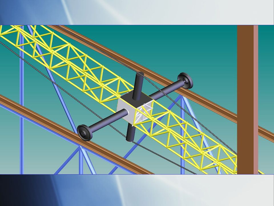
Detail Drawing

39
Tolerance Analysis Axle: MMC=7.998" LMC=7.996" Bushing: MMC=8.000" LMC=8.003" Worst Case: Max Clearance=.007" Min Clearance=.002" _____________________ Weights: MMC=11.998" LMC=12.000" Bushing: MMC=12.005" LMC=12.001 Worst Case: Max Interference=.007" Min Interference=.001" Axle: MMC=7.998" LMC=7.996" Bushing: MMC=8.000" LMC=8.003" Worst Case: Max Clearance=.007" Min Clearance=.002" _____________________ Weights: MMC=11.998" LMC=12.000" Bushing: MMC=12.005" LMC=12.001 Worst Case: Max Interference=.007" Min Interference=.001"

40
Solidworks Screenshots

44
Solidworks Model Simulation Video removed from the CD-ROM version of this presentation. To watch the simulation, please open PummelCo-Solidworks.avi from the media folder on the CD.

45
Summary & Conclusion In designing the Colossus, we utilized many of the concepts learned in ME 118. As the first step of our design process, we created a Gantt chart using Microsoft Project, which we referred to when delegating tasks and approaching each progressive objective. We then had a series of brainstorming sessions designed to facilitate a flow of creativity, to develop a repertoire of effective ideas for our trebuchet concept, and to build a team capable of producing a more than satisfactory product. After we had a large collection of vague concepts for the Colossus came the task of weeding them out. We decided that the trebuchet would be powered by falling weights to minimize energy loss and maximize efficiency, which eliminated many of our ideas. We made freehand sketches of the remaining concept designs and began researching them. We decided to stick to a concept that had been used by previous trebuchet designers in order to ensure the credibility of that design. Due to considerations of simplicity and efficiency, we settled on a standard floating arm style trebuchet. This style reduces much of the structural stress while reducing energy loss and maintaining a simplistic design.

46
Summary & Conclusion (cont.) The detail design of our trebuchet was very time consuming, since there were many portions of the machine which would have to come together in order to ensure that the machine would operate correctly. We had to weigh the costs and benefits of adhering to certain customer requirements, which meant disregarding some of them. Through the use of heavy duty materials and strong bonding processes, the Colossus will easily meet the durability requirement (more on this is discussed in FMEA). Of course, the trebuchet meets the stylishness requirement through its shear power. Through extensive internet research and computer simulation, we found that it would be nearly impossible to meet our most important customer requirement (that the Colossus be capable of launching a small vehicle) while creating a mobile trebuchet. After much deliberation, we decided to scrap the mobility requirement in order to create a powerful machine. Considering the size and capabilities of the Colossus, it is relatively affordable, and will be more so considering its standardized construction.
. Of course, the trebuchet meets the stylishness requirement through its shear power. Through extensive internet research and computer simulation, we found that it would be nearly impossible to meet our most important customer requirement (that the Colossus be capable of launching a small vehicle) while creating a mobile trebuchet. After much deliberation, we decided to scrap the mobility requirement in order to create a powerful machine. Considering the size and capabilities of the Colossus, it is relatively affordable, and will be more so considering its standardized construction..")
47
Summary & Conclusion (cont.) PummelCo is particularly proud of its approach to the easy to reload requirement. The Colossus will utilize large water tanks as counterweights. That way, the customer may simply pump water into the tanks after they have already been raised to their loaded position. If the Colossus is strategically placed near high population density areas such as freeways and water parks, corporate billboards can be easily placed upon its large vertical channels. As a result, the Colossus can be advertised as an effective promotional tool. For example, car dealerships may hold car launching events to demonstrate the inferiority of their competition. There are many accessories that can be designed and sold with the Colossus, such as specially designed projectiles and replacement launching cables. Upgrades can be made available, including larger diameter axles and wheels, stronger water tanks, and a more efficient triggering mechanism. Since the Colossus is constructed entirely of commercially available materials, a user may service their own trebuchet, or purchase precut I- beams or railroad portions to install on their trebuchet. Though there will always be an inherent danger in using large medieval siege engines, PummelCo was careful to make safety the foremost design consideration, as shown in our extensive FMEA analysis.

48
Summary & Conclusion (cont.) The FMEA analysis we performed on the Colossus revealed the need for weatherproofing. As a solution to this problem, PummelCo implemented a painting system similar to that of an automobile. For the smaller parts, such as the hook, the Colossus will use stainless steel. The process of designing a device of this magnitude can be a daunting one. In hindsight our team probably spent too much time in deciding which design to go with which left us with less design time then would have been desired. The modeling process was also a project that proved to be more time consuming than we had planned. For Colossus II and all further PummelCo products we will use a more realistic approach which will draw on the experiences of the Colossus I design. Overall, we have had an enjoyable learning experience, which will help us in our future careers. The FMEA analysis we performed on the Colossus revealed the need for weatherproofing. As a solution to this problem, PummelCo implemented a painting system similar to that of an automobile. For the smaller parts, such as the hook, the Colossus will use stainless steel. The process of designing a device of this magnitude can be a daunting one. In hindsight our team probably spent too much time in deciding which design to go with which left us with less design time then would have been desired. The modeling process was also a project that proved to be more time consuming than we had planned. For Colossus II and all further PummelCo products we will use a more realistic approach which will draw on the experiences of the Colossus I design. Overall, we have had an enjoyable learning experience, which will help us in our future careers.

49
Project Marketing

50
Video removed from the CD-ROM version of this presentation. To watch the commercial, please go to the commercial category from the main menu on the CD. Commercial

51
Q & A This Castle Has been Pummeled

Similar presentations


 transmits the drive from the differential sun wheel to the rear hub. The arrangement of a simple rear axle can be seen in.>")


