Download presentation
Presentation is loading. Please wait.

1
Comparison Of Network On Chip Topologies Ahmet Salih BÜYÜKKAYHAN 2007706435 - 2009 Fall

2
OUTLINE Introduction Basic Definitions Properties of a Topology NOC Topologies Evaluation Conclusion

3
Introduction to NOC NOC A micronetwork of components Transfers information between nodes Challenges Performance requirements Latency as small as possible As many concurent transfers as possible Tight energy boundaries Reliability requirements Low Cost

4
NOC Motivation Moores Law, doubling the number of gates every18 months by shrinking the technology dimensions wire dimensions resistance (R= L/A) inter-wire spacing capacitance (C = ε o A/d) Require the periodic insertion of repeaters Consume more dynamic and leakage power 50% of the power dissipation is due to the (long) wires.[1]
![NOC Motivation Moores Law, doubling the number of gates every18 months by shrinking the technology dimensions wire dimensions resistance (R= L/A) inter-wire spacing capacitance (C = ε o A/d) Require the periodic insertion of repeaters Consume more dynamic and leakage power 50% of the power dissipation is due to the (long) wires.[1]](http://images.slideplayer.com/5/1509301/slides/slide_4.jpg "NOC Motivation Moores Law, doubling the number of gates every18 months by shrinking the technology dimensions wire dimensions resistance (R= L/A) inter-wire spacing capacitance (C = ε o A/d) Require the periodic insertion of repeaters Consume more dynamic and leakage power 50% of the power dissipation is due to the (long) wires.[1]")
5
What Chracterizes NOC Topology (What) Physical interconnection structure of the network graph Routing Algorithm (Which) Restricts the set of paths that msgs may follow Switching Strategy (How) How data in a message traverse a route Circuit / Packet / Wormhole Flow Control Mechanism (When) when a msg or portions of it traverse a route what happens when traffic is encountered?
 Physical interconnection structure of the network graph Routing Algorithm (Which) Restricts the set of paths that msgs may follow Switching Strategy (How) How data in a message traverse a route Circuit / Packet / Wormhole Flow Control Mechanism (When) when a msg or portions of it traverse a route what happens when traffic is encountered")
6
Properties of a Topology Performance Diameter (Max routing Distance) Average Distance Cost Avg. Nodal Degree (Avg number of links for each node) Number of links (Total number of links) Reliability Min number of links to disconnect the graph
 Number of links (Total number of links) Reliability Min number of links to disconnect the graph.")
7
NOC Topologies Shared-Medium Local Networks Contention Bus, Token Bus and Token Ring Direct Networks 1D: Linear, Ring 2D: Mesh, Tree 3D: Cube, Toroid Indirect Networks Crossbar, Benes, Perfect shuffle and Omega Hybrid Networks

8
Shared-Medium Local Networks Local Area Networks Contention Bus(Ethernet) Token Bus (Arcnet) Token Ring (FDDI Ring, IBM Token Ring) All communication devices share the transmission medium. Only one device can drive network at a time

9
Contention Bus (Ethernet) All devices can monitor the state of the bus, such as idle, busy, and collision. collision means that two or more devices are using the bus at the same time and their data collided. When the collision is detected, the competing devices will quit transmission and try later. Ethernet adopts carrier-sense multiple access with collision detection (CSMA/CD) protocol.
 protocol..")
10
Token Bus & Token Ring Contention Bus has an undeterministic nature Not suitable for Real-Time applications Solution: Passing a token among network devices The owner of the token has the right to acess to the bus Maximum token holding time Token Ring: Natural extension of token bus Passing of the token forms a ring structure

11
Properties of Shared Medium LAN Bus system is not scalable because bus becomes the bottleneck. Fully connected to each other Bus systems: Diameter = 1 Avg. Dist = 1 Reliability = 1 Number of links = N + Bus Nodal Degree = 1 Ring Systems: Diameter: N/2 Avg. Dist = N/2 = (N-1)*(N) / 2*(N-1) Number of links : N-1 Nodal Degree = 2 Reliability = 2
*(N) / 2*(N-1) Number of links : N-1 Nodal Degree = 2 Reliability = 2.")
12
Direct Networks (Router Based) Strictly Orthogonal Topologies Mesh Torus Hypercube Other Topologies Trees Cube connected cycles Node processors are connected directly with each other by the network Each node performs dataflow routing Every direct network can be represented as indirect, by splitting each node into a terminal and a switch
 Strictly Orthogonal Topologies Mesh Torus Hypercube Other Topologies Trees Cube connected cycles Node processors are connected directly with each other by the network Each node performs dataflow routing Every direct network can be represented as indirect, by splitting each node into a terminal and a switch")
13
Orthogonal Every link and node can be arranged in such a way that it produces a displacement in a single dimension Most of the implemented networks have an orthogonal topology.

14
Orthogonal Topologies 4 ary 2 dim Mesh 8 – Cube Diameter = 6 Diameter = 3 Number of Links = 24 # of Links = 12 Node Degree = 3 Node Degree = 3 Avg Distance = 3 Avg. Distance = 1.71 Reliability = 2 Reliability = 3

15
Hypercubes Diameter = logN Node Degree = logN Reliability = logN

16
Trees Binary Tree diameter: 2 log(N) Reliability: 1 Total Number of links : N-1 Nodal Degree : 1<Nodal Degree <2 Problems Congestion Fault tolerance is low
 Reliability: 1 Total Number of links : N-1 Nodal Degree : 1<Nodal Degree <2 Problems Congestion Fault tolerance is low")
17
Fat Trees Fatter links (really more of them) as you go up, so bisection BW scales with N There are many possible paths, so at each level the routing processor chooses a path at random, in order to balance the load.
 as you go up, so bisection BW scales with N There are many possible paths, so at each level the routing processor chooses a path at random, in order to balance the load.")
18
Cube Connected Cycles Like n-dimensional hypercube of virtual nodes each virtual node is a ring with n nodes, for a total of n2 n nodes Each node in the ring is connected to a single dimension of the hypercube diameter is same with hypercube of similar size

19
Cube Connected Cycles Total number of links : ( n2 n * n )/ 2 Node Degree = Reliability : n Diameter: 2*n
/ 2 Node Degree = Reliability : n Diameter: 2*n")
20
Embed Multiple Dimensions Embed multiple logical dimension in one physical dimension using long wires

21
Indirect Networks(Switch Based) Crossbar Fully Connected Perfect Shuffle Multistage Interconnection Networks Blocking Networks Omega Banyan Non Blocking Networks Clos Network Benes Network node processors (1 n ) node switches
 Crossbar Fully Connected Perfect Shuffle Multistage Interconnection Networks Blocking Networks Omega Banyan Non Blocking Networks Clos Network Benes Network node processors (1 n ) node switches")
22
Switches Perform the routing Provide a programmable connection between their ports Do not perform information processing

23
Crossbar Free of interconnect contention Crossbar networks are used in the design of high-performance small-scale multiprocessors However, the bit energy will increase linearly with the number of input and output ports N

24
Fully Connected Switch Using a single N × N crossbar is much cheaper than using a fully connected direct network topology Requiring N routers, each one having an internal N × N crossbar

25
Perfect Shuffle Network a) The perfect shuffle b) Inverse perfect shuffle c) Bit reversal permutations for N=8
 The perfect shuffle b) Inverse perfect shuffle c) Bit reversal permutations for N=8")
26
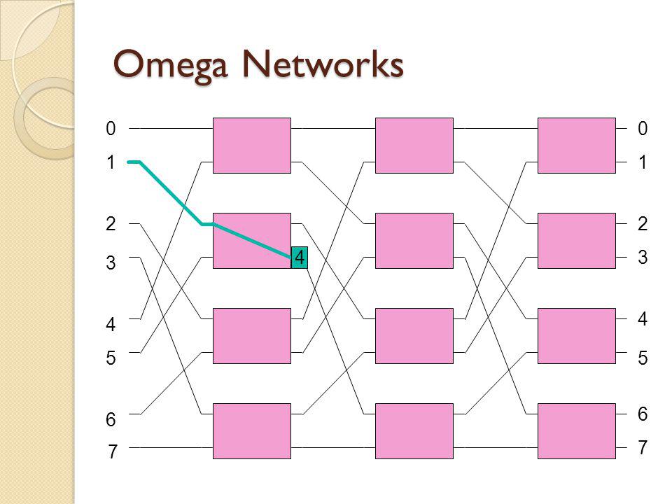
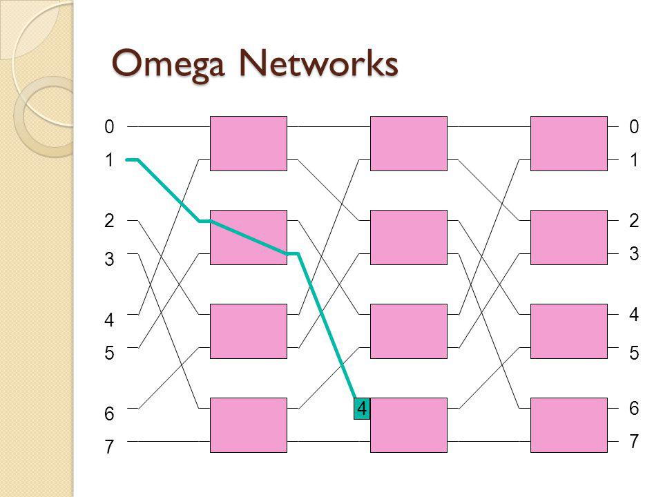
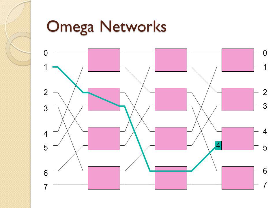
Omega Networks The omega network is another example of a banyan multistage interconnection network that can be used as a switch fabric The omega uses the perfect shuffle

27
Omega Networks 1 2 3 4 6 7 5 00 1 2 3 4 5 6 7 4

28
1 2 3 4 6 7 5 00 1 2 3 4 5 6 7 4

29
1 2 3 4 6 7 5 00 1 2 3 4 5 6 7 4
30
1 2 3 4 6 7 5 00 1 2 3 4 5 6 7 4
31
1 2 3 4 6 7 5 00 1 2 3 4 5 6 7 4

32
1 2 3 4 6 7 5 00 1 2 3 4 5 6 7 4
33
1 2 3 4 6 7 5 00 1 2 3 4 5 6 7 4

34
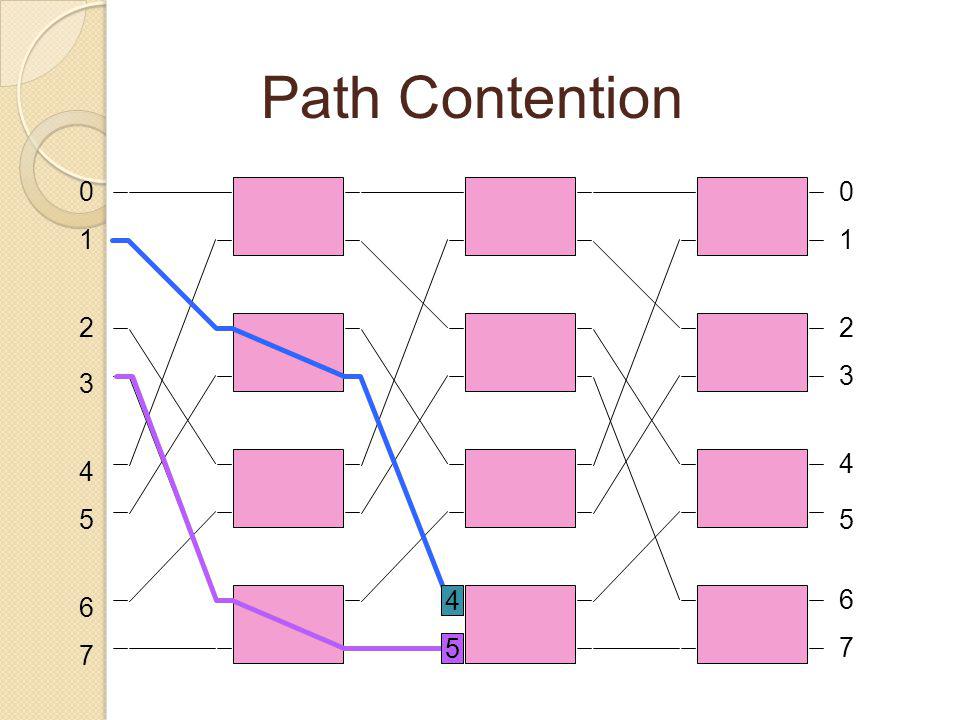
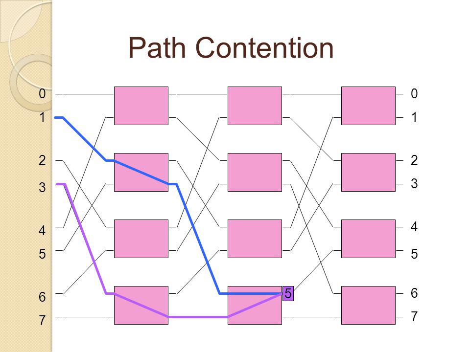
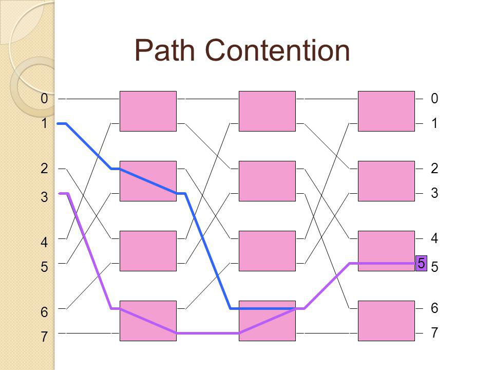
Path Contetion The omega network has the problems as the delta network with output port contention and path contention Again, the result in a bufferless switch fabric is cell loss (one cell wins, one loses) Path contention and output port contention can seriously degrade the achievable throughput of the switch
 Path contention and output port contention can seriously degrade the achievable throughput of the switch")
35
1 2 3 4 6 7 5 00 1 2 3 4 5 6 7 4 Path Contention 5

36
1 2 3 4 6 7 5 00 1 2 3 4 5 6 7 4 5

37
1 2 3 4 6 7 5 00 1 2 3 4 5 6 7 4 5

38
1 2 3 4 6 7 5 00 1 2 3 4 5 6 7 4 5
39
1 2 3 4 6 7 5 00 1 2 3 4 5 6 7

40
1 2 3 4 6 7 5 00 1 2 3 4 5 6 7 5
41
1 2 3 4 6 7 5 00 1 2 3 4 5 6 7 5

42
1 2 3 4 6 7 5 00 1 2 3 4 5 6 7 5
43
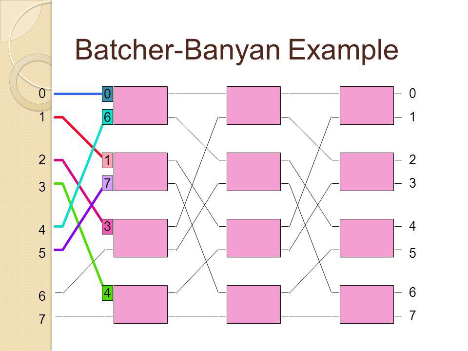
Batcher Sorter & Banyan Network One solution to the contention problem is to sort the cells into increasing order based on desired destination port Banyan networks are a class of MINs with the property that there is a unique path between any pair of source and destination

44
Batcher-Banyan Example 1 2 3 4 6 7 5 00 1 2 3 4 5 6 7 1 0 4 6 7 3

45
1 2 3 4 6 7 5 00 1 2 3 4 5 6 7 0 6 1 7 3 4
46
1 2 3 4 6 7 5 00 1 2 3 4 5 6 7 0 6 1 7 3 4

47
1 2 3 4 6 7 5 00 1 2 3 4 5 6 7 0 3 6 1 7 4

48
1 2 3 4 6 7 5 00 1 2 3 4 5 6 7 7 0 3 1 6 4

49
1 2 3 4 6 7 5 00 1 2 3 4 5 6 7 6 7 4 3 1 0

50
1 2 3 4 6 7 5 00 1 2 3 4 5 6 7 0 1 3 4 6 7

51
Clos Networks Clos networks have three stages: the ingress stage, middle stage, and the egress stage. Each stage is made up of a number of crossbar switches

52
BenesNetworks Clos networks may also be generalised to any odd number of stages. By replacing each centre stage crossbar switch with a 3-stage Clos network, Clos networks of five stages may be constructed. By applying the same process repeatedly,

53
Hybrid Networks Multiple-backplane Hierarchical buses Cluster tightly coupled computational units with high communication bandwidth Provide lower bandwidth intercluster communication link sctures performance comparable with homogeneous, high-bandwidth architectures energy efficiency is a strong driver toward using hybrid architectures.

54
Cluster Based 2-D Mesh At the lower level, each cluster consists of four processors connected by a bus. At the higher level, a 2-D mesh connects the clusters. The broadcast capability of the bus is used at the cluster level

55
Evaluation I # of linksNodaldegreeDiameterAvg. DistReliability 7 BinTree61.7142.211 8 Ring8242.212 9 Mesh122,66422 8 Cube12331,713

56
Evaluation I # of linksNodaldegreeReliabilityDiameterAvg. Dist 15 BinTree141.87163.5 16 Mesh243263 16 HyperCube324442.13 16 Chord.Ring324432

57
Power Consumption Under Different Number of Ports

58
Conclusion Shared Medium topologies have a bottleneck on shared medium. So not extensible Direct topologies can be easily extensible but there are thresholds between cost, performance and reliability Embed multiple logical dimension in one physical dimension using long wires is another disadvantage

59
Conclusion Indirect topologies blocking topologies have contention problems. Non blocking networks have extra stages and costs. Non-Blocking networks are cheaper than a crossbar with the same size Hybrid networks have high bandwith and energy efficiency using clustering

60
Conclusion Interconnect contention (internal blocking) induces significant power consumption on internal buffers, and the power consumption on buffers will increase sharply as throughput increases.
 induces significant power consumption on internal buffers, and the power consumption on buffers will increase sharply as throughput increases.")
61
References [1]N. Magen, A. Kolodny, U. Weiser, and N. Shamir. Interconnect-power dissipation in a microprocessor. In SLIP04, Feb. 2004. [2]Cidon, I., Keidar, I.: Zooming in on Network on Chip Architectures. Technion Department of Electrical Engineering, 2005 [3]Jose Duato, Sudhakar Yalamanchili, Lionel Ni, Interconnection Networks: An Engineering Approach, IEEE Computer Society Press, Los Alamitos, CA, 1997 [4]T.T. Ye: On-Chip Multiprocessor Communication Network Design and Analysis. Standford University of Electrical Engineering, Dec. 2003 [5] L Benini and G.D. Micheli, Networks on chips: a new SoC paradigm. IEEE Computer 35 1 (2002), pp. 70–78
![References [1]N. Magen, A. Kolodny, U. Weiser, and N.](http://images.slideplayer.com/5/1509301/slides/slide_61.jpg "Shamir. Interconnect-power dissipation in a microprocessor. In SLIP04, Feb [2]Cidon, I., Keidar, I.: Zooming in on Network on Chip Architectures. Technion Department of Electrical Engineering, 2005 [3]Jose Duato, Sudhakar Yalamanchili, Lionel Ni, Interconnection Networks: An Engineering Approach, IEEE Computer Society Press, Los Alamitos, CA, 1997 [4]T.T. Ye: On-Chip Multiprocessor Communication Network Design and Analysis. Standford University of Electrical Engineering, Dec [5] L Benini and G.D. Micheli, Networks on chips: a new SoC paradigm. IEEE Computer 35 1 (2002), pp. 70–78.")
62
Questions ??? Thanks

Similar presentations


>")
>")

 Interconnection Networks (notes by Ken Ryu of Arizona State) l Measure –How quickly it can deliver how much of what’s needed to.>")


>")

 Review session,>")


