Download presentation
Presentation is loading. Please wait.

2
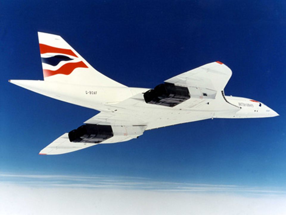
AEROSPACE PROPULSION AEROSPACE 410 ENGINE INTAKE AND NOZZLE SYSTEM
FOR A SUPERSONIC TRANSPORT PLANE CONCORDE SUBSONIC-SONIC-SUPERSONIC OPERATION Dr. Cengiz Camci

4
The Rolls-Royce/Snecma Olympus engines that are
fitted to Concorde are a highly developed version of the Bristol-Siddeley Olympus that was fitted to the Vulcan bomber, which generated 11,000Lbs of thrust.

8
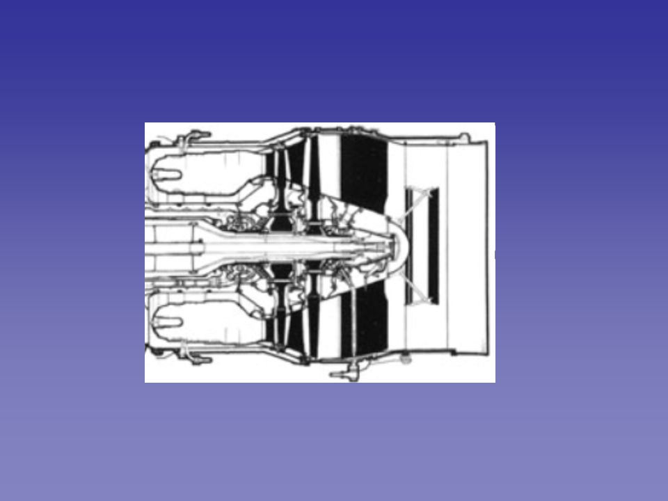
The Olympus engines are 2 spool engines. The inner shaft
revolves within the outer shaft. The engine consists of 14 compressor stages, 7 on each shaft, driven by their respective turbine systems. At supersonic speeds when the air approaches the combustion chamber is is very hot due to the high level of compression of 80:1.

9
The darker (black areas) are the areas more susceptible
to heat and are thus constructed out of the nickel-alloy. To protect the later compression stages the last 4 stages are constructed of a nickel-bassed alloy, the nickel alloy is usually reserved only for the turbine area.

10
Concorde is the only civil airliner in service
with a 'military style' afterburner system installed to produce more power at key stages of the flight. The reheat system, as it is officially known, injects fuel into the exhaust, and provides 6,000Lb of the total available thrust per engine at take off.

14
This hotter faster exhaust that is used on take off and is what
is mainly responsible for the additional noise that Concorde makes. The reheats are turned off shortly after take off when Concorde reaches the noise abatement area.

15
SUPERSONIC TRANSPORT CONCORDE
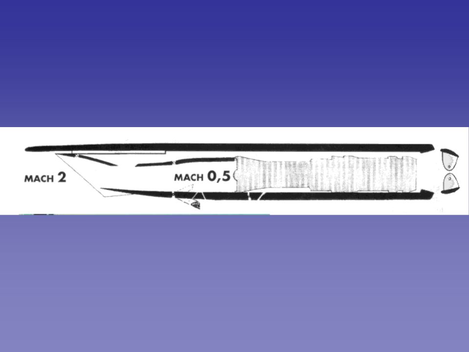
MACH INLET FOR THE SUPERSONIC TRANSPORT CONCORDE

17
ramps spill doors delta vortex forming at low speed
high angle of attack CCW ramps spill doors

18
AIR FLOW and INTAKES To further improve engine system performance, the air flow through the engine area is changed at different speeds via a variable geometry intake control system. Altering this airflow changes the amount of air available to the engine and the amount of air that in itself is producing thrust via the complex ramp and nozzle assemblies.

19
ramps ramps spill doors

20
The air intake ramp assemblies main job is
to slow down the air being received at the engine face to subsonic speeds before it then enters the engines. At supersonic speeds the engine would be unstable if the air being feed to it was also at a supersonic speed so it is slowed down before it gets there.

21
Subsonic Speeds (take off/subsonic cruise)
At take-off the engines need maximum airflow, therefore the ramps are fully retracted and the auxiliary inlet vane is wide open. The auxiliary inlet begins to close as the Mach number builds and it completely closed by the time the aircraft reaches Mach 0.93.

22
At slow speeds all the air into the engine is primary airflow
SUBSONIC CRUISE Secondary Exhaust buckets At slow speeds all the air into the engine is primary airflow and the secondary air doors are kept closed. Keeping them closed also prevents the engine ingesting any of its own exhaust gas. At around Mach 0.55 the secondary exhaust buckets begin to open as a function of Mach number to be fully open when The aircraft is at M=1.1

23
Shortly after take off the aircraft enters the noise
Abatement procedure where the re-heats are turned off and the power is reduced.

24
The secondary nozzles are opened further to allow
more air to enter, therefore quietening down the exhaust. The secondary air doors also open at this stage to allow air to by pass the engine. The ramps begin move into position at Mach 1.3 which shock wave start to form on the intakes.

25
SUPERSONIC SPEEDS At the supersonic cruse speed of Mach 2.0 the ramps have moved over half their amount of available travel, slowing down the air by producing a supersonic shockwave (yellow lines) at the engine intake lip.
 at the engine intake lip.")
26
SUPERSONIC CRUISE Some of the inlet fluid from the shock-boundary layer interaction zone is removed in the ramp area

27
Back to low speeds When the throttles are brought back to start the decent the spill door is opened to dump out excess air that is no longer needed by the engine, this allows the ramp to go down to their maximum level of travel. As the speed is lowered the spill doors are closed and the ramps begin to move back so by M=1.3 are again fully retracted.

28
ENGINE FAILURE Should an engine fail and need to be shut down during supersonic cruise, the ramps move fully down and the spill door opens to dump out excess air that is no longer required by the failed engine. The procedure lessens the chances of surges on the engine.

29
ENGINE FAILURE

30
THRUST REVERSAL After touch down the engines move to reverse power mode. The main effect of this is that the secondary nozzle buckets move to the closed position directing airflow forwards to slow the aircraft down.

31
SUBSONIC FLIGHT

32
ENGINE 4 ENGINE ROTATING STALL PROBLEM
The main issue is that at slow airspeeds the engine suffers vibrations on the low pressure compressor blades from air vortices, that are created by the wing leading edge sections, entering it from both the air intake and fully open Spill door that moving in an anti-clockwise direction, which is the opposite direction to the engine's direction of rotation. The effect is not seen on engine No1, as the vortices travel in the same direction as the aircraft. The No4 engine is limited on take off to 88% N1 at speeds below 60 Knots.

33
Engine rotational direction is clockwise
VORTICAL STRUCTURES OF FLOW at engine inlet IS IN COUNTER CLOCKWISE DIRECTION 1 4 If you stand underneath or behind Concorde during take off it can be clearly seen that the no4 spill door is not as open as the other three. The reheat flame on engine 4 is also not as bright or stable as the other three during the initial take off roll, until the aircraft is around 60 knts when it matches the others.

Similar presentations