Download presentation
Presentation is loading. Please wait.

1
Wireless Distribution and Supply Chain Services
Atlanta | Chicago |Dallas | Newark | Los Angeles | Seattle Calgary | Montreal | Toronto Outdoor In-Building Supply Chain

2
Dean’s List Discount Campaign lasts until October 14
Eligibility Rules: Someone from the customer’s company must be in attendance for five of the Hutton HOW U webinars that take place prior to October 14. The same person does not have to attend all five webinars. Customer must have spent $7,500 at Hutton during this calendar year prior to October 14 All customers meeting the above criteria on October 14 will be entered into a drawing. The first customer drawn will win a $1,000 gift certificate to Hutton Communications The next four customers drawn will all win $500 gift certificates to Hutton Communications For every webinar attended beyond the required five, your company will earn an extra entry into the drawing, assuming your company meets the $7,500 spend criteria.

3
Hutton Offers the Largest Selection of PIM Jumpers Anywhere
HOW U Upcoming webinars: In-Building Installation Planning: Going from Assumptions to facts: 6/29/11 Solutions for Transporting TDM Traffic Over Packet Switched Networks: 6/30/11 Control PIM with a Proactive, System-Wide Approach: 7/14/11 Hutton Offers the Largest Selection of PIM Jumpers Anywhere - Looking for Andrew factory PIM rated jumpers? Hutton has them. In stock. Ready to ship. - Premium, custom length PIM tested jumpers? Hutton is your best option. - Right angle connectors? No one has more choices than Hutton

4
Microwave PTP 101 What we’ll cover Radio types and functions
Dish sizes and configurations Frequency planning and network types Design steps for a successful deployment

5
Choosing the right radio style
All Outdoor Radio – radio unit will have an integrated antenna, or connectors. Typically mounted close to antenna or dish and fed by fiber or Ethernet cable and PoE powered. Easy to install, typically lowers overall installation cost. Most radios are IP based and have limited TDM capabilities. Split Mount Radio – Two main components, indoor unit (IDU) and an outdoor unit (ODU). Two components are connected by using 3/8” coax cable. IDU is typically rack mounts and the ODU can either connect directly to the dish or be remote mounted and connected to dish using coax or flextwist jumpers. IP and TDM capabilities increase, higher installation cost overall compared to the all outdoor solution. All Indoor Radio – All radio components on the ground. Large coax or elliptical waveguide is ran to dish. Most expensive solution to install. However, in the event of a radio outage, no tower climbing is involved. Most public safety networks are all indoor based.
 and an outdoor unit (ODU). Two components are connected by using 3/8 coax cable. IDU is typically rack mounts and the ODU can either connect directly to the dish or be remote mounted and connected to dish using coax or flextwist jumpers. IP and TDM capabilities increase, higher installation cost overall compared to the all outdoor solution. All Indoor Radio – All radio components on the ground. Large coax or elliptical waveguide is ran to dish. Most expensive solution to install. However, in the event of a radio outage, no tower climbing is involved. Most public safety networks are all indoor based.")
6
Half Duplex/Full Duplex
Half-Duplex provides communication in both directions, but only one direction at a time. Most unlicensed radios are half-duplex. So if the radio is listed at 200Mbps, 100Mbps is TX, 100Mbps is RX. Full-duplex allows communication in both directions simultaneously. Licensed radios are full-duplex.

7
Time Division Multiplexing
TDM is a method of putting multiple data streams in a single signal by separating the signal into many segments, each having a very short duration. Example of TDM is T1 or T3 service. When TDM ports are used on a microwave radio, bandwidth will be subtracted from the IP bandwidth of the radio. DS0 – 64Kbps (typical voice circuit, 24 DS0’s equal a T1 circuit) T1 (DS1) = Mbps (28 T1’s equal a T3) T3 (DS3) = 45 Mbps (3 T3’s equal an OC3) OC3 (STS3) = Mbps (4 OC3’s equal an OC12) OC12 = Mbps TDM traffic does not tolerate a high noise floor, understand your RF environment before deploying.
 T1 (DS1) = Mbps (28 T1’s equal a T3) T3 (DS3) = 45 Mbps (3 T3’s equal an OC3) OC3 (STS3) = Mbps (4 OC3’s equal an OC12) OC12 = Mbps. TDM traffic does not tolerate a high noise floor, understand your RF environment before deploying.")
8
Ethernet/IP Ethernet is the most popular and considered the network topology standard for most computer and VoiP connections. Connections are made at 10/100Mbps or 1/10Gbps. Cable lengths limited to 325ft between active devices. IP is a network layer protocol for addressing and routing packets of data between host on a TCP/IP network. IP is a connectionless protocol that provides best effort delivery. Most important part when designing an Ethernet backhaul is understanding the customers bandwidth needs. What is type of data is being sent across the network? How many concurrent users? What is the plan for future growth?

9
OFDM? Orthogonal Frequency Division Multiplexing
Found in Unlicensed Radios Only Distributes the data over a large number of carriers that are spaced apart at precise frequencies. Works well in non-LOS and harsh RF environments.

10
BridgeWave: Who We Are Specializing in high capacity wireless solutions for 4G backhaul Microwave and Millimeter Wave Solutions Market leader in GigE wireless millimeter wave solutions 67% of all US registrations 78% of all UK registrations Over 11,000 gigabit radios sold and deployed in over 50 countries GigE wireless links yield significant ROI compared to leased fiber Solutions For: Mobile Operators Service Providers Government/Municipalities Education Healthcare Private Networks/Enterprise Corporate Headquarters: Santa Clara, CA

11
BridgeWave Products at-a-Glance
Data Rates Features Distance 60 GHz FE60, GE60, AR60, AR60X 100 Mbps, 1000 Mbps AdaptRate AdaptPath 256-AES 2 port switch Up to 1 mile 80 GHz FE80U, GE80, AR80, BW80 FE80XU, GE80X, AR80X, BW80X 250 Mbps, 500 Mbps, Up to 5 miles FlexPort80 FP80-12-E, FP T, FP T 240 Mbps, 600 Mbps, 1200 Mbps ARM, 256-AES, TDM+IP, RF Tuning, QPSK, QoS, OAM, 5 port switch FlexPort 2400 Mbps ARM, 256-AES, RF Tuning, QoS, 5 port switch Up to 3 miles FlexPort µWave FP18, FP23, FP24 330 Mbps, 660 Mbps, ARM, 256-AES, Single ODU for 1 Gbps, QoS 5 port switch Up to 10 miles

12
Alvarion – Company Overview
4G Broadband Wireless Leader 300+ Commercial 4G networks deployed; more than 300M people covered Focused on innovation in broadband wireless Customized solutions targeted at market segments Utilities & Smart Grid – gas/water/electric Municipal networks – public broadband/transportation/education Public Safety – surveillance and emergency response Enterprise networks Future-proof solution to meet fixed, mobile and nomadic deployment needs Access & backhaul solutions Licensed and license-exempt frequencies BreezeNET B Wi2 BreezeACCESS VL 900Mhz SU-Video E1/T1 BreezeMAX Extreme Private Network Solution Private Network Solutions

13
Alvarion’s P2P Product Family - BreezeNET B
13 Product Frequency BW Max Throughput Solution Highlights BreezeNET B10 5.X GHz 10/20 MHz 10 Mbps Link in a box Attractive pricing 5 Mbps uplink and 5 Mbps downlink BreezeNET B14 5.X GHz and 2.4 GHz 10/20/40 MHz 14 Mbps QoS (WLP) Scalable to B28 and B100 Supports 1 optional E1\T1 link 7 Mbps uplink and 7 Mbps downlink BreezeNET B28 28 Mbps Scalable to B100 Supports 2 optional E1\T1 links 21 Mbps uplink and 21 Mbps downlink BreezeNET B100 100 Mbps High-end, high-capacity robust solution Supports up to 4 optional E1\T1 links 70 Mbps uplink and 70 Mbps downlink BreezeNET B300 GHz 5/10/20/40 MHz 250 Mbps High-end, high-capacity, robust solution 250 Mbps aggregated throughput One platform for an extensive frequency range Supports up to 4 E1/T1 links
 Scalable to B28 and B100. Supports 1 optional E1\T1 link. 7 Mbps uplink and 7 Mbps downlink. BreezeNET B Mbps. Scalable to B100. Supports 2 optional E1\T1 links. 21 Mbps uplink and 21 Mbps downlink. BreezeNET B Mbps. High-end, high-capacity robust solution. Supports up to 4 optional E1\T1 links. 70 Mbps uplink and 70 Mbps downlink. BreezeNET B GHz. 5/10/20/40. MHz. 250 Mbps. High-end, high-capacity, robust solution. 250 Mbps aggregated throughput. One platform for an extensive frequency range. Supports up to 4 E1/T1 links.")
14
Dish and Radio Channel Size
Unlicensed Spectrum – Yagi, Panels, Sectors, Dishes 23GHz – 1ft Dish / 50MHz Channel 18GHz – 2ft Dish / 80MHz Channel 11GHz – 2ft Class B, 3ft Class A Dish / 40MHz Channel 6GHz – 6ft Dish / 30MHz Channel The Equation for a successful radio reception: TX power + TX antenna gain – Path loss – Cabling loss + RX antenna gain – 10dB fade margin > RX Radio sensitivity or (less commonly) RF noise floor
 RF noise floor.")
15
Radio Waves - Quality Products Matter
Leader in innovation Ease of deployment Great pattern performance Single and Dual Polarity Dishes 2GHz to 60GHz Antennas and Dishes High Quality

16
Space Diversity Used to overcome reflection of microwave paths over long distances. Requires transmit antenna and two receiver antenna The two receive dishes enables the reception of signals via different propagation paths. It requires double antenna on each side of the hop.

17
Reflection For Ground & Water Reflections Tx S/D Rx
Space Diversity antennas located to de-correlate ground or water reflections. Ra Rb Height-Gain Pattern S = Optimal Spacing 2S = Aesthetic only S k = 4/3 Water Reflections 2S Tx S/D Rx R’a R’ b

18
Antenna Polarization Point-to-Point (backhaul) systems may use either vertical or horizontal polarization as long the same polarization is used at each end. Horizontal polarization may perform slightly better when transmitting through a forested area, otherwise there is very little difference in propagation effects.
 systems may use either vertical or horizontal polarization as long the same polarization is used at each end. Horizontal polarization may perform slightly better when transmitting through a forested area, otherwise there is very little difference in propagation effects.")
19
How Far Will It Go? 6 GHz (10-40+ miles) 11 GHz (5-20 miles)
 11 GHz (5-20 miles)")
20
Frequency Planning The objective of frequency planning is to assign frequencies to a network using as few frequencies as possible and in a manner such that the quality and availability of the radio link path is minimally affected by interference. The following aspects are the basic considerations involved in the assignment of radio frequencies

21
Chain Configuration w/ Frequency Planning
All sites reside on a single path. This is a very sensitive topology in which the first link malfunction can cause a complete network failure. f1 HP U f1 VP L f1 HP U

22
Star Configuration w/ Frequency Planning
Star Topologies use a separate link from a hub to each site. This is very simple, but inefficient for microwave systems, as it requires possible longer paths and LOS for each link. The star topology also makes for poor frequency reuse since all links originate at the same point. U U VP HP HP U L HP VP U U Micrwave Link Design Micrwave Link Design

23
Ring Configuration w/ Frequency Planning
The ring topology provides superior network availability, due to the rings inherent path diversity. In a ring topology, service failures occur when two or more links malfunction. U U L HP VP VP HP L VP U L VP

24
What is 99.999 Reliability? What type of network are you backhauling?
How much downtime can your network tolerate? Availability % Downtime per year Downtime per month* Downtime per week 90% ("one nine") 36.5 days 72 hours 16.8 hours 95% 18.25 days 36 hours 8.4 hours 98% 7.30 days 14.4 hours 3.36 hours 99% ("two nines") 3.65 days 7.20 hours 1.68 hours 99.5% 1.83 days 3.60 hours 50.4 minutes 99.8% 17.52 hours 86.23 minutes 20.16 minutes 99.9% ("three nines") 8.76 hours 43.2 minutes 10.1 minutes 99.95% 4.38 hours 21.56 minutes 5.04 minutes 99.99% ("four nines") 52.56 minutes 4.32 minutes 1.01 minutes 99.999% ("five nines") 5.26 minutes 25.9 seconds 6.05 seconds % ("six nines") 31.5 seconds 2.59 seconds 0.605 seconds
 36.5 days. 72 hours hours. 95% days. 36 hours. 8.4 hours. 98% 7.30 days hours hours. 99% ( two nines ) 3.65 days hours hours. 99.5% 1.83 days hours minutes. 99.8% hours minutes minutes. 99.9% ( three nines ) 8.76 hours minutes minutes % 4.38 hours minutes minutes % ( four nines ) minutes minutes minutes % ( five nines ) 5.26 minutes seconds seconds % ( six nines ) 31.5 seconds seconds seconds.")
25
Understanding the Basics
Free Space Loss (FSL) – is the expected attenuation of a signal as it travels away from a transmitting device. As the path distance increase, the power density decreases. Fade Margin – the difference between the unfaded receive signal level and the receiver sensitivity threshold. Every link must have sufficient Fade Margin to protect against path fading that weakens the radio signal. Link Availability – Fade margin is directly related to link availability, which is the percentage of time that the link is functional. The percentage of time that the link is available increases as the fade margin increases. Bottom line, design your link as far away from the radio’s receiver threshold as possible. Path Fading – path fading occurs more frequently in flat, humid environments than in rough, dry locations. Therefore, a link in a flat humid area requires a greater fade margin to achieve the same level of link availability as a link in a rocky and dry location.
 – is the expected attenuation of a signal as it travels away from a transmitting device. As the path distance increase, the power density decreases. Fade Margin – the difference between the unfaded receive signal level and the receiver sensitivity threshold. Every link must have sufficient Fade Margin to protect against path fading that weakens the radio signal. Link Availability – Fade margin is directly related to link availability, which is the percentage of time that the link is functional. The percentage of time that the link is available increases as the fade margin increases. Bottom line, design your link as far away from the radio’s receiver threshold as possible. Path Fading – path fading occurs more frequently in flat, humid environments than in rough, dry locations. Therefore, a link in a flat humid area requires a greater fade margin to achieve the same level of link availability as a link in a rocky and dry location.")
26
Understanding Your Rain Region
Rain Region Map: The energy of microwave signals is absorbed by rain: rain can cause an outage if enough energy is absorbed so that the receiver loses the signal

27
Rain Region Maps Crane ITU-R

28
Propagation Regions

29
Climate Conditions and Path Fading
Climate Factor Climate Conditions and Path Fading Path fading occurs more frequently in flat, humid environments than in rough, dry locations. Therefore, a link in flat and humid areas requires a greater Fade Margin to achieve the same level of link availability as a link in a rocky and dry location. When calculating link performance the climate factor must be taken in consideration

30
Line-of-Sight LOS (clear Fresnel Zone)
Near LOS (60% of Fresnel Zone clear) Non-LOS (majority of Fresnel Zone blocked)
 Non-LOS (majority of Fresnel Zone blocked)")
31
Propagation Loses Obstacle Loss –also called Diffraction Loss or Diffraction Attenuation. One method of calculation is based on knife edge approximation. Having an obstacle free 60% of the Fresnel zone gives 0 dB loss 20dB 16dB 6dB 0dB 0dB

32
Map Info of Tree Heights
A database of tree heights was assembled based on 10 years of field survey data. MapInfo was used to plot this map.

33
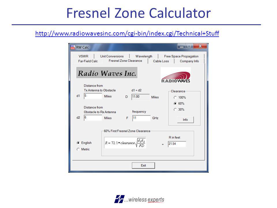
Fresnel Zone Calculator
34
Importance of a Site Survey
What is your customers budget? What throughput does customer need? Do you have line-of-sight for your path? How are you mounting radios or dishes? What is your cable path from radio to network head end? Look for good grounding sources. Don’t forget lightning protection.

35
Importance of Spectrum Analysis
Spectrum analysis is a must for unlicensed spectrum (900MHz, 2.4, 5.3, 5.4, 5.8GHz). Spectrum analysis should be considered for 4.9GHz and 3.65GHz spectrum. Spectrum analysis should be performed at height of antennas and dishes. Document the noise floor and look for open channels. Never assume that just because it’s rural that there is no noise floor, if towers are in the area, there is noise. Consider making an investment or renting a good spectrum analyzer
. Spectrum analysis should be considered for 4.9GHz and 3.65GHz spectrum. Spectrum analysis should be performed at height of antennas and dishes. Document the noise floor and look for open channels. Never assume that just because it’s rural that there is no noise floor, if towers are in the area, there is noise. Consider making an investment or renting a good spectrum analyzer.")
36
Rules to Remember As frequency rises, available bandwidth typically rises, but distance and ability to overcome obstacles is reduced. The more sensitive the radio, the lower the power signal it can successfully receive, stretching right down to the noise floor. As radio modulation increases, receiver sensitivity decreases. Know your noise floor, do a spectrum scan, survey your area to see what else is hanging in the air. Establish a fade margin of no less than 10dB in good weather conditions, this will provide a high degree of assurance that the system will continue to perform effectively in a variety of weather or interference. Avoid obstructions in your path whenever possible and understand the distance between you link. Avoid force fitting a solution, hoping it will work. Never go “cheap” on your cable Understand your application and choose accordingly

37
Sales Engineer POC Bob Hagarman Mark Billets Phone: 717-524-7922
Mark Billets Phone:

38
Thank You!

39
Comprehensive Alvarion Portfolio for Diverse Needs
Mobile, fixed and nomadic wireless 4G Solution Licensed and license-exempt frequencies Point to Point & Point to Multipoint offering BreezeMAX® Extreme BreezeMAX® Macro Indoor BreezeMAX® Macro Outdoor BreezeMAX® WI2 BreezeACCESS VL

40
Extreme 4G Solution: 3.65GHz, 4.9GHz -5.9GHz
MIMO Single Sector 2x2 BreezeMAX Extreme Superior performance utilizing 2nd order diversity Maximal sector coverage (MIMO A) & Capacity (MIMO-B) Up to 5, 10, MHz per sector Integrated Antenna & ASN GW Built in Mobility Support Cost efficient solution with zero footprint – Low CAPEX Maximizing Coverage with 2nd order Diversity 6-7Miles for 90% coverage Fast ROI with High capacity MIMO B: 40 Mbps (10 MHz), 80 Mbps (20 MHz)
 & Capacity (MIMO-B) Up to 5, 10, MHz per sector. Integrated Antenna & ASN GW. Built in Mobility Support. Cost efficient solution with zero footprint – Low CAPEX. Maximizing Coverage with 2nd order Diversity. 6-7Miles for 90% coverage. Fast ROI with High capacity. MIMO B: 40 Mbps (10 MHz), 80 Mbps (20 MHz)")
Similar presentations


 High-Speed LANs. 2 Introduction Fast Ethernet and Gigabit Ethernet Fast Ethernet and Gigabit Ethernet Fibre Channel Fibre Channel High-speed.>")


>")


>")
