Download presentation
Presentation is loading. Please wait.

1
HEATING COOLING VENTILATION
HVAC HEATING COOLING VENTILATION

2
Human Comfort Zone As humans we try to maintain a body
temperature of 98.6° F Three Mechanisms Heat generated within the body Heat gained from surroundings Heat lost to surroundings

3
Human Comfort Zone We shiver to generate heat

4
Human Comfort Zone We sweat to Give off heat

5
Human Comfort Zone We get goose bumps

6
Human Comfort Zone Blood Flow Decreases to hands and feet in winter
Increase in summer to encourage heat loss

7
Thermal Neutrality To be comfortable humans must loose heat at the same rate as it is produced or gained.

8
Factors Affecting Human Comfort
Air temperature Air Speed Humidity Mean radiant temperature Each has a direct influence on heat loss or gain to the human body

9
Factors Affecting Human Comfort
Air Temperature - This affects temperature differences between the body and the surroundings, consequently affecting the rate of heat loss or gain by convection.

10
Factors Affecting Human Comfort
Air Speed - This affects the rate at which the body loses heat by convection. An air temperature of 35°F and a wind speed of 20 miles/hour combine to give a wind chill temperature of 11.2°F. Air speed is also very important during summer when the body is trying to lose heat to maintain comfort.

11
Factors Affecting Human Comfort
Humidity - Affects the rate at which the body loses heat by evaporation. During hot weather, high humidity increases discomfort by making it more difficult to evaporate perspiration into the air.

12
Mean Radiant Temperature
Mean Radiant Temperature' (MRT). This is defined as the temperature of a sphere at the point in question which would exchange no net radiation with the environment.
. This is defined as the temperature of a sphere at the point in question which would exchange no net radiation with the environment.")
13
Factors Affecting Human Comfort
Mean Radiant Temperature (MRT) - MRT is the average surface temperature of the surroundings with which the body can exchange heat by radiant transfer. Radiant heat transfer to and from the body is quite apparent when sitting near a fireplace (high MRT) or large cold window area (low MRT).
 - MRT is the average surface temperature of the surroundings with which the body can exchange heat by radiant transfer. Radiant heat transfer to and from the body is quite apparent when sitting near a fireplace (high MRT) or large cold window area (low MRT).")
14
Mean Radiant Temperature
In general for every 1 degree F that the MRT drops, the air temperature must be raised about 1.4 degrees F to achieve comfort conditions. How can you raise the MRT? Close blinds and curtains Solar Film on windows Seal heat leaks

15
Comfort Comfort is achieved by either increasing the ambient temperature or by raising the mean radiant temperature of an environment. A higher radiant temperature means that people become comfortable with a lower ambient temperature and the reverse is also true.

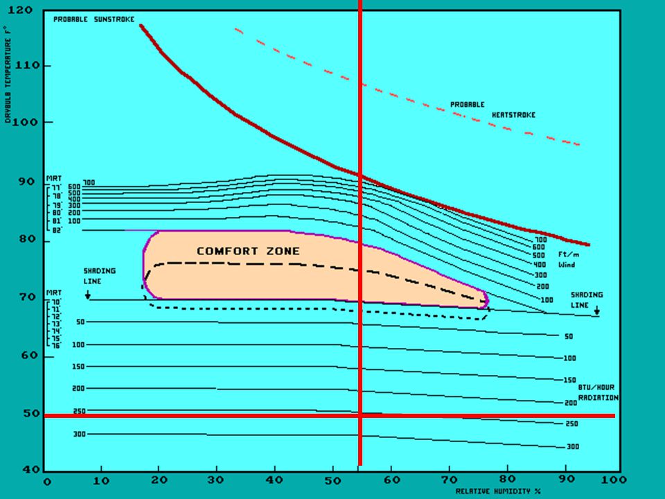
16
Bioclimate Chart Dotted area shows the comfort zone during the winter.

17
Example 1 Dry Bulb 73° Relative Humidity 50%

18
In the zone

19
Example 2 Dry Bulb Temp. 78° Relative Humidity 70%

21
Example 2 Dry Bulb Temp. 78° Relative Humidity 70%
Requires a wind speed of 250 FPM (250*60)/5280 MPH = 2.84
/5280. MPH =")
22
Example 3 Dry Bulb Temp. = 50°F Relative Humidity 55%

24
Example 3 Dry Bulb Temp. = 50°F Relative Humidity 55% BTU/Hour = 250

26
Definitions Conduction
A method by which heat is transferred from a warmer substance to a cooler substance by molecular collisions. Direct contact. Convection A method by which heat is transferred by currents in a liquid or gas. Radiation A method by which heat can be transferred through objects and empty space. Electromagnetic.

27
Conduction Examples Liquid - Liquid - Pouring cold cream into coffee
Liquid - Gas - Ocean and Atmosphere Gas - Gas – Cold and warm weather systems mixing Solid - Solid – Touch a hot pot on a stove

28
Conduction Rate Factors
Contact Area Type of Material Cast Iron vs Stainless Steel Temperature Difference Distance heat must travel

29
Convection Examples In a closed room cool air will settle to the bottom while warm air will rise Bowl of soup – Hot liquid in the center moves to the cooler outside where it drops and is reheated at the center and the cycle continues. Warm air rising through a heat register

30
Radiation Examples The sun’s heat A bonfire Warm soil on a cool night

31
Radiation Rate Factors
Surface area Type of material Temperature difference

32
More Radiation Terms Reflectance (or reflectivity) refers to the fraction of incoming radiant energy that is reflected from the surface. Reflectivity and emissivity are related and a low emittance is indicative of a highly reflective surface. For example, aluminum with an emittance of 0.03 has a reflectance of 0.97.
 refers to the fraction of incoming radiant energy that is reflected from the surface. Reflectivity and emissivity are related and a low emittance is indicative of a highly reflective surface. For example, aluminum with an emittance of 0.03 has a reflectance of")
33
More Radiation Terms Emittance (or emissivity), refers to the ability of a material’s surface to give off radiant energy. All materials have emissivities ranging from zero to one. The lower the emittance of a material, the lower the heat radiated from its surface.
, refers to the ability of a material’s surface to give off radiant energy. All materials have emissivities ranging from zero to one. The lower the emittance of a material, the lower the heat radiated from its surface.")
34
Emissivity or Emittance
Material Surface Emittance Asphalt Aluminum foil 0.03 – 0.05 Brick 0.93 Fiberglass 0.80 – 0.90+ Glass 0.95 Steel 0.12 Wood 0.90

35
R-Value R-Value is the measure of resistance to heat flow through the defined material. The higher the R-Value the less heat will transfer through the wall, making the system more energy efficient. U-Value –is the reciprocal of the R-Value (1/R) and is a measure of the rate of heat loss
 and is a measure of the rate of heat loss.")
36
WINDOWS - 4 Ways to Evaluate
U-FACTOR Solar Heat Gain Coefficient Visible Transmittance Air Leakage

37
U-FACTOR U-FACTOR The rate of heat loss is indicated in terms of the U-Factor of a window assembly. The insulating value is indicated by the R-Value which is the inverse of the U-Value. The lower the U-Value the greater a windows resistance to heat flow and the better the insulating value.

38
Solar Heat Gain COEFFICIENT
The SHGC is the fraction of incident solar radiation admitted through a window. SHGC is expressed as a number between 0 and 1. The lower a windows solar heat gain coefficient, the less solar heat it transmits.

39
VISIBLE TRANSMITTANCE
The visible transmittance is an optical property that indicates the amount of visible light transmitted. Theoretical values vary between 0 and 1, but most values are between 0.3 and 0.8

40
Air Leakage Heat loss and gain occur by infiltration through cracks in the window assembly. Air leakage is expressed in cubic feet of air passing through a square foot of window area. .3 is recommended for Oregon

41
Low-E Windows Glass is coated with silver or tin oxide which allows visible light to pass through but reflects infrared heat radiation back into the room. Reduces heat loss Allows visible light to pass through but reflects infrared heat radiation away from the room Reduces heat gain

42
High number for cold climate. Low number for warm climates
The lower the number the better the insulating value Visible Light Transmittance The percentage of visible light ( nm) that is transmitted through the glass. Varies from 0 to 1.0 The higher the # the more light is transmitted. The best windows have air leakage rating between 0.1 and 0.6 cfm/ft.
 that is transmitted through the glass. Varies from 0 to 1.0 The higher the # the more light is transmitted. The best windows have air leakage rating between 0.1 and 0.6 cfm/ft.")
43
Single-Glazed with Clear Glass

44
Single-Glazed with Bronze or Gray Tinted Glass

45
Double-Glazed with High-Solar-Gain Low-E Glass, Argon/Krypton Gas

46
Triple-Glazed** with Moderate-Solar-Gain Low-E Glass, Argon/Krypton Gas

47
Ventilation Multi Point Fan Systems One fan located in the attic
Connects to baths and kitchen Timed to run at high speed during high use times such as morning (showers, bacon ) and evening. Xvent
 and evening. Xvent.")
48
Heat Recovery Ventilation
How it works In the heating season the core transfers heat from the outgoing, stale household air to preheat the incoming, fresh air. Cross-current sections, ensure the two air streams are always kept separate preventing the incoming fresh air from being contaminated by the outgoing stale air.

49
Heat Recovery Ventilation
During the air-conditioning season, the HRV reverses this process, removing some of the heat from the incoming air and transferring it to the outgoing air.

50
Heat Recovery Ventilation

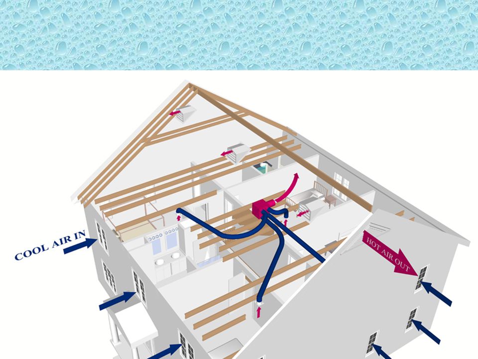
51
Ventilation Heat Recovery System - uses fans to maintain a low-velocity flow of fresh outdoor air into the building (incoming air stream) while exhausting out an equal amount of stale indoor air (exhaust air stream). Fresh air is supplied to all levels of the building while stale air is removed from areas with high levels of pollutants and moisture.
 while exhausting out an equal amount of stale indoor air (exhaust air stream). Fresh air is supplied to all levels of the building while stale air is removed from areas with high levels of pollutants and moisture.")
52
Ventilation Heat Recovery System
Air Exchange - Expels stale, polluted indoor air and gaseous pollutants and continually exchanges them with a continuous flow of fresh, revitalized outdoor air to improve Indoor Air Quality.

53
Ventilation Heat Recovery System
Excess Humidity Control - Helps prevent uncontrolled excess humidity by expelling excess humidity from the air, thereby reducing the risk of window condensation, mildew and mold, which prevents structural damage and deterioration to your home.

54
Ventilation Heat Recovery System
Heat Recovery Core - As warm air is expelled from your house, it warms the incoming cold, fresh air before it’s circulated throughout your home. The result is a constant supply of fresh air, no unpleasant drafts and greater home comfort.

55
HRV

56
HRV Sized to ventilate the entire house at a minimum of .35 air changes per hour. Minimum CFM requirement can be calculated as follows Determine square footage and multiply times ceiling height. Divide by 60 minutes Multiply times .35 (minimum air changes)
")
57
HRV Calculation Example
Determine square footage and multiply times ceiling height. Divide by 60 minutes Multiply times .35 (minimum air changes)
")
58
HRV Calculate the minimum CFM for a home
with 2000SF main level, 1000SF second level and 750 SF finished basement Note: Main and second level have 9 foot ceilings and basement has 8 foot ceiling.

59
Solution 3000 SF x 9’ = 27000 750 x 8’ = 6000 Total 33000
33000/60 = 550 .35 x 550 = CFM EBM – Energy By Motion

60
Particulate Air Filter
HEPA Filter High Efficiency Particulate Air Filter

61
Energy Recovery Ventilators

62
How are HRV’s Installed?

63
How are HRV’s Installed?

64
How are HRV’s Installed?

65
Radiant Floor Heat Three types Radiant Air Floors
Electric Radiant Floors Hot Water (Hydronic)
")
66
Radiant Floor Heat Types of installation Wet Installations
Large thermal mass of a concrete slab floor lightweight concrete over a wooden subfloor Dry Installations Where the installer "sandwiches" the radiant floor tubing between two layers of plywood or attaches the tubing under the finished floor or subfloor.

67
Radiant Floor Heat Air Heated Radiant Floors Not recommended for residential applications Electric Radiant Floors -

68
Electric Radiant Heat - Wet Installation

69
Wet Installation

70
Wet Installation

71
Dry Installation easily installed directly under tile or natural stone to provide comfortable floor temperatures in your bathroom, kitchen, entryway, or other hard surfaced areas. Compatible with all standard sub flooring materials, and its low 3/16" (3 mm) profile, also make it ideal for renovations.
 profile, also make it ideal for renovations.")
72
Dry Installation Retrofit

73
Hydronic Radiant Heat Low Mass Modular Board

74
Wet Installation PEX piping in Concrete (thick slab)
")
75
Wet Installation Thin Slab Application Gypcrete over plywd

76
Electric Toe Kick Heat

77
Toe Kick Electric Heat

78
Heat Pump and Furnace Indoor Cooling Coil Thermostat Furnace Heat Pump
Air Cleaner

79
Heat Pump and Air Handler
Thermostat Air Handler Heat Pump Air Cleaner

80
Air Conditioner and Furnace
Thermostat Indoor Cooling Coil Air Cleaner Air Conditioner Furnace

81
Air Conditioners and Air Handlers
Thermostat Air Handler Air Conditioner Air Cleaner

82
Cooling

Similar presentations


>")

 Structural Moisture Control Air Infiltration Thermal Insulation.>")


