Download presentation
Presentation is loading. Please wait.

1
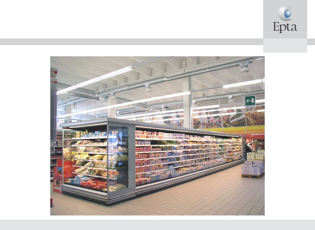
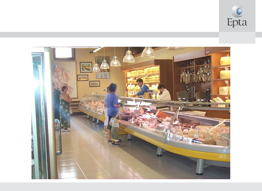
REFRIGERATION SYSTEMS
ALL - CO2 SUPERMARKET REFRIGERATION SYSTEMS

2
CO2 REFRIGERATING UNITS
Kyoto protocol and its consequences Why CO2 State of the art

3
KYOTO PROTOCOL AND EU Kyoto protocol
Came into force from February 16th 2005, Over 160 nations involved Greenhouse gas emission reduction Strong influence on refrigeration and air conditioning EU banishes HFCS, HCFCS, restricts the use of HFCS Many important nations, such as Australia, Canada and Japan, set funds for HFCS emission reduction Russia ratified Kyoto protocol on 2004 EU proposal: evolution of regulation 2037/2000 Obligation to perform regular leak test Reporting duties regarding greenhouse gas emission Logbooks for control and recharging operations Phase out R134a in automotive air conditioners from 2014 (probably replaced by CO2) Several North European countries are moving to natural refrigerants Danish government applies a 100€ for 1 kg of HFCS in taxes
 Several North European countries are moving to natural refrigerants. Danish government applies a 100€ for 1 kg of HFCS in taxes.")
4
ALTERNATIVES Natural refrigerants: Why CO2 Ammonia NH3
Know how available Toxic/Flammable Indirect system required Water condensation Hydrocarbons HC Know how available Flammable/Explosive Indirect system required Reliable for domestic refrigeration Largely available in nature (GWP=1) Very low cost respect to traditional refrigerants High refrigerating capacity Not toxic/Not flammable Direct expansion system with heat recovery Redesign components required EPTA CHOICE Carbon Dioxide CO2
 Very low cost respect to traditional refrigerants. High refrigerating capacity. Not toxic/Not flammable. Direct expansion system with heat recovery. Redesign components required. EPTA CHOICE. Carbon Dioxide CO2.")
5
OUR CONCLUSIONS Secondary systems aren’t economical choices, especially in LT. A DX concept is needed The only natural fluid that can be used without harm is CO2

6
PLANT SOLUTIONS Secondary fluid system Centralised CO2 system MT and LT pack with R404A or NH3 and CO2 as a secondary refrigerant subject to phase change Direct expansion CO2 LT in cascade with R404A or NH3 MT Direct expansion CO2 LT and MT with heat realised directly into the atmosphere

7
SECONDARY FLUID SYSTEM
HFC, NH3 or HC ADVANTAGES Low pressure in piping High evaporator efficiency DISADVANTAGES CO2 pump Two refrigerants are used Pump energy consumption Plant complexity Installation costs CO2

8
HYCOOL® Product specification Following data is at 20°CComposition: Potassium formate 30-50%, deionised water and corrosion inhibitor Appearance: Clear fluid, insignificant smell Freezing point: -20 to -50°C Density: 1194 – 1348 kg/m³ Dynamic viscosity: 1,8 – 2,6 mPas (cP) Thermal conductivity: 0,50 – 0,56 W/mK Specific heat capacity: 2,5 – 3,0 kJ/kgK Boiling point: 105 – 115°C at atmospheric pressure pH: 10,6 – 11,4 Refractive index: 1,364 – 1,385 Surface tension: 78,5 mN/m för HYCOOL 20 Thermal expension coefficient: 3-4 • /K Vapour pressure: 1,3 – 2,0 kPa Electrical conductivity: 210 – 240 mS/cm Flashpoint: Non-flammable Miscibility with water: Complete
 Thermal conductivity: 0,50 – 0,56 W/mK. Specific heat capacity: 2,5 – 3,0 kJ/kgK. Boiling point: 105 – 115°C at atmospheric pressure. pH: 10,6 – 11,4. Refractive index: 1,364 – 1,385. Surface tension: 78,5 mN/m för HYCOOL 20. Thermal expension coefficient: 3-4 • /K. Vapour pressure: 1,3 – 2,0 kPa Electrical conductivity: 210 – 240 mS/cm. Flashpoint: Non-flammable. Miscibility with water: Complete.")
9
Secondary Fluid (Propylene,etc..)
CASCADE SYSTEM ADVANTAGES HFC, NH3 or HC Consolidated know-how Low pressure in piping DISADVANTAGES Three fluids used LT not autonomous Plant complexity High installation costs CO2 Secondary Fluid (Propylene,etc..)
")
10
DIRECT EXPANSION SYSTEM/1
High pressure CO2 compressors NT LT CO2 CO2

11
DIRECT EXPANSION SYSTEM/2
ADVANTAGES Completely “green”, only CO2 Simple system Competitive energy efficiency especially in cold climates Reduced CO2 charge DISADVANTAGES Relatively high pressure in piping Efficiency somewhat lower than conventional dx systems in hot climates without special arrangements CO2

12
DESIGN CONCEPTS With CO2 systems the following design concepts should be used: To operate at the lowest discharge pressure permitted by ambient temperature (or cooling medium available) to operate in subcritical conditions when ambient temperature is < 20° To use subcooling when operating at subcritical conditions To use hybrid cooling when operating with high ambient temperature (> 30° C), the mass flow of water needed is very low To use a 2 stage concept in low temperature (- 35°C) discharging the heat directly to ambient
 to operate in subcritical conditions when ambient temperature is < 20° To use subcooling when operating at subcritical conditions. To use hybrid cooling when operating with high ambient temperature (> 30° C), the mass flow of water needed is very low. To use a 2 stage concept in low temperature (- 35°C) discharging the heat directly to ambient.")
13
COP - MEDIUM TEMPERATURE
CONDITIONS Evap. temp. -10°C Temp. evap. out -5°C Subcooling 3 K in subcritical Approach 3 K in transcritical Calculation based on the monthly medium-day temperature Minimum condensing temperature +25°C (R404A), +15°C (CO2) HER based on indoor temperature
, +15°C (CO2) HER based on indoor temperature.")
14
MT AIR COOLED Ambient temperature

15
COP - LOW TEMPERATURE CONDITIONS Evap. temp. -35°C
Temp. evap. out -30°C Efficiency of S/L HX 60% Subcooling 3 K in subcritical Approach 3 K in transcritical Minimum condensing temperature +25°C (R404A), +15°C (CO2) Calculation based on the monthly medium-day temperature HER based on indoor temperature
, +15°C (CO2) Calculation based on the monthly medium-day temperature. HER based on indoor temperature.")
16
LT AIR COOLED Ambient temperature

17
ENERGY CONSUMPTION CONDITIONS MT 120kW LT 20kW Based on Bruxelles TRY
HER weighted upon internal thermal load Minimum condensing temperature +25°C (R404A), +15°C(CO2)
, +15°C(CO2)")
18
Customization required to gain efficiency in hot climate countries
COP of MT and LT CO2 unit as a function of ambient temperature Customization required to gain efficiency in hot climate countries

19
EPTA RANGE Medium Temperature

20
EPTA RANGE Low Temperature

21
EPTA RANGE Dimensions of 2 compressors units

22
EPTA RANGE Three-compressors NT cooling pack, water gas cooling

23
EPTA RANGE

24
AIR GAS COOLER

28
SAFETY: PRESSURE/1 Design pressure of units is 120 bar high side and 60 bar low side Units are CE marked Evaporators of cabinets and cold rooms are designed for 60 bar Multipipe distribution system allows the use of small piping: 18 mm OD for about 20 kW at - 10°C, with pressure drop less than 100 kPa ( 1,5 K) in suction line for 40 m run Max working pressure of annealed copper pipe up to 18 mm is about 60 bar. Hard copper and joints can withstand even higher pressure Relief valves on unit manifolds and vessels protect piping and evaporators in the event of power supply failure for an extended period (typically many hours)
 in suction line for 40 m run. Max working pressure of annealed copper pipe up to 18 mm is about 60 bar. Hard copper and joints can withstand even higher pressure. Relief valves on unit manifolds and vessels protect piping and evaporators in the event of power supply failure for an extended period (typically many hours)")
29
SAFETY: PRESSURE/2 Opportunity: only main manufacturers and customers
PED compliance: new components by commercial refrigeration usual suppliers and industry suppliers are specifically designed (vessels, manifolds, filters,…) Reliability: there are no technical reasons in the medium term for substantial differences between HFCs plants and carbon dioxide plants Industrialization: high quality level over the whole supply and production chain
 Reliability: there are no technical reasons in the medium term for substantial differences between HFCs plants and carbon dioxide plants. Industrialization: high quality level over the whole supply and production chain.")
30
TOXICITY Potential risks only in the machine room (leak detector)
Over two times lower than the value that causes a breathing acceleration Potential risks only in the machine room (leak detector) Very low risks in the market area
 Very low risks in the market area.")
31
CASE HISTORY/1 2002: First supermarket Cascade Chillers Heat recovery
Transcritical air condensed Transcritical water condensed Cascade

32
CASE HISTORY/2 COSTAN: 2002: First supermarket, 50 kw MT + 38 kw LT
Reliability: LT and MT refrigerating units are indipendent 2004: 180kw MT + 76kw LT COSTAN: 2004: 160kw + 34kw Transcritical MT + cascade subcritical LT LINDE: Complexity, criticity, reliability

33
CONCLUSIONS CO2 is a natural fluid, non toxic and non flammable
A single “green” fluid for all the refrigeration system Simple system Energy efficient, especially in cold climates Reduced CO2 charge Reduced pipe diameters, low installation cost Technically the best solution available today, with further improvements under development

34
REFRIGERATION SYSTEMS
ALL - CO2 SUPERMARKET REFRIGERATION SYSTEMS

Similar presentations


 CO 2 Cooling for PXD/SVD IDM Meeting.>")


