Download presentation
Presentation is loading. Please wait.

1
Philip Burrows X-band 2010 Daresbury 2/12/101 Advanced beam feedback systems Philip Burrows John Adams Institute Oxford University

2
Philip Burrows X-band 2010 Daresbury 2/12/102 Outline Brief reminder of intra-train beam feedback system concept Designs for future linear colliders Prototype hardware development (FONT systems) Other applications Summary
 Other applications Summary")
3
Philip Burrows X-band 2010 Daresbury 2/12/103 LC intra-train feedback system - concept Last line of defence against relative beam misalignment Measure vertical position of outgoing beam and hence beam-beam kick angle Use fast amplifier and kicker to correct vertical position of beam incoming to IR FONT – Feedback On Nanosecond Timescales (Oxford, Valencia, CERN, DESY, KEK, SLAC)
")
4
Philip Burrows X-band 2010 Daresbury 2/12/104 Feedback On Nanosecond Timescales Beam-based FB R&D for future Linear Colliders Philip Burrows Glenn Christian Hamid Dabiri Khah Javier Resta Lopez Colin Perry Graduate students: Christina Swinson Ben Constance Robert Apsimon Douglas Bett Alexander Gerbershagen Michael Davis Valencia, CERN, DESY, KEK, SLAC

5
Philip Burrows X-band 2010 Daresbury 2/12/105 General considerations (1) 1. IP position feedback: hardware located near IP kicker at 90 degrees w.r.t. IP 2. IP angle feedback: hardware ideally located near IP kicker in phase w.r.t. IP 3. Additional possible inputs: fast luminosity signal (from BEAMCAL) information from alignment systems (eg. QD0 etc.) ‘feed-forward’ information from upstream in machine (eg. DR) …
 information from alignment systems (eg. QD0 etc.) ‘feed-forward’ information from upstream in machine (eg. DR) ….")
6
Philip Burrows X-band 2010 Daresbury 2/12/106 General considerations (2) Time structure of bunch train: ILC (500 GeV): c. 3000 bunches w. c. 300 ns separation CLIC (3 TeV): c. 300 bunches w. c. 0.5 ns separation Feedback latency: ILC: O(100ns) latency budget allows digital approach CLIC: O(10ns) latency requires analogue approach Recall speed of light: c = 30 cm / ns: FB hardware should be close to IP (especially for CLIC!)
: c. 300 bunches w. c. 0.5 ns separation Feedback latency: ILC: O(100ns) latency budget allows digital approach CLIC: O(10ns) latency requires analogue approach Recall speed of light: c = 30 cm / ns: FB hardware should be close to IP (especially for CLIC!).")
7
Philip Burrows X-band 2010 Daresbury 2/12/107 IP position feedback latency Latency: 1. Beam flight time IP BPM 2. Signal processing, FB calculation 3. Amplifier + kicker response time 4. Cable delays 5. Beam flight time kicker IP 1 3 2 5 4

8
Philip Burrows CLIC Technical Committee 23/02/108 ILC Reference Design Report 1. IP position feedback: provide IP beam position correction at +- 50 sigma_y level i.e. +- 300 nm of vertical beam motion at IP 2. IP angle feedback: hardware located few 100 metres upstream conceptually very similar to position FB, (arguably) less critical 3. Bunch-by-bunch luminosity signal (from BEAMCAL) ‘special’ systems requiring dedicated hardware + data links
 less critical 3. Bunch-by-bunch luminosity signal (from BEAMCAL) ‘special’ systems requiring dedicated hardware + data links.")
9
P.N. Burrows Project Review, Oxford, 11/12/099 ILC IP intra-train FB performance

10
Philip Burrows X-band 2010 Daresbury 2/12/1010 ILC IR: SiD for illustration Door SiD Cavern wall Oriunno

11
Philip Burrows X-band 2010 Daresbury 2/12/1011 Spool tubes Reacting bars QF QD0 Cam/support Final Doublet Region (SiD for illustration) Oriunno
 Oriunno")
12
Philip Burrows X-band 2010 Daresbury 2/12/1012 Spool tubes Reacting bars QF QD0 Cam/support Final Doublet Region (SiD for illustration) Oriunno
 Oriunno")
13
Philip Burrows CLIC Technical Committee 23/02/1013 First CLIC conceptual design

14
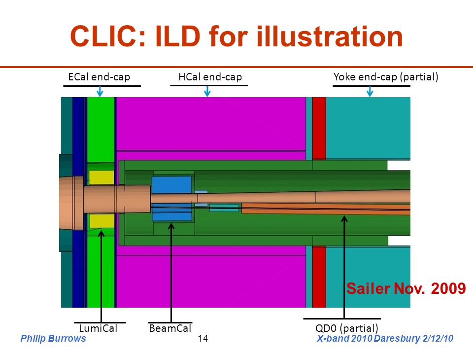
Philip Burrows X-band 2010 Daresbury 2/12/1014 ECal end-capHCal end-capYoke end-cap (partial) LumiCalBeamCalQD0 (partial) CLIC: ILD for illustration Sailer Nov. 2009
15
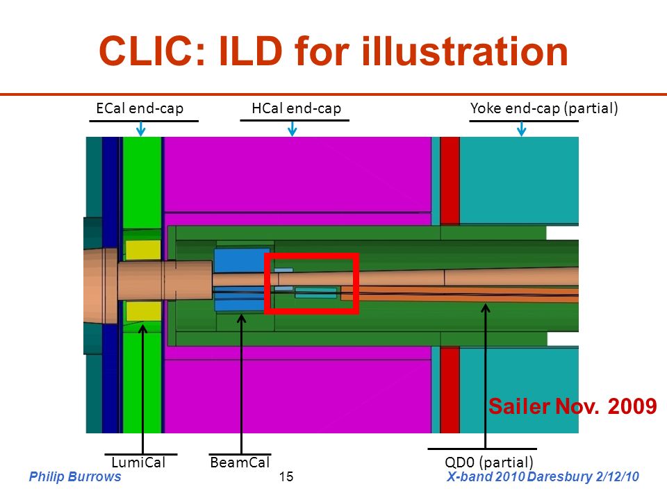
Philip Burrows X-band 2010 Daresbury 2/12/1015 ECal end-capHCal end-capYoke end-cap (partial) LumiCalBeamCalQD0 (partial) CLIC: ILD for illustration Sailer Nov. 2009
16
Philip Burrows X-band 2010 Daresbury 2/12/1016 4 Dec. 2009 8th MDI meeting H.Gerwig Herve 12/2/10 CLIC: zoom-in to QD0

17
Philip Burrows X-band 2010 Daresbury 2/12/1017 Prototyping status

18
Philip Burrows X-band 2010 Daresbury 2/12/1018 KickerBPM 1 Feedbac k processo r Analogue BPM processor Drive amplifier BPM 2 BPM 3 e- Generic prototype layout

19
Philip Burrows X-band 2010 Daresbury 2/12/1019 CLIC-relevant: all-analogue systems Brief prototype history: CLIC

20
Philip Burrows X-band 2010 Daresbury 2/12/1020 KickerBPM 1 Analogu e feedback Analogue BPM processor Drive amplifier BPM 2 BPM 3 e- Generic prototype layout: CLIC

21
Philip Burrows X-band 2010 Daresbury 2/12/1021 CLIC-relevant: all-analogue systems NLCTA (SLAC): 65 MeV beam, 170ns train, 87ps bunch spacing FONT1 (2001-2): First demonstration of closed-loop FB: latency 67ns 10/1 beam position correction FONT2 (2003-4): Improved demonstration of FB: latency 54ns real time charge normalisation with logarithmic amplifiers beam flattener to straighten train profile solid-state amplifier ATF (KEK): 1.3 GeV beam, 56ns train, 2.8ns bunch spacing FONT3 (2004-5): Ultra-fast demonstration of FB: latency 23 ns 3 stripline BPMs high-power solid-state amplifier Brief prototype history: CLIC
: 65 MeV beam, 170ns train, 87ps bunch spacing FONT1 (2001-2): First demonstration of closed-loop FB: latency 67ns 10/1 beam position correction FONT2 (2003-4): Improved demonstration of FB: latency 54ns real time charge normalisation with logarithmic amplifiers beam flattener to straighten train profile solid-state amplifier ATF (KEK): 1.3 GeV beam, 56ns train, 2.8ns bunch spacing FONT3 (2004-5): Ultra-fast demonstration of FB: latency 23 ns 3 stripline BPMs high-power solid-state amplifier Brief prototype history: CLIC")
22
Philip Burrows X-band 2010 Daresbury 2/12/1022 FONT2 beamline installation at SLAC NLCTA (65 MeV 170ns-long train @ 87ns spacing) Dipole and kickers BPMs
 Dipole and kickers BPMs")
23
Philip Burrows X-band 2010 Daresbury 2/12/1023 FONT: kicker driver amplifiers FONT1 3-stage tube amplifier FONT3 PCB amplifer + FB Same drive power as needed for CLIC

24
Philip Burrows X-band 2010 Daresbury 2/12/1024 FONT2 results Feedback on Beam flattener on Beam starting positions Delay loop on beam startbeam end 123 4

25
Philip Burrows X-band 2010 Daresbury 2/12/1025 CLIC-relevant: all-analogue systems FONT2 (2003-4): latency 54ns would allow about 2 correction passes for CLIC 150ns train Brief prototype history: CLIC
: latency 54ns would allow about 2 correction passes for CLIC 150ns train Brief prototype history: CLIC")
26
Philip Burrows X-band 2010 Daresbury 2/12/1026 FONT3: latency budget Time of flight kicker – BPM: 4ns Signal return time BPM – kicker: 6ns Irreducible latency: 10ns BPM processor: 5ns Amplifier + FB: 5ns Electronics latency: 10ns Total latency budget: 20ns Allows 56/20 = 2.8 periods during bunchtrain

27
Philip Burrows X-band 2010 Daresbury 2/12/1027 Fast analogue signal processors 2005 2007 2006

28
Philip Burrows X-band 2010 Daresbury 2/12/1028 FONT3: kicker driver amplifier Same drive power as needed for CLIC

29
Philip Burrows X-band 2010 Daresbury 2/12/1029 FONT3: BPM processor + amplifier/feedback installation in ATF beamline BPM processor board Amplifier/FB board FEATHER kicker

30
Philip Burrows X-band 2010 Daresbury 2/12/1030 FONT3: Beamline Installation

31
Philip Burrows X-band 2010 Daresbury 2/12/1031 FONT3: Results (June 2005) : Delay-loop feedback w. latency 23 ns 56ns bunchtrain FB on FB + delay loop on 23ns 200um

32
Philip Burrows X-band 2010 Daresbury 2/12/1032 CLIC prototype: Summary 67 ns 54 ns 23 ns

33
Philip Burrows X-band 2010 Daresbury 2/12/1033 CLIC-relevant: all-analogue systems FONT3 (2005): total latency 23ns, of which 13ns electronics translates to about 37ns at CLIC would allow about 3 correction passes for CLIC 150ns train basic principle demonstrated: more work needed to optimise design + system performance. Brief prototype history: CLIC

34
Philip Burrows CLIC Technical Committee 23/02/1034 Beam tracking simulations (Javier Resta Lopez) Macroparticle tracking through the BDS using the code PLACET Luminosity calculation using the code Guinea-Pig Ground motion: –In the following simulations we apply 0.02 s (corresponding to f rep =50 Hz) of GM (A. Seryi’s models) to the CLIC BDS –What is the RMS vertical beam-beam offset at the IP we have to deal with? Simulation of 100 random seeds:
 to the CLIC BDS –What is the RMS vertical beam-beam offset at the IP we have to deal with. Simulation of 100 random seeds:.")
35
Philip Burrows CLIC Technical Committee 23/02/1035 Luminosity performance with IP FB Simulation time structure: Example applying a single random seed of GM C

36
Philip Burrows CLIC Technical Committee 23/02/1036 CLIC luminosity result with IP FB For quiet sites: The generated IP-jitter is relatively small after 0.02 s of GM Model A: Without any correction: mean L/L 0 train =99.88% With IP-FB: mean L/L 0 train =99.97% std reduced by a factor 2 Model B: Without any correction: mean L/L 0 train =91.1% With IP-FB: mean L/L 0 train =97.86% std reduced by a factor 4

37
Philip Burrows CLIC Technical Committee 23/02/1037 For noisy sites: In these cases significant luminosity degradation Model C: Without any correction: mean L/L 0 train =30.52% & High standard deviation! With IP-FB: mean L/L 0 train =64.15% std reduced by a factor 2 Model K: Without any correction: mean L/L 0 train =32.53% & High standard deviation! With IP-FB: mean L/L 0 train =67.82% std reduced by a factor 3 CLIC luminosity result with IP FB

38
Philip Burrows X-band 2010 Daresbury 2/12/1038 ILC-relevant: digital feedback processor Brief prototype history: ILC

39
Philip Burrows X-band 2010 Daresbury 2/12/1039 KickerBPM 1 Digital feedback Analogue BPM processor Drive amplifier BPM 2 BPM 3 e- Generic prototype layout: ILC

40
Philip Burrows X-band 2010 Daresbury 2/12/1040 ILC-relevant: digital feedback processor ATF (KEK): 1.3 GeV beam, 3-bunch train, bunch spacing c. 150ns FONT4 / ATF (2006-9): First digital system (Virtex 4): latency 148 ns high-power solid-state amplifier (pulse length up to 10us) FONT5 / ATF2 (2009-10): Faster system (Virtex 5): latency 133 ns coupled-loop system correction of y and y’ 3 BPMs and 2 kickers Brief prototype history: ILC
: First digital system (Virtex 4): latency 148 ns high-power solid-state amplifier (pulse length up to 10us) FONT5 / ATF2 ( ): Faster system (Virtex 5): latency 133 ns coupled-loop system correction of y and y’ 3 BPMs and 2 kickers Brief prototype history: ILC.")
41
Philip Burrows X-band 2010 Daresbury 2/12/1041 KickerBPM 1 Digital feedback Analogue BPM processor Drive amplifier BPM 2 BPM 3 e- FONT4 ILC prototype at KEK/ATF

42
Philip Burrows X-band 2010 Daresbury 2/12/1042 FONT4 basic operation demonstrated in 2008 running: FONT4 results

43
Philip Burrows X-band 2010 Daresbury 2/12/1043 FONT4 basic operation demonstrated in 2008 running: beam feedback along single axis (y) with few micron resolution FONT4 results
 with few micron resolution FONT4 results")
44
Philip Burrows X-band 2010 Daresbury 2/12/1044 FONT5 location

45
Philip Burrows X-band 2010 Daresbury 2/12/1045 Flexible operation mode QD10XQF11XQD12XQD14XQF13XQF15XK1K2 P2P3P1 To dump FB board DAQ P2 K1 (‘position’) P3 K2 (‘angle’) P3 K1
 P3 K2 (‘angle’) P3 K1")
46
Philip Burrows X-band 2010 Daresbury 2/12/1046 FONT5 hardware 3 new BPMs and 2 new kickers installed in new ATF2 extraction line February 2009

47
Philip Burrows X-band 2010 Daresbury 2/12/1047 Valencia FONT BPM movers

48
6 New FONT5 digital FB board Xilinx Virtex5 FPGA 9 ADC input channels (TI ADS5474) 4 DAC output channels (AD9744) Clocked at 357 MHz phase-locked to beam 4x faster than FONT4
 4 DAC output channels (AD9744) Clocked at 357 MHz phase-locked to beam 4x faster than FONT4")
49
Philip Burrows X-band 2010 Daresbury 2/12/1049 One damping ring cycle (463ns) data returned each pulse: RS232 over ethernet All BPM sum (charge) and difference signals Absolute sample time adjustable in 70ps taps: accurate peak sampling Ratio of difference to sum peaks gives y-position Pedestal subtraction w. on-board trim DACs (no latency gain) FONT5 DAQ
 FONT5 DAQ.")
50
6 FONT5 latency: P2 K1 loop (February 2010) Latency 133ns
 Latency 133ns")
51
Philip Burrows X-band 2010 Daresbury 2/12/1051 Latency estimate

52
6 P2 K1 loop performance (February 2010) With banana correction
 With banana correction")
53
6 P2 K1 loop performance (February 2010) Incoming position scan
 Incoming position scan")
54
P2 K1 loop jitter reduction (April 2010) Bunch 1 Bunch 2 Bunch 3 2.1 um 0.4 um 0.8 um Factor of 5 jitter reduction
 Bunch 1 Bunch 2 Bunch um 0.4 um 0.8 um Factor of 5 jitter reduction")
55
Philip Burrows JAI Advisory Board, RHUL 26/04/1055 0.4 micron jitter propagation from P2 P2 Y [micron]
![Philip Burrows JAI Advisory Board, RHUL 26/04/ micron jitter propagation from P2 P2 Y [micron]](http://images.slideplayer.com/47/11726307/slides/slide_55.jpg "Philip Burrows JAI Advisory Board, RHUL 26/04/ micron jitter propagation from P2 P2 Y [micron]")
56
Philip Burrows JAI Advisory Board, RHUL 26/04/1056 Jitter comparison at IP 4 Counts Assuming perfect lattice, no further imperfections (!)
")
57
Philip Burrows JAI Advisory Board, RHUL 26/04/1057 FB correction vs. gain (April 2010)
")
58
6 Feedback removes bunch correlations (April 2010) Bunch 1 Bunch 2 Bunch 3
 Bunch 1 Bunch 2 Bunch 3")
59
Bunch correlations vs. gain (April 2010) Bunch 1-2 Correl.
 Bunch 1-2 Correl.")
60
Philip Burrows JAI Advisory Board, RHUL 26/04/1060 FB simulation: P2-K1+P3-K2 coupled Bunch 1 Bunch 2

61
Coupled loop jitter reduction (May 2010) Bunch 1 Bunch 2 Bunch 3 9.4 um 5.6 um 4.4 um
 Bunch 1 Bunch 2 Bunch um 5.6 um 4.4 um")
62
Philip Burrows X-band 2010 Daresbury 2/12/1062 Summary IP feedback concept well advanced Conceptually-engineered designs for ILC + CLIC All-analogue prototypes (CLIC) developed and tested at NLCTA + ATF: electronics latency c. 13ns Digital prototypes developed and tested at ATF + ATF2: electronics latency c. 90ns To do: real engineering + component optimisation radiation hardness, EM interference …

63
Philip Burrows JAI Advisory Board, RHUL 26/04/1063 Other CLIC possibilities Fast amplifier prototype for drive beam phase instability feed-forward system: 10 deg capture range 0.2 deg phase stability +-375urad max. beam deflection very serious thought and R&D needed prototyping and tests at CTF3?

64
Philip Burrows JAI Advisory Board, RHUL 26/04/1064 CLIC drive beam phase FF

65
A Preliminary System Concept 65C.Perry – Oxford – 15 Oct 2010 - 4 kickers at each bend - 250kW peak power amplifier to each kicker - 256 amplifier modules in each amplifier - 1.2kW output each amplifier module (1kW after losses in combining etc) - 16 amplifiers & kickers / drive beam, 768 amplifiers total, 200MW total peak power dipole magnet 1m kicker 250kW amp 8m5m 8m NOT TO SCALE
 - 16 amplifiers & kickers / drive beam, 768 amplifiers total, 200MW total peak power dipole magnet 1m kicker 250kW amp 8m5m 8m NOT TO SCALE")
66
Philip Burrows CLIC Technical Committee 23/02/1066 FONT3: Results (June 2005) 40 pulses per position setting
 40 pulses per position setting")
67
Philip Burrows JAI Advisory Board, RHUL 26/04/1067 Example: BPM calibrations

68
6 Example: kicker calibration Kick of 40 urad

69
Philip Burrows X-band 2010 Daresbury 2/12/1069 4 Dec. 2009 8th MDI meeting H.Gerwig Herve 22/2/10 CLIC: zoom-in to QD0

70
Philip Burrows X-band 2010 Daresbury 2/12/1070 4 Dec. 2009 8th MDI meeting H.Gerwig Herve 22/2/10 CLIC: zoom-in to QD0

71
Philip Burrows CLIC Technical Committee 23/02/1071 Luminosity results summary SVD orbit correction BPM resolution ~100 nm Simulate effect of IP feedback and slow orbit FB in BDS

Similar presentations
 10 th ATF Project Meeting.>")


: FONT2 December 2003 run results Philip Burrows.>")
 for the FONT project group FONT meeting January 11, 2007.>")


 for the FONT project group FONT meeting January 25, 2008.>")
 Philip Burrows John Adams Institute Oxford University EM Background Tests of Feedback BPM.>")


 – Demonstration of a compact final focus.>")

: Philip Burrows Neven Blaskovic, Douglas Bett*, Talitha Bromwich, Glenn Christian, Michael Davis, Colin Perry.>")

: FONT2 run results Dec 03/Jan 04 Philip Burrows Queen Mary, University.>")

 for the FONT project group 5th ATF2 project meeting, KEK December 19-21, 2007.>")