Download presentation
Presentation is loading. Please wait.

1
CONTROL AND SAFETY of Nuclear Steam Supply Systems (NSSS)
")
2
Literature: Paul Reuss. Neutron Physics. Nuclear physics and reactor theory. Doe fundamental handbook. Vol. 1 and 2. Geoffrey F. Hewitt, John G. Collier. Introduction to Nuclear Power. Yoshiaki Oka, Katsuo Suzuki. Nuclear Reactor Kinetics and Plant Control. J.G. Tiror, R.I. Vaughan. An Introduction to the Neutron Kinetics of Nuclear Power Reactors

3
Introduction The basis of technical safety is a nuclear power reactor design. The design of fuel elements, fuel assembly, the design of the entire core, the design of vessel equipment provide not only normal operation, but also play the role of the main protective barriers of nuclear power plants. The design of the core and reactor laid at the design stage affect the viability and safety of the entire plant. Of course, the design of main equipment included in various nuclear power technological systems is critical to the safe operation of NPP.

4
However, in emergency situations in case of failure of the main equipment, or even in case of serious damage in its construction when the internal safety features of NPP cannot cope with the consequences of an emergency, it is important to provide specific safety systems that minimize the consequences of influence of the accident on technical condition of the equipment and ecological situation at the nuclear power plant and around it.

5
The operation of these systems in emergency situations should lead primarily to preserve the integrity of main safety barriers: fuel, fuel cladding, reactor vessel and a protective dome of power generating unit. In the second place, when the integrity of one of the NPP protective barriers is disrupted, safety systems minimize the consequences of these disruptions.

6
Safety systems in its operation are divided into active and passive systems. Active systems have some facilities (usually pumps) in its structure which are turned on in the event of an emergency and provide safety of the equipment. Passive systems have no facilities to be turned on in case of the accident. The accident itself, at its start, drives the work of passive safety systems.
 in its structure which are turned on in the event of an emergency and provide safety of the equipment. Passive systems have no facilities to be turned on in case of the accident. The accident itself, at its start, drives the work of passive safety systems..")
7
For example, the accident with blackout results in the opening of the electromagnetic latches on the actuators of control and protection system and in falling of absorbing rods into the core by gravity. It provides a subcriticality of a reactor and neutron power reduction to zero.

8
The second example is the accident with pressure reduction in the reactor due to the different kind of leakage from the 1 st circuit. With a certain pressure value (5.9 MPa), check valves open on the highways connecting the reactor with passive system and the water under the action of its gravity starts to flow into the reactor and provide cooling of the core.
, check valves open on the highways connecting the reactor with passive system and the water under the action of its gravity starts to flow into the reactor and provide cooling of the core..")
9
If pressure drop in the 1st circuit stops, the flow of water from the system of emergency cooling of the reactor core will also stop. This is because when water flows out of tanks, the amount water and pressure of nitrogen cushion in them decrease, which leads to the disappearance of the pressure differential on the check valve, i.e. the given system has the property of a complete self-regulation.

10
Structure of the main equipment and systems of normal operation of NPP with VVER-1000 The main equipment and systems of normal operation of the reactor plant VVER-1000 are designed for technological processes of normal operation, i.e. heating, power ascension, power operation, shutdown, cooldown and refueling.

11
The structure of the main equipment and systems of normal operation of NPP with VVER-1000 includes: reactor; main circulation circuit and pressure compensation system; control and protection system and monitoring and diagnostics systems; feed and bleed system of the first circuit, including boron control; fuel handling, storing and transport system; steam generators and system of steam piping and feed pipelines of high pressure of the second circuit; system of radiation protection.

12
2. Reactor A reactor is designed for generating heat energy in a reactor facility of the nuclear power plant. VVER-1000 reactor is a water-water power reactor of the vessel type.

13
Coolant and moderator in the reactor is chemically demineralized water with boric acid, the concentration of which varies in use. When passing through the fuel assembly, coolant is heated by the fission of nuclear fuel. The coolant is forced into the reactor through four vessel inlet nozzles (three - at some Western nuclear power plants with the PWR, six - at NPP with VVER-440), passes through annular space between the vessel and in-vessel cavity through a perforated elliptical bottom and supporting pipes of the cavity and enters fuel assembly.
, passes through annular space between the vessel and in-vessel cavity through a perforated elliptical bottom and supporting pipes of the cavity and enters fuel assembly..")
14
From the fuel assembly through the perforated bottom plate of the protective tube units (PTU), coolant goes out to the annular distance of PTU, to the annular space between the cavity and vessel and through 4 vessel outlet nozzles (3…6) goes out of the reactor. The reactor design is shown in Fig. 2.1. It shows a sectional drawing of the reactor with overall dimensions of main reactor elements.

15
Main equipment of the reactor: core; reactor vessel (which is also a part of the 1 st circuit system); in-vessel internals and upper unit of trailer coupling mechanisms; assembly of neutron measurement channels; mechanical controls and protection system and stepping electromagnetic drive of CPS.
; in-vessel internals and upper unit of trailer coupling mechanisms; assembly of neutron measurement channels; mechanical controls and protection system and stepping electromagnetic drive of CPS.")
17
3. Core VVER-1000 core is made of fuel assemblies (FA) of hexagonal shape on a hexagonal grid with a constant pitch of about 200-240 mm (for PWR - made of square fuel assemblies on a square grid).
 of hexagonal shape on a hexagonal grid with a constant pitch of about mm (for PWR - made of square fuel assemblies on a square grid)..")
18
The number of fuel assemblies in the core is determined by their dimensions and capacity of the reactor, as well as transportable properties of the vessel equipment by railway in our country.

19
When forming the core, it is important to determine dimensions and material composition of the fuel assembly (FA) and fuel elements in it. The maximum size of the fuel assembly is limited by the requirements of nuclear safety for the inadmissibility of a critical mass in a fuel assembly, and minimum - economic considerations (the larger the fuel assembly, the cheaper the core).
..")
20
In the course of various studies, for VVER- 1000 reactor one chose a fuel assembly with a pitch of the same size as a wrench on a hexagonal grid, equal to 234 mm (in western analogues such pitch on a square grid is equal to about 205 mm). For VVER-1000, it is enough to have 163 fuel assemblies.

21
Fuel assembly for VVER generally consists of fuel element array, some of which are replaced by non-fuel elements, which may be tubes for absorbing element of CPS or rods with burnable absorber. Fig. 2.2 shows schematically main elements of the fuel assembly

22
Fig. 1 shows configurations of the core and fuel assemblies of VVER-1000 reactor. Core (163 FA)FA (312 FE)
FA (312 FE).")
23
Below, when considering the structural characteristics of VVER-1000 reactor core, the characteristics of PWR core (on the example of Gösgen) are given for comparison.
 are given for comparison.")
24
Fig. 2 shows configurations of the core and fuel assemblies of PWR for Gösgen NPP located in Sweden. Core (49 FA) FA (177 FE)
 FA (177 FE).")
25
In VVER-1000 reactor, fuel assembly is a structure assembled from fuel and other structural elements arranged on a hexagonal grid with a constant pitch of fuel assemblies. In PWR reactor fuel assembly is a structure assembled from fuel and other structural elements arranged on a square grid with a constant pitch of fuel assemblies.

26
In the most intense FA, fuel enrichment profiling is used for flattering of energy release of fuel assembly, consisting in placing of about 66 fuel elements with lower enrichment than the other fuel rods along the FA perimeter. In the West, our colleagues do the same for flattering of energy release by FA section of PWR. Profiling reduces energy release of fuel assembly at the junction between the peripheral row of FA and next row in the core and increases thermo- technical safety of the core.

28
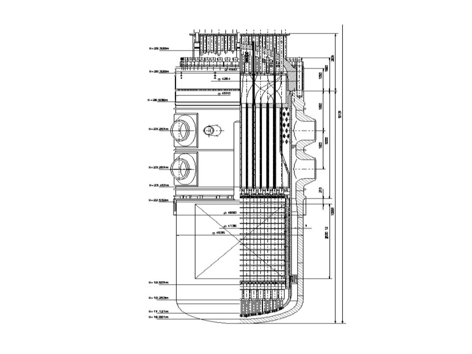
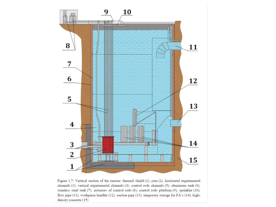
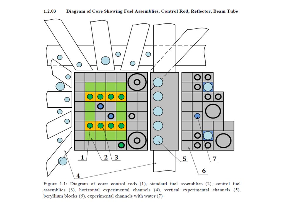
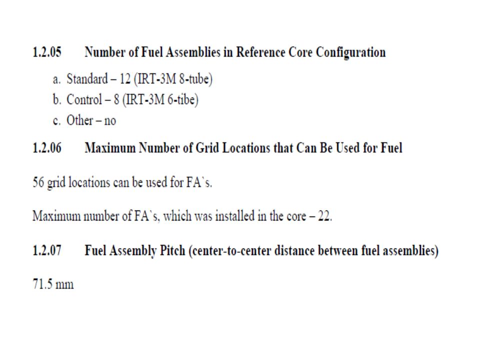
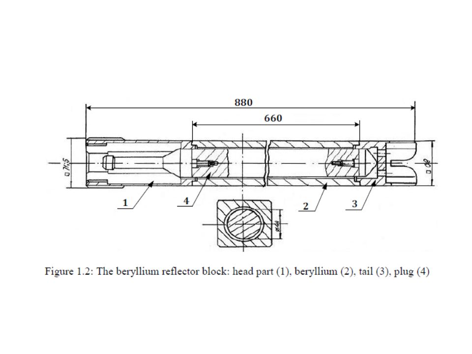
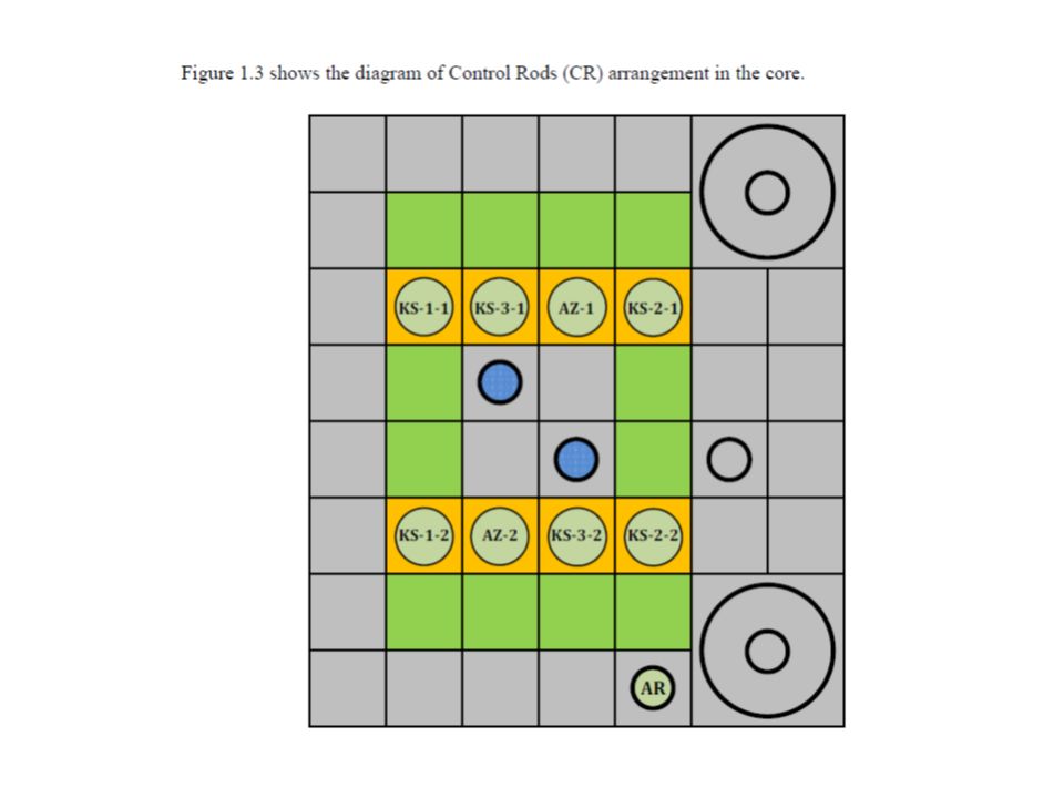
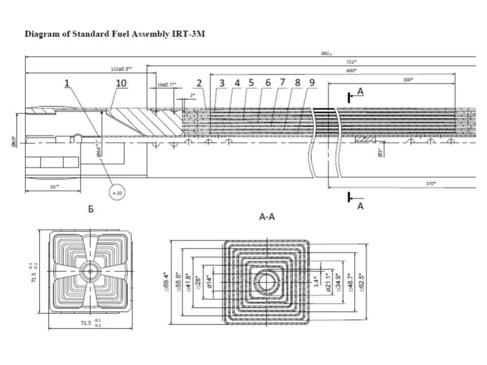
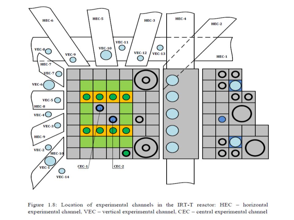
REACTOR IRT-T is a pool type research reactor.

Similar presentations


: Safety Systems Overview>")

 Covered Keywords Pressurized Water Reactor (PWR), Boiling Water Reactor (BWR), primary loop, reactivity, reactivity control, reactivity.>")


 Covered Keywords Containment Isolation, actuation logic, Description Supporting Material 1.2.1.53.3.2.4.24.10.4.25.3.2.75.4.3.11.>")