Download presentation
Presentation is loading. Please wait.

1
10.1 Single-bit error

2
A burst error means that 2 or more bits in the data unit have changed. Note:

3
10.2 Burst error of length 5

4
Error detection uses the concept of redundancy, which means adding extra bits for detecting errors at the destination. Note:

5
10.3 Redundancy

6
10.4 Detection methods

7
In parity check, a parity bit is added to every data unit so that the total number of 1s is even (or odd for odd-parity). Note:

8
Example 1 Suppose the sender wants to send the word world. In ASCII (7-bit code) the five characters are coded as 1110111 1101111 1110010 1101100 1100100 Even parity is used. The following shows the actual bits sent: 11101110 11011110 11100100 11011000 11001001
 the five characters are coded as Even parity is used. The following shows the actual bits sent:")
9
Example 3 Now suppose the word world in Example 1 is received by the receiver without being corrupted in transmission. 11101110 11011110 11100100 11011000 11001001 The receiver counts the 1s in each character and comes up with even numbers (6, 6, 4, 4, 4). The data are accepted. Now suppose the word world in Example 1 is corrupted during transmission. 11111110 11011110 11101100 11011000 11001001 The receiver counts the 1s in each character and comes up with even and odd numbers (7, 6, 5, 4, 4). The receiver knows that the data are corrupted, discards them, and asks for retransmission.
. The data are accepted. Now suppose the word world in Example 1 is corrupted during transmission The receiver counts the 1s in each character and comes up with even and odd numbers (7, 6, 5, 4, 4). The receiver knows that the data are corrupted, discards them, and asks for retransmission..")
10
Simple parity check can detect all single-bit errors. It can detect burst errors only if the total number of errors in each data unit is odd. Note:

11
In two-dimensional parity check, a block of bits is divided into rows and a redundant row of bits is added to the whole block. Note:

12
10.6 Two-dimensional parity

13
Example 4 Suppose the following block is sent: 10101001 00111001 11011101 11100111 10101010 However, it is hit by a burst noise of length 8, and some bits are corrupted. 10100000 00001001 11011101 11100111 10101010 When the receiver checks the parity bits, some of the bits do not follow the even-parity rule and the whole block is discarded. 10100000 00001001 11011101 11100111 10101010

14
10.7 CRC generator and checker CRC = Cyclic Redundency Check

15
”Vanlig” division 17. 1 5 2 5 0 3 Haltande liknelse med CRC: Om vi subtraherar täljaren (17) med resten (2) vi ett tal som är jämnt delbart med nämnaren (5). Om mottagaren tar emot något som inte är delbart med 5 har sannolikt att bitfel uppstått. (Nämnare) Nominator (Täljare) Reminder (Rest) (Kvot)
 med resten (2) vi ett tal som är jämnt delbart med nämnaren (5). Om mottagaren tar emot något som inte är delbart med 5 har sannolikt att bitfel uppstått. (Nämnare) Nominator (Täljare) Reminder (Rest) (Kvot).")
16
Modulo 2 Arithmetic qIn modulo 2 arithmetic addition and substruction are identical to EXCLUSUVE OR (XOR) operation. qMultiplication and division are the same as in base-2 arithmetic without carries in addition or borrows in substraction. 0 XOR 0 = 0 0 XOR 1 = 1 1 XOR 0 = 1 1 XOR 1 = 0 Examples: 1011 XOR 0101 = 1110 1001 XOR 1101 = 0100

17
10.8 Binary division in a CRC generator The number of 0s is one less than the number of bits in G (divisor)
")
18
10.8 Binary division in a CRC generator The first bit in the quotient is 1 and one times the divisor results in this Obtained by XOR-ing 1001 and 1101 The first bit in the numerator is 1. Then the first bit in the quotient is 1.

19
10.8 Binary division in a CRC generator Transmitted data: 1 0 0 1 0 0 0 0 1

20
10.9 Binary division in CRC checker

21
Another Example The transmitted data is 11010110111110

22
10.11 A polynomial representing a divisor 7th order polynomial 8 bit divisor

23
Polynomyal representation qBased upon discrete mathetematics, where bit strings are treated as polynomials. qk bit divisor is represented as (k-1) degree polynomial with coefficients 0 and 1. qExample: 1010110 has 7 bits qIt can be represented as a polynomial of 6 th degree 1·x 6 + 0·x 5 + 1·x 4 +0·x 3 + 1·x 2 + 1·x 1 + 0·x 0 = x 6 + x 4 + x 2 + x
 degree polynomial with coefficients 0 and 1. qExample: has 7 bits qIt can be represented as a polynomial of 6 th degree 1·x 6 + 0·x 5 + 1·x 4 +0·x 3 + 1·x 2 + 1·x 1 + 0·x 0 = x 6 + x 4 + x 2 + x.")
24
Table 10.1 Standard polynomials NamePolynomialApplication CRC-8x 8 + x 2 + x + 1ATM header CRC-10x 10 + x 9 + x 5 + x 4 + x 2 + 1ATM AAL ITU-16x 16 + x 12 + x 5 + 1HDLC ITU-32 x 32 + x 26 + x 23 + x 22 + x 16 + x 12 + x 11 + x 10 + x 8 + x 7 + x 5 + x 4 + x 2 + x + 1 LANs

25
Example 5 It is obvious that we cannot choose x (binary 10), x 2 (binary 100), etc, because then the reminder is 0. We cannot chose a polynomial that is divisible by x, for example x 2 + x (binary 110). However, we can choose x + 1 (binary 11) because it is not divisible by x, but is divisible by x + 1. We can also choose x 2 + 1 (binary 101) because it is divisible by x + 1 (binary division).
. However, we can choose x + 1 (binary 11) because it is not divisible by x, but is divisible by x + 1. We can also choose x (binary 101) because it is divisible by x + 1 (binary division)..")
26
How CRC Operates qThe sender wants to send k bits message qThe sender and the receiver must agree in advance on n+1 bit string called generator polynomial (divisor), G. mG can be represented as n-degree polynomial qn redundant bits are added to the k bits message. They are called CRC bits. Data bits to be sent CRC bits k bitsn bits

27
How CRC Operates (Cont.) qThe redundant bits are chosen in such a way that the resulting k+n bit string is exactly divisible (with a reminder=0) by G using modulo 2 arithmetic. qThe receiver divides the received data together with the CRC bits by G using modulo 2 arithmetic. mIf the reminder is 0, then the string is considered to be without errors mIf the reminder is not 0, the data unit is with errors and it is rejected

28
Example 6 The CRC-12 x 12 + x 11 + x 3 + x + 1 which has a degree of 12, will detect all burst errors affecting an odd number of bits, will detect all burst errors with a length less than or equal to 12, and will detect, 99.97 percent of the time, burst errors with a length of 12 or more.

29
Example 6.7: CRC

31
The sender follows these steps: The unit is divided into k sections, each of n bits.The unit is divided into k sections, each of n bits. All sections are added using one’s complement to get the sum.All sections are added using one’s complement to get the sum. The sum is complemented and becomes the checksum.The sum is complemented and becomes the checksum. The checksum is sent with the data.The checksum is sent with the data. Note:

32
Example 10 1 1 1 1 00110 10001 11001 10111 1000111 10 01001 10110 qn=5 bit checksum. q20 bit data gives k=20/n=4 sections (rows). qThe addition starts in the last column. qThe bits are carried in the columns before. qThe 6 th and 7 th bit are added qThe sum is complemented Carry from column 1 Column: 7 6 5 4 3 2 1 Carry from column 2 Carry from column 3 Carry from column 4 Carry from column 5 Sum Checksum
. qThe addition starts in the last column. qThe bits are carried in the columns before. qThe 6 th and 7 th bit are added qThe sum is complemented Carry from column 1 Column: Carry from column 2 Carry from column 3 Carry from column 4 Carry from column 5 Sum Checksum.")
33
Example 7 Suppose the following block of 16 bits is to be sent using a checksum of 8 bits. 10101001 00111001 The numbers are added using one’s complement 10101001 00111001 ------------ Sum 11100010 Checksum 00011101 The pattern sent is 10101001 00111001 00011101

34
The receiver follows these steps: The unit is divided into k sections, each of n bits.The unit is divided into k sections, each of n bits. All sections are added using one’s complement to get the sum.All sections are added using one’s complement to get the sum. The sum is complemented.The sum is complemented. If the result is zero, the data are accepted: otherwise, rejected.If the result is zero, the data are accepted: otherwise, rejected. Note:

35
Example 8 Now suppose the receiver receives the pattern sent in Example 7 and there is no error. 10101001 00111001 00011101 When the receiver adds the three sections, it will get all 1s, which, after complementing, is all 0s and shows that there is no error. 10101001 00111001 00011101 Sum11111111 Complement 00000000 means that the pattern is OK.

36
Example 9 Now suppose there is a burst error of length 5 that affects 4 bits. 10101111 11111001 00011101 When the receiver adds the three sections, it gets 10101111 11111001 00011101 Partial Sum 1 11000101 Carry 1 Sum 11000110 Complement 00111001 the pattern is corrupted.

37
11.1 Flow and Error Control Flow Control (Flödesstyrning) Error Control (Felhantering) Båda dessa funktioner hanteras av vissa datalänkprotokoll (lager 2), i LLC-sublagret, t.ex. vid trådlös kommunikation eller vid modem. End-to-end flödesstyrning och felkontroll hanteras av transportprotokollet TCP (lager 4).
..")
38
Flow control Necessary when data is being sent faster than it can be processed by receiver to avoid that the receiver’s buffer is overwhelmed.

39
Felhantering med hjälp av felrättande koder FEC = Forward Error Correction. Baseras på felrättande istället för felupptäckande koder. Kräver ingen backkanal. Två typer: 1.Faltningskoder (convolutional codes). Ex:Vid Faltningskod med kodtakt (code rate) 1/3 infogas två redundanta bitar mellan varje bit i nyttomeddelandet. Dessa felrättande bitar beräknas kontinuerligt för varje inkommande bit i nyttomeddelandet. 2.Blockkoder (block codes) Ex: I digital-TV-systemet används en s.k. Read Salomon-kod med beteckningen RS(204, 188, 8). Det innebär att nyttoinformationen delas upp i 188 byte stora block. För varje block beräknas en felrättande kod, som läggs till blocket så att blocket blir 204 byte. Redundanden är alltså 204 – 188 = 16 byte. Koden klarar 8 felaktiga byte.
. Ex:Vid Faltningskod med kodtakt (code rate) 1/3 infogas två redundanta bitar mellan varje bit i nyttomeddelandet. Dessa felrättande bitar beräknas kontinuerligt för varje inkommande bit i nyttomeddelandet. 2.Blockkoder (block codes) Ex: I digital-TV-systemet används en s.k. Read Salomon-kod med beteckningen RS(204, 188, 8). Det innebär att nyttoinformationen delas upp i 188 byte stora block. För varje block beräknas en felrättande kod, som läggs till blocket så att blocket blir 204 byte. Redundanden är alltså 204 – 188 = 16 byte. Koden klarar 8 felaktiga byte..")
40
Felhantering med hjälp av felupptäckande koder Alternativ 1: Bortkastning av felaktiga paket. Alternativ 2: ARQ = Automatic Repeat reQuest = automatisk omsändning av paket vid bitfel, eller om paketet inte når fram. I fortsättning kommer vi med begreppet ”error control” eller ”felkontroll” att avse ARQ.

41
Protocols to be presented qIdle RQ = Stop-and-wait ARQ qSliding Window Flow Control qGo-back-N ARQ qSelective Repeat ARQ Sliding Window Protocols

42
The Idle RQ (Repeat Request) Protocol The simplest protocol for error and flow control How the protocol operates: mSource may not send a new frame until the receiver acknowledges previous one. mThe receiver sends only positive acknowledgements (ACK) to notify the sender that the frame was received. mIf the frame 0 was received, the ACK 1 is sent. In that way the sender is notified that the receiver is expecting frame 1. mThe ID of the frame is called a sequence number. m1 bit sequence numbers is sufficient. Sequence: 0 1 0 1 0....
 to notify the sender that the frame was received. mIf the frame 0 was received, the ACK 1 is sent. In that way the sender is notified that the receiver is expecting frame 1. mThe ID of the frame is called a sequence number. m1 bit sequence numbers is sufficient. Sequence:")
43
Figure 6.23 Idle RQ error control scheme: (a) error free;
 error free;")
44
(b) corrupted I-frame;
 corrupted I-frame;")
45
Figure 6.24 Idle RQ link utilization.

46
(c) corrupted ACK-frame.
 corrupted ACK-frame.")
47
11.1 Normal operation ACK n = Acknowledgement. Expecting frame number n

48
11.2 Stop-and-Wait ARQ, lost frame

49
Lost or Damaged Frame qThe sender starts a timer when it sends each frame qIf the ACK is not received before the timer expires, the sender resends the same frame again

50
11.3 Stop-and-Wait ARQ, lost ACK frame

51
Lost or damaged ACK qLost ACK causes duplicate frames qA duplicate frame is recognized by the sequence number and is discarded qThe receiver sends the same ACK again

52
11.4 Stop-and-Wait ARQ, delayed ACK

53
Numbered acknowledgments are needed if an acknowledgment is delayed and the next frame is lost. Note:

54
Piggybacking qUsually the communication is in both ways – this means that the sender is a receiver and the receiver is the sender, too. (both send and receive data) qTo save on the processing and bandwidth the short ACKs messages are not sent as separate frames. Instead, they may be included in the frames with data. qThis technique is called piggybacking
 qTo save on the processing and bandwidth the short ACKs messages are not sent as separate frames. Instead, they may be included in the frames with data. qThis technique is called piggybacking.")
55
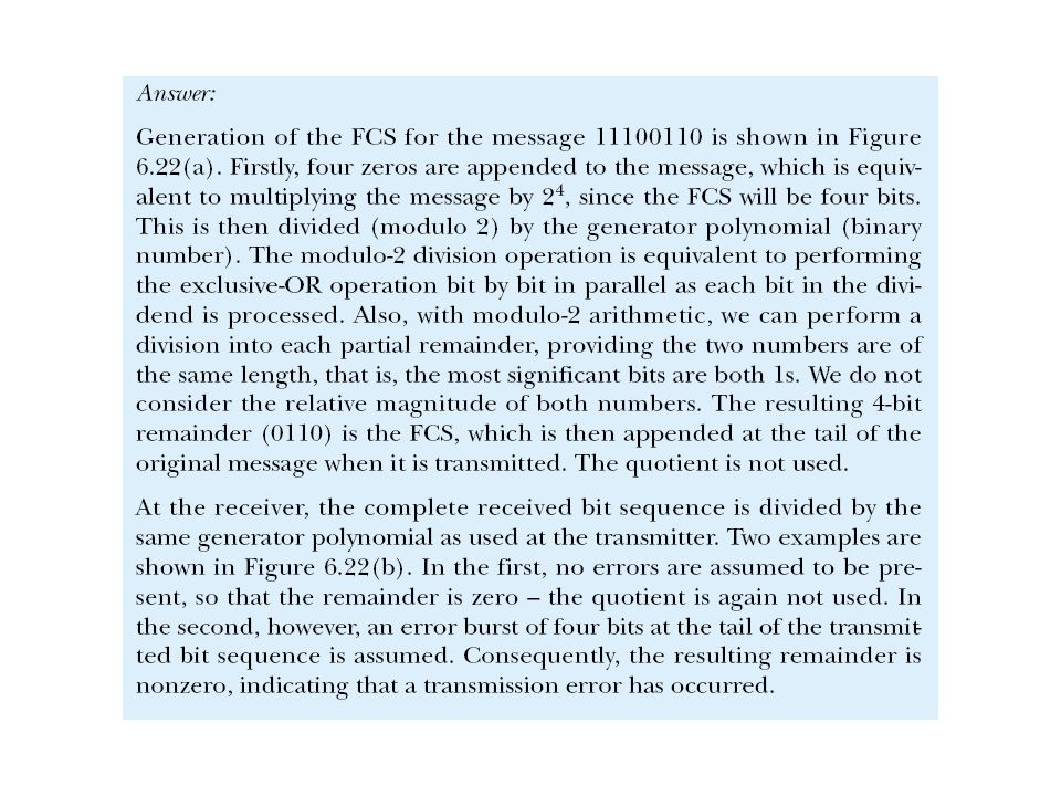
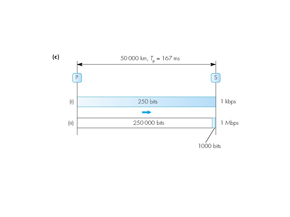
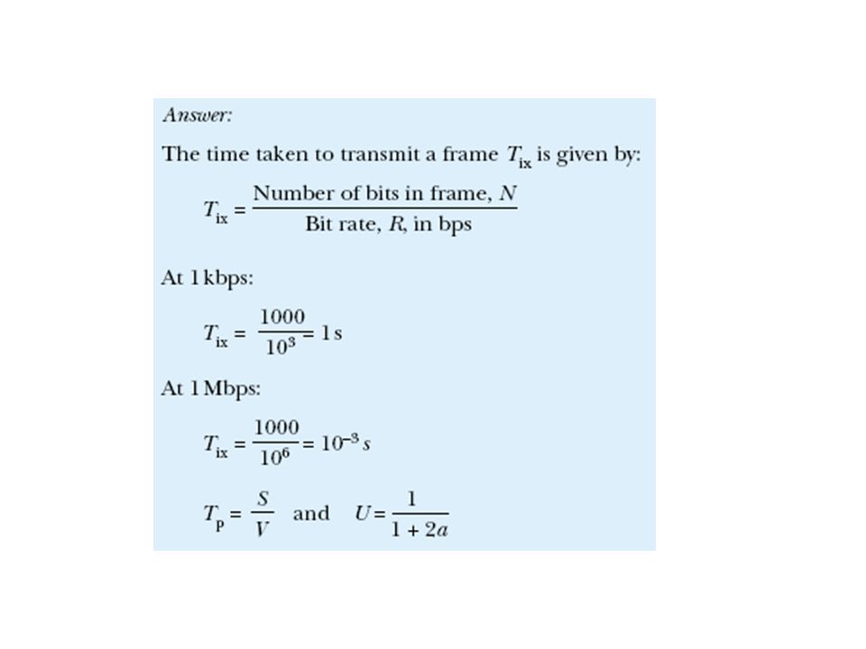
Example 6.8: Idle RQ

56
Figure 6.25 Effect of propagation delay as a function of data transmission rate; parts correspond to Example 6.8.

61
Example 6.9

62
11.5 Piggybacking

63
Efficiency of Stop-and-Wait qVery inefficient, having in mind that most of the time the sender is idle qExample: 40 km copper cable, 10 Mbps rate, 1000 bit frame, mSignal in copper propagates at 2 x 10 8 m/sec mTransmission time is 1000/10000000 (Takes 0.1 msec to transmit frame) mPropagation time is 40000/ 2 x 10 8 (0.2 msec delay to begin arriving at the receiver) mTotal time is 0.3 msec. to get to the receiver mACK transmission time is approximately 0 (assuming the ACK is very short (length 0) m0.2 msec is the time for the ACK to arrive at the sender qTotal time is 0.5 msec before the sender can transmit again q0.5 ms for 0.1 msec frame or efficiency is 20%
 m0.2 msec is the time for the ACK to arrive at the sender qTotal time is 0.5 msec before the sender can transmit again q0.5 ms for 0.1 msec frame or efficiency is 20%.")
64
Sliding-Window flow control qSeveral frames can be sent without acknowledgement being received qN is the window size – the maximum number of frames that can be sent and not being acknowledged. qThe receiver must be able to buffer N frames. qSequence numbers are used to identify each frame. They are carried in the header. qThe number of different sequence numbers must be at least N+1. qIf the field for sequence numbers allows m bits, the number of different sequence number is 2 m and the sequence numbers range from 0 to 2 m -1. In that case the maximum window size is N = 2 m -1.

65
11.6 Sender sliding window The sender window is the the set of frames that may be transmitted before an ACK. It slides when the sender has received an ACK and sent next frame.

66
11.7 Receiver sliding window The receiver window is the the set of frames that may be accepted before the buffer is full. While the buffer is full, the receiver sends no ACK. The window of a stuffed receiver slides when the receiver has ”consumed” a frame and thus sent an ACK.

67
Stop-and-Wait vs. Sliding Window Sender Receiver Frame 0 Frame 1 Frame 0 ACK 0 ACK 1 ACK 0...... Time Sender Receiver...... Time...... Sequence numbers are 1 bit long (0 or 1) Sequence numbers from 0 to 2 m - 1. m-bit field for the seq. num. Transmiss ion time for the packet Transmission + propagation time for the ACK propa- gation time Transmission + propagation time for the packet Frame 0 Frame 1 Frame 2 ACK 1 ACK 2 ACK 3 Frame consumption delay Frame consump- tion delay Window size N=3.
 Sequence numbers from 0 to 2 m - 1. m-bit field for the seq. num. Transmiss ion time for the packet Transmission + propagation time for the ACK propa- gation time Transmission + propagation time for the packet Frame 0 Frame 1 Frame 2 ACK 1 ACK 2 ACK 3 Frame consumption delay Frame consump- tion delay Window size N=3..")
68
Sender and Receiver Prospective The window size is 7

69
Sliding Window Flow Control F0 F1 F2 F4 F5 ACK1 ACK4 ACK6 56701234560123470 56701234560123470 56701234560123470 56701234560123470 56701234560123470 56701234560123470 56701234560123470 56701234560123470 56701234560123470 56701234560123470 56701234560123470 56701234560123470 56701234560123470 56701234560123470 56701234560123470 F3 ACK2ACK3 56701234560123470 56701234560123470 ACK5 N=6

70
ARQ with Sliding Window Problems arise when some of the frames are discarded (errors or lost frames). Two strategies are developed to deal with this problem: qGo-back-N strategy mThe reciever simply discards all frames after the damaged frame without sending acknowledgement. qSelective repeat strategy mThe receiver keeps all the frames after the damaged frame. It sends negative acknowledgement (NACK) for the damaged frame. When the sender finaly notice that something is wrong it retransmits the bad frame. The two strategies are trade-offs between bandwidth and data-link buffer space.
 for the damaged frame. When the sender finaly notice that something is wrong it retransmits the bad frame. The two strategies are trade-offs between bandwidth and data-link buffer space..")
71
Go-Back-N Strategy qIf a frame is lost, the lost frame and all the frames sent after it are sent again. qSending window of size N, receiving window of size 1. qThe sender has to buffer N frames qBandwidth is wasted.

72
11.9 Go-Back-N ARQ, normal operation

73
11.10 Go-Back-N ARQ, lost frame

74
11.11 Go-Back-N ARQ: sender window size

75
Selective Repeat Strategy qOnly retransmit the frames that are in error qBoth sending and receiving window are of size N

76
11.13 Selective Repeat ARQ, lost frame

77
11.14 Selective Repeat ARQ, sender window size

78
Bandwidth – Delay Product qThe product of the bit rate (bandwidth expressed as bits per seconds) and the propagation time gives the number of bits that can be on the channel and thus can give orientation about the window size qWhen propagation time is high (for example in satellite channels), the window size need to be larger
 and the propagation time gives the number of bits that can be on the channel and thus can give orientation about the window size qWhen propagation time is high (for example in satellite channels), the window size need to be larger")
79
Example 1 In a Stop-and-Wait ARQ system, the bandwidth of the line is 1 Mbps, and 1 bit takes 20 ms to make a round trip. What is the bandwidth-delay product? If the system data frames are 1000 bits in length, what is the utilization percentage of the link? Solution The bandwidth-delay product is 1 10 6 20 10 -3 = 20,000 bits The system can send 20,000 bits during the time it takes for the data to go from the sender to the receiver and then back again. However, the system sends only 1000 bits. We can say that the link utilization is only 1000/20,000, or 5%. For this reason, for a link with high bandwidth or long delay, use of Stop-and-Wait ARQ wastes the capacity of the link.

80
Example 2 What is the utilization percentage of the link in Example 1 if the link uses Go- Back-N ARQ with a 15-frame sequence? Solution The bandwidth-delay product is still 20,000. The system can send up to 15 frames or 15,000 bits during a round trip. This means the utilization is 15,000/20,000, or 75 percent. Of course, if there are damaged frames, the utilization percentage is much less because frames have to be resent.

Similar presentations


>")


 without waiting for ACK, up to N outstanding, unACK’ed packets a logically different.>")


