Download presentation
Presentation is loading. Please wait.

1
The new era of Nanotechnology is coming

2
WHAT IS NANOROBOTS???? Nanorobot is a tiny machine designed to perform a specific task repeatedly and with precision at nanoscale dimensions. – 1 Nanometer = 10 -9 meter !!!! BOTS ….. NANO IN SIZE!!

3
Bigger Isn't Always Better – In 1959, Richard Feynman, an engineer at CalTech, issued a challenge to engineers everywhere. He wanted someone to build a working motor that could fit within a cube 1/64th of an inch on each side. His hope was that by designing and building such a motor, engineers would develop new production methods that could be used in the emerging field of nanotechnology. In 1960, Bill McLellan claimed the prize, having built a working motor to the proper specifications. Feynman awarded the prize even though McLellan built the motor by hand without devising any new production methodologies.motor

4
1. MEDICAL NANOROBOT RESEARCH - Quantum Dot new materials - Genome analysis - Biomedical Problems - Microelectronics miniaturization nanoelectronics New research subject: - Interdisciplinary focus Natural result from: Motivation: - Establish Methodologies on System and Device Prototyping - Control and Architecture of Nanorobots for Medicine

5
2. NANOROBOT RESEARCH CHALLENGE a.Architecture, sensing and actuation at nanoscale: - development of molecular nanomachine & systems Possible applications: - Nanoassembly automation - Health care b. An acceptable approach i.Agents as assemblers sensory feedback intelligent control is indispensable for micro/nano manipulation ii.Advanced analytical approach as a tool for exploration and design

6
3. RESEARCH OBJECTIVES a. Methodology: - Establish the necessary tools for the study of nanorobots b. Control: - Identify methodology to control nanorobots c. Architecture: - Investigate issues associated with hardware requirements d. Flow Signal: - Define the chemical / thermal blood flow signals that interferes with sensing and actuation

7
4. RESEARCH METHODOLOGY c. System Identification and Requirements: - System Modular approach to validate nanorobot architecture analysis - Verification Hardware Description Language (VHDL) to verify IC-Layout Architecture simulation a. Characterization of sensor-based events: - Define protein anti-body based signals - Control modelling - nanorobot behaviours b. Biomedical Flow Signal: -Finite Element Method (FEM) to study flow patterns
 to verify IC-Layout Architecture simulation a. Characterization of sensor-based events: - Define protein anti-body based signals - Control modelling - nanorobot behaviours b. Biomedical Flow Signal: -Finite Element Method (FEM) to study flow patterns.")
8
Nanorobot IC Layout * CMOS Can be used as embedded nanodevice to build integrated sensors and actuator for nanorobots CMOS achieved 10nm sizes functionality

9
* CMOS RF-CMOS with wireless communication is a feasible way to interface with nanorobots – tracking, operation, diagnosis Photonics + Q.D. + nanotubes: enable high performance to production of nanodevices Nanorobot IC Layout

10
* CMOS Nanorobot hardware integrated nanocircuit architecture Nanorobot IC Layout Electromagnetic backpropagation waves are used to define the nanorobot positions

11
BUILDING BLOCK OF NANOROBOT CMOS CNT(CARBON NANO TUBES)
")
12
Chemical Nano Sensors Electrofluidic allignment to get multielement system. Passive and buried electrodes can be used to enable cross-section drive. transistors for signal processing circuitry readout. the antibody anti-digoxigenin is included for modelling the IC biosensor. the antibody serves to identify higher concentrations of proteins that couple alpha-NAGA isoforms to intracellular bloodstream signaling

13
Chemical Nano Sensors The nanobiosensor provides an efficient integrated way for nanorobots identifying the locations with occurrences of alpha-NAGA Enzyme secretion from cell hostage produces alpha-NAGA overexpression, which is denoted by changes of gradients in the bloodstream CMOS based nano wire sensor arrays

14
Chemical Nano Sensors Advantages Decrease self heating drastically Efficiently detect chemical changes Low energy consumption High resolution of sensors Extremely small size achieved by 18 nm cmos technology.

15
Chemical Nano Sensors Disadvantage Include quantum-mechanical tunneling for operation of thin oxide gates subthreshold slope bipolar effect and hysteretic variations

16
Solution to Chemical Nano Sensors Limitations Smaller channel length and lower voltage circuitry for higher performance are being achieved with biomaterials aimed to attend the growing demand for high complex VLSIs New materials such as strained channel with relaxed SiGe (silicon-germanium) layer can reduce self-heating and improve performance Recent developments in three-dimensional (3D) circuits and FinFETs double-gates have achievedastonishing results and according to the semiconductor roadmap should improve even more
 layer can reduce self-heating and improve performance Recent developments in three-dimensional (3D) circuits and FinFETs double-gates have achievedastonishing results and according to the semiconductor roadmap should improve even more")
17
Nano Actuators principles ElectromagneticPiezoelectricElectrostatic Electrothermal

18
Nano Actuators ATP (Adenosine triphosphate) alternative for nanomotors. DNA & RNA also proposed CNT serves well as nanomotors since its electrically conductive permits elctrostatically driven motion. Integration of CMOS technology with CNT makes more advanced actuating syatems.

19
Nano BIOActuators In the same way DNA can be used for coupling energy transfer, and proteins serve as basis for ionic flux with electrical discharge ranges from 50-70 mV dc voltage gradients in cell membrane

20
CNT & CMOS based Nanoactuators an array format based on CNTs and CMOS techniques could be used to achieve nanomanipulators as an embedded system for integrating nanodevices of molecular machines. Ion channels can interface electrochemical signals using sodium for the energy generation which is necessary for mechanical actuators operation. Embedded actuators are programmed to perform different manipulations, enabling the nanorobot a direct active interaction with the bloodstream patterns and molecular parameters inside the body.

21
Power Supply Electrical power is needed for all the nano electronics based embedded circuits. – One way is to use the inductive coupling to transfer power to the bots placed inside human body. – Transferring power using RF signal. RF signal communication serves two things data transmission and power transmission. – Easy and efficient method is to use cell phone to transmit RF power wirelessly.

22
Data Transmission To guide and navigate a nanobot inside a human body or any biological system, one need to communicate with that robot wirelessly in a efficient manner. Main challenges are Dynamic environment Safety of human body from electrical signals Error free communication guarding against all the noise signals which are more prominent in low level signal strengths. Shielding the data from being corrupted due to electrical reactions occurring inside human body

23
Various Data Transmission Process RFIDAcousticOpticalChemical

24
RFID communication the use of RFID for in vivo data collecting and transmission was successfully tested for Electroencephalograms Works with RFID have been developed as an integrated circuit device for medicine nanorobot should be equipped with single-chip RFID CMOS based sensors. CMOS with submicron SoC design addresses extremely low power consumption for nanorobots More widely accepted and usual than an RF CMOS transponder, mobile phones can be extremely practical and useful as sensors for acquiring wireless data transmission from medical nanorobots implanted inside the patient’s body.

25
RFID communication In our molecular machine architecture, to successfully set an embedded antenna with 200nm size for the nanorobot RF communication, a small loop planar device is adopted as an electromagnetic pick-up having a good matching on low noise amplifier (LNA); it is based on gold nanocrystal with 1.4nm3, CMOS and nanoelectronic circuit technologies. Frequencies ranging from 1 to 20MHz can be successfully used for biomedical applications without any damage.

26
RF are proposed in our nanorobot architecture for: Upload control Data communication Tele-operation

27
Acoustic type communication Acoustic communication is more appropriate for – longer distance communication and detection with low energy consumption – For communication, as well as for navigational purposes, the use of nanoacoustics for nanorobot interactions can effectively achieve resolutions of 700nm. – For data recognition, the acoustic phonons scattered from the origin should be propagated at sufficient distances, and the acoustic wavefield should be measured by diffraction propagation. – For the nanorobot active sonar communication, frequencies can reach up to 20μW@8Hz at resonance rates with 3V supply.

28
Optical Communications optical communication permits faster rates of data transmission. Provides noise immunity. energy demand makes it not ideal for medical nano robotics.

29
Chemical Communication Chemical sensing and signaling can be quite useful for nearby orientation and communication purposes among nanorobots. Risk involve with chemical communication that certain chemical process can also hamper the biological working of organs and cell which lead to a significant disease.

30
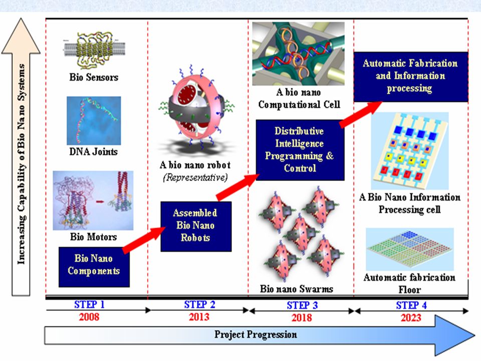
Design of bio-nanorobotics Application-medical, space and military DESIGN STEPS: Bio-nanocoponents: Development of bio-nano components from biological systems is the first step towards the design and development of an advanced bio-nanorobot, which could be used for future applications

31
ABc 5 Years from Now - Understanding of basic biological components and controlling their functions as robotic components. Examples are: (A) DNA which may be used in a variety of ways such as a structural element and a power source; (B) Hemagglutinin virus may be used as a motor; (C) Bacteriorhodopsin could be used as a sensor or a power source
 DNA which may be used in a variety of ways such as a structural element and a power source; (B) Hemagglutinin virus may be used as a motor; (C) Bacteriorhodopsin could be used as a sensor or a power source.")
32
Assembled Bio Nano Robots: A B (A) the bio-nano components will be used to fabricate complex bio robotic systems. A vision of a nano-organism: carbon nano-tubes form the main body; peptide limbs can be used for locomotion and object manipulation and the biomolecular motor located at the head can propel the device in various environments. (B) Modular Organization concept for the bio-nano robots. A single bio nano robot will have actuation, sensory and information processing capabilities.
 Modular Organization concept for the bio-nano robots. A single bio nano robot will have actuation, sensory and information processing capabilities..")
33
Distributive Intelligence, Programming and Control: A B (A) Basic bio nano robot forming a small swarm of five robots. The spatial arrangement of the individual bio nano robot will define the arrangement of the swarm. Also, these swarms could be re-programmed to form bindings with various other types of robots. The number of robots making a swarm will be dependent of the resulting capability required by the mission. Also the capability of attaching new robots at run time and replacing the non functional robots will be added. (B) A basic bio-nano computational cell. This will be based on one of the properties of the bio molecules, which is “reversibility”
 A basic bio-nano computational cell. This will be based on one of the properties of the bio molecules, which is reversibility .")
34
Automatic Fabrication and Information Processing Machines : 20 – 30 Years - An automatic fabrication floor layout. Different color represents different functions in automatic fabrication mechanisms. The arrows indicate the flow of components on the floor layout. Section 1 Basic stimuli storage – Control expression; Section 2 Bio molecular component manufacturing (actuator / sensor); Section 3 Linking of bio-nano components; Section 4 Fabrication of bio-nano robots (assemblage of linked bio-nano components).
; Section 3 Linking of bio-nano components; Section 4 Fabrication of bio-nano robots (assemblage of linked bio-nano components)..")
36
Design philosophy: Modular organisation-Modular organization defines the fundamental rule and hierarchy for constructing a bio-nanorobotic system. Such construction is performed through stable integration of the individual ‘bio- modules or components’, which constitute the bio-nanorobot Showing the bio nano code and the fractal modularity principle. The “||” symbol integrates the various bio-modules and collectively represents a higher order module or a bio-nano robot

37
5. COMPUTATIONAL ANALYSIS b. Mobile nanorobot interaction and tasks Perform molecular assembly manipulation Biomedical engineering applications c. Storage simulation data - Later analyses for nanodevices manufacturing Serves on sensing/actuation device design- Layout for DNA based new ICs: nanobioelectronics a. A 3D tool to simulate the nanorobot within the human body - Enable fast nanorobots control investigation - Provide physical parameters for manufacturing evaluation - Nanorobot Control Design (NCD) system
 system.")
38
Computational methods: Empirical force field methods: (Molecular mechanics):
:")
39
6. NANOROBOT DESIGN b. Nanorobot navigation:- Uses plane surfaces (three fins total) - Propulsion by bi-directional propellers: two simultaneously counter-rotating screw drives- navigational acoustic sensors a. For Molecular Manipulation nanorobot uses actuators nanorobot design
 - Propulsion by bi-directional propellers: two simultaneously counter-rotating screw drives- navigational acoustic sensors a. For Molecular Manipulation nanorobot uses actuators nanorobot design.")
40
7. SENSING METHODOLOGY a. Decision planning Medical target delivery Motion: random, chemical, thermochemical Behaviour activation

41
b. Physical parameters in the simulator Interactive simulation Blood Flow Signal Analysis (FEM) - velocity - temperature - shear stress - molecular concentrations 7. SENSING METHODOLOGY
 - velocity - temperature - shear stress - molecular concentrations 7. SENSING METHODOLOGY.")
42
8. CONTROL MODEL a. Nanorobots Collective Control Planning determines the kind of behaviour for r.ψ: y: surplus/deficit to the desired protein/drug amount. w: chemical level of the medical target i at time t. Q: total of protein captured by r in t. d: desired protein compound rate. x: substance amount injected in the medical target i.

43
8. CONTROL MODEL b. Signal Sensor - Based Control Reaction : molecules per second v: flow velocity D: diffusion coeficient C: molecules concentration per r: distance from the center of the vessel

44
9. VERIFICATION METHODOLOGIES - CASES STUDIES Nanorobots searching for malignant tissues a. Nanorobots for Cancer - Surgery / Drug Delivery / Early Diagnosis

45
Constant signal diffusion from injury target Genome Mapping - Chromosome 21 E-cadherin / bcl-2 gradient changed by tumour www.c a n b i o t e c h n e m s.com www.n a n o r o b o t d e s i g n.com

46
This high constant diffusion could be used as signals for robots. target area signal spreads further throughout vessel E-cadherin / bcl-2: protein signals to detect cancer Chemical & temperature signals activate nanorobots near target. www.c a n b i o t e c h n e m s.com www.n a n o r o b o t d e s i g n.com

47
20microns diameter vessel Comparative behaviors

48
Such control activation parameters could be used for biomedical applications – e.g. Coronary Atherosclerosis Blood temperature in the occluded region b. Nanorobots for Cardiology Blood Pressure Monitoring / Drug Delivery www.c a n b i o t e c h n e m s.com www.n a n o r o b o t d e s i g n.com

49
Nanorobots and Red Blood Cells Near the vessel occlusion sVCAM-1 chemical signal concentration in the stenosis www.c a n b i o t e c h n e m s.com www.n a n o r o b o t d e s i g n.com

50
c. Nanorobots for Diabetes - Glucose Monitoring patients must take small blood samples many times a day to control glucose levels. Such procedures are uncomfortable and extremely inconvenient Nanorobots with nanobiochemosensors (hSGLT3) can be used for pervasive diabetes monitoring.
 can be used for pervasive diabetes monitoring..")
51
11. CONCLUSION b. Rapid Evaluation of Various Control Algorithms First methodology for medical nanorobot investigation CONTRIBUTIONS First nanorobot architecture based on nanobielectronics a. Real-time digital simulation as a valuable tool for the better investigation of biomedical flow signals c. Show a practical approach to investigate nanodevices manufacturing for nanorobots e.g.: transducers/nanobiosensors prototyping

52
The Space Elevator a technology based on Nano Electro Mechanical System(NEMS)
")
53
Space Elevator Basics

54
The SE in Literature Artsutanov, Y. 1960. V Kosmos na Elektrovoze, Komsomolskaya Pravda, (contents described in Lvov 1967 Science 158:946). Isaacs, J.D., Vine, A.C., Bradner, H., and Bachus, G.E. 1966. Satellite Elongation into a true ‘Sky-Hook’. Science 151:682. Pearson, J. 1975. The Orbital tower: a spacecraft launcher using the Earth’s rotational energy. Acta Astronautica 2:785. Clarke, A.C. 1979. The Space Elevator: ‘Thought Experiment’, or Key to the Universe. Adv. Earth Oriented Appl. Science Techn. 1:39.
. Isaacs, J.D., Vine, A.C., Bradner, H., and Bachus, G.E Satellite Elongation into a true ‘Sky-Hook’. Science 151:682. Pearson, J The Orbital tower: a spacecraft launcher using the Earth’s rotational energy. Acta Astronautica 2:785. Clarke, A.C The Space Elevator: ‘Thought Experiment’, or Key to the Universe. Adv. Earth Oriented Appl. Science Techn. 1:39..")
55
From SciFi to NASA Capture an asteroid and bring into Earth orbit Mine the asteroid for carbon and extrude 10m diameter cable Asteroid becomes counterweight Maglev transport system Tall tower base Large system 300 years to never... From Smitherman, 1999

56
Initial Spacecraft Deployment spacecraft built with current technology Photovoltaic arrays receive power from Earth An MPD electric propulsion moves the spacecraft up to high Earth orbit Four 20-ton components are launched on conventional rockets and assembled

57
Proposed System: Overview First elevator: 20 ton capacity (13 ton payload) Constructed with existing or near-term technology Cost (US$10B) and schedule (15 years) Operating costs of US$250/kg to any Earth orbit, moon, Mars, Venus, Asteroids
 Constructed with existing or near-term technology Cost (US$10B) and schedule (15 years) Operating costs of US$250/kg to any Earth orbit, moon, Mars, Venus, Asteroids")
58
How Could It Be Done?

59
Carbon Nanotubes (CNTs) 5km continuous 1% CNT composite fiber Carbon nanotubes: measured at 200 GPa (54xKevlar) – Sufficient to build the elevator Mitsui(Japan): 120 ton/yr CNT production, US$100/kg – Sufficient to build the first elevator CNT composite fibers: 3-5% CNTs, 3 GPa, 5 km length – Not strong enough yet but a viable plan is in place to get there (Carbon Designs, Inc.)
 5km continuous 1% CNT composite fiber Carbon nanotubes: measured at 200 GPa (54xKevlar) – Sufficient to build the elevator Mitsui(Japan): 120 ton/yr CNT production, US$100/kg – Sufficient to build the first elevator CNT composite fibers: 3-5% CNTs, 3 GPa, 5 km length – Not strong enough yet but a viable plan is in place to get there (Carbon Designs, Inc.)")
60
Strain ) “Transverse” strain finds a natural release in a bond rotation of 90° for the armchair tube, thereby elongating the tube and releasing excess strain energy. Defect is formed, which leads to non-elastic behavior b) “Longitudinal” strain induces a 60° rotation in the zig-zag tube. Less tube elongation therefore more resistant to defect formation
 Longitudinal strain induces a 60° rotation in the zig-zag tube. Less tube elongation therefore more resistant to defect formation.")
61
Deployment Overview

62
The Components The Ribbon The Anchors The Climbers The Power

63
Ribbon Design The final ribbon is one- meter wide and composed of parallel high-strength fibers Interconnects maintain structure and allow the ribbon to survive small impacts Initial, low-strength ribbon segments have been built and tested

64
The Ribbon: Construction Initial production takes place on earth Aligned nanotubes are epoxyed into sheets, which are then combined (reinforced) Climbers have a similar system on- board to build tether
 Climbers have a similar system on- board to build tether")
65
Climbers Climbers built with current satellite technology Drive system built with DC electric motors Photovoltaic array (GaAs or Si) receives power from Earth 7-ton climbers carry 13- ton payloads Climbers ascend at 200 km/hr 8 day trip from Earth to geosynchronous altitude
 receives power from Earth 7-ton climbers carry 13- ton payloads Climbers ascend at 200 km/hr 8 day trip from Earth to geosynchronous altitude")
66
How to design the climber? Initial ~200 climbers used to build nano-ribbon Later used as launch vehicles for payloads from 20,000- 1,000,000 kg, at velocities up to 200km/hr

67
Power Beaming Power is sent to deployment spacecraft and climbers by laser Solid-state disk laser produces kWs of power and being developed for MWatts Mirror is the same design as conventional astronomical telescopes (Hobby-Eberly, Keck)
")
68
Anchor Anchor station is a mobile, ocean-going platform identical to ones used in oil drilling Anchor is located in eastern equatorial pacific, weather and mobility are primary factors

69
Challenges Induced Currents: milliwatts and not a problem Induced oscillations: 7 hour natural frequency couples poorly with moon and sun, active damping with anchor Radiation: carbon fiber composites good for 1000 years in Earth orbit (LDEF) Atomic oxygen: <25 micron Nickel coating between 60 and 800 km (LDEF) Environmental Impact: Ionosphere discharging not an issue Malfunctioning climbers: up to 3000 km reel in the cable, above 2600 km send up an empty climber to retrieve the first Lightning, wind, clouds: avoid through proper anchor location selection Meteors: ribbon design allows for 200 year probability-based life LEOs: active avoidance requires movement every 14 hours on average to avoid debris down to 1 cm Health hazards: under investigation but initial tests indicate minimal problem Damaged or severed ribbons: collatoral damage is minimal due to mass and distribution
 Atomic oxygen: <25 micron Nickel coating between 60 and 800 km (LDEF) Environmental Impact: Ionosphere discharging not an issue Malfunctioning climbers: up to 3000 km reel in the cable, above 2600 km send up an empty climber to retrieve the first Lightning, wind, clouds: avoid through proper anchor location selection Meteors: ribbon design allows for 200 year probability-based life LEOs: active avoidance requires movement every 14 hours on average to avoid debris down to 1 cm Health hazards: under investigation but initial tests indicate minimal problem Damaged or severed ribbons: collatoral damage is minimal due to mass and distribution")
70
Technical Budget ComponentCost Estimate (US$) Launch costs to GEO1.0B Ribbon production400M Spacecraft500M Climbers370M Power beaming stations 1.5B Anchor station600M Tracking facility 500M Other430M Contingency (30%)1.6B TOTAL ~6.9B Costs are based on operational systems or detailed engineering studies. Additional expenses will be incurred on legal and regulatory issues. Total construction should be around US$10B. Recommend construction of a second system for redundancy: US$3B

71
SE Operating Budget Annual Operating Budget per year in US$M Climbers0.2 - 2 each Tracking system10 Anchor station 10 Administration10 Anchor maintenance5 Laser maintenance20 Other30 TOTAL (50 launches)135 This is ~US$250/kg operating costs to any destination.
135 This is ~US$250/kg operating costs to any destination.")
72
Advantages Low operations costs - US$250/kg to LEO, GEO, Moon, Mars, Venus or the asteroid belts No payload envelope restrictions No launch vibrations Safe access to space - no explosive propellants or dangerous launch or re-entry forces Easily expandable to large systems or multiple systems Easily implemented at many solar system locations

73
Applications Solar power satellites - economical, clean power for use on Earth Solar System Exploration - colonization and full development of the moon, Mars and Earth orbit Telecommunications - enables extremely high performance systems

74
Global Attention Have briefed Congress, NASA HQ, NASA MSFC, AFRL, NSA, NRO, DARPA, FCC, FAA, and satellite insurance companies. Invited talks at Harvard/Smithsonian CfA, APL, GSFC, Berkeley, National Space Society, SPIE, Space and Robotics 2002, ISU, etc. Held the three Space Elevator Conferences. One session at Space and Robotics 2002, two sessions at the IAC meeting in Oct., 2004, and Space Exploration 2005 are focusing solely on our work. ESA, Japan, Canada and Australia have expressed interests in being involved. Reported positively in New York Times, Washington Post, Discover, Wired, Seattle Times, Space.com, Canadian National Post, Ad Astra, Science News, Maxim, Esquire, etc. Globally over 1000 media spots including live interviews on CNN, Fox News, and BBC.

75
Next Steps Material development efforts are underway by private industry Space elevator climber competition will demonstrate basic concept Engineering development centers in the U.S., Spain and Netherlands are under development Technical conferences continuing Greater public awareness Increased financial support being sought

76
The space elevator is a revolutionary Earth- to-space transportation system that will enable space exploration Design, deployment and operational scenarios for the first space elevator have been put together. Potential challenges have been laid out and solutions developed. Development of the space elevator requires an investment in materials and engineering but is achievable in the near future with a reasonable investment and development plan. Summary

Similar presentations


>")


492-8225 ECOT 250>")


 Spying on Cells -- Mechanisms of interacting molecular functions leading to new engineering designs of sensing events -- Nano sensors.>")


: List of parameters of condition: –Linear distance, angular displacement, vibration, displacement,>")


