Download presentation
Presentation is loading. Please wait.

1
Scale and Projections

2
Scale Scales are used to measure distances on technical drawings. Types of scales – Mechanical Engineers Scale (Fractional divisions) – Civil Engineer’s Scale (Division of 10) – Metric Scale – Architectural Scale (Fractional divisions) – Combination Scale
 – Civil Engineer’s Scale (Division of 10) – Metric Scale – Architectural Scale (Fractional divisions) – Combination Scale.")
3
Mechanical Engineer’s Scale Mechanical Drawings are drawn in inches. 16 Divisions per inch Scales – 1:1 Full Size – 1:2 Half Size – 1:4 Quarter Size – 1:8 One Eight Size

4
Civil Engineer’s Scale Civil Drawings are drawn in feet as the base unit. Scales commonly used – 1”:10’1”:100’ – 1”:20’1”:200’ – 1”:30’1”:300’ – 1”:40’1”:400’ – 1”:50’1”:500’ – 1”:60’1”:600’

5
Metric Scale Metric Mechanical Drawings are drawn in mm. Metric Civil Drawings are drawn in meters. Scale – 1:1 Full Size – 1:2 Half Size – 1:5 Fifth Size – 1:10 Tenth Size

6
Drawing Scale We use scale in drawing to represent objects in the appropriate size on our drawing sheet. – We can represent large objects on a B-Size sheet using scale. (1” = 50’) – We can represent small objects on B-Size Sheet using scale. (4:1) What are some examples that you might want to represent in a drawing?
 – We can represent small objects on B-Size Sheet using scale. (4:1) What are some examples that you might want to represent in a drawing .")
7
Drawing Scales are Ratios Drawing Size : Actual Size A rectangular box on a drawing with the scale of 2:1 has the measured dimensions 10” W x 16” L x 20” H. How large is the actual box?

8
Drawing Scales are Ratios Drawing Size : Actual Size You are looking at drawings for a proposed golf course. The distance from the tee-box to the hole is 12 inches. If the scale on the drawing is 1”:50’, how far is it from the tee-box to the hole.

9
Understanding Projections Behind every 2D drawing of an object is a space relationship involving the object and three “imagined” things: – The observer’s eye or station point – The plane of projection – The projectors Also called visual rays or lines of sight

10
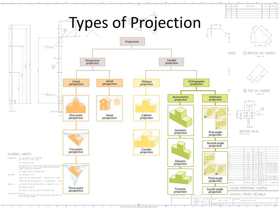
Types of Projection There are two main types of projection – Parallel projection – the projectors are parallel – Perspective projection – the projectors come together at the station point Perspective drawings represent objects as we see them

11
Types of Projection

13
Perspective Projection Perspective – The most realistic of the pictorial drawing styles because it is closest to the way that we see. – An ordinary photograph shows the view in perspective. We will not cover this view in this class. – You can study it on you own. See Chapter 16 in you text. – A drawing class would be another option.

14
Perspective Projection

15
Types of Parallel Projection Orthographic projections are a type of parallel projection – Orthographic (right angle) projections have parallel projectors that are perpendicular (90 degrees) to the plane of projection – In orthographic projection objects can be presented at true size or scaled at a proportion of their true size
 projections have parallel projectors that are perpendicular (90 degrees) to the plane of projection – In orthographic projection objects can be presented at true size or scaled at a proportion of their true size")
16
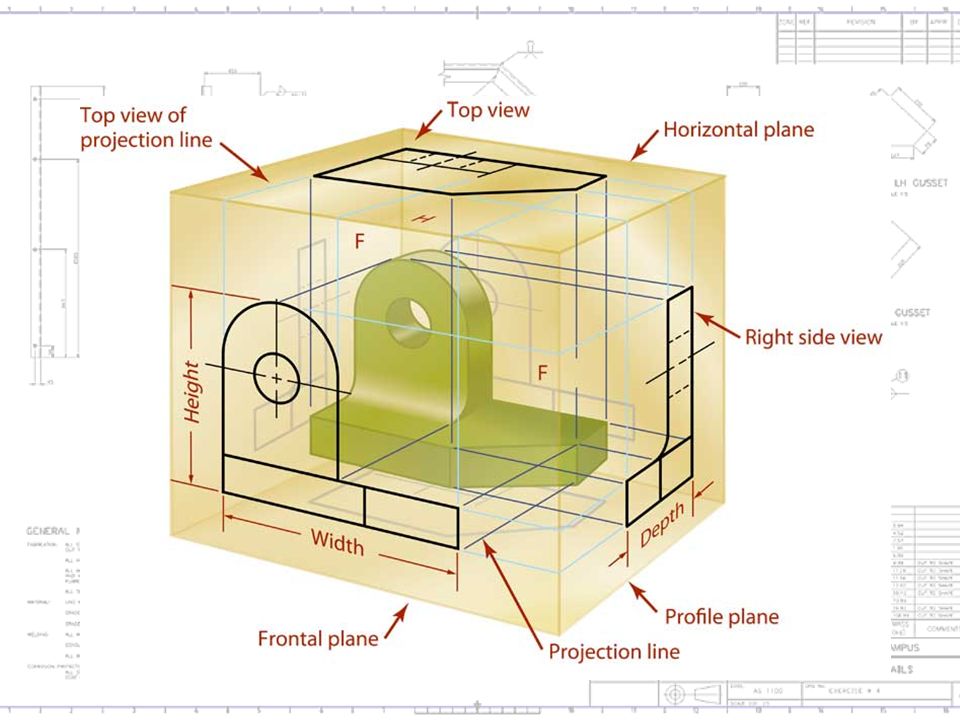
Types of Orthographic Projection Multiview projection – A two dimensional representation of a three dimensional object. – It shows one or more necessary views of an object Front, Rear, Top, Bottom, Right or Left

17
Multi-view drawing

19
Multiview Drawings First- and Third-Angle Projection There are two main systems used for projecting and unfolding the views: – Third-angle projection which is used in the United States, Canada and some other countries – First-angle projection which is primarily used in Europe and Asia You should understand both methods

20
Multiview Drawings Third-angle Projection US & Canada

21
Multiview Drawings First-angle Projection Europe & Asia

22
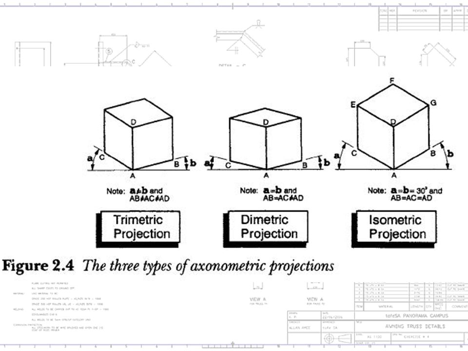
Types of Orthographic Projection Axonometric projections – Axonometric projection is a type of parallel projection used to create a pictorial drawing of an object, where the object is rotated along one or more of its axes relative to the plane of projection. – There are three main types of axonometric projection: isometric, dimetric, and trimetric projection.

23
Isometric Projection For a cube an isometric view obtained by first looking straight towards one face. Next the cube is rotated ±45° about the vertical axis, followed by a rotation of approximately ±35.264° about the horizontal axis

24
Isometric Projection In isometric projection, the most commonly used form of axonometric projection in engineering drawing, the direction of viewing is such that the three axes of space appear equally foreshortened, and there is a common angle of 60° between them. As the distortion caused by foreshortening is uniform the proportionality of all sides and lengths are preserved, and the axes share a common scale. This enables measurements to be read or taken directly from the drawing. Another advantage is that 60° angles are more easily constructed using only a compass and straightedge.

25
Foreshortening Foreshortening is the visual effect or optical illusion that causes an object or distance to appear shorter than it actually is because it is angled toward the viewer. Additionally, an object is often not scaled evenly: a circle often appears as an ellipse and a square can appear as a trapezoid. Two different projections of a stack of two cubes, illustrating oblique parallel projection foreshortening ("A") and perspective foreshortening ("B")
 and perspective foreshortening ( B ).")
26
Isometric Drawings

27
Isometric Grid - 30˚

28
Dimetric Projection In dimetric projection, the direction of viewing is such that two of the three axes of space appear equally foreshortened, of which the attendant scale and angles of presentation are determined according to the angle of viewing; the scale of the third direction (vertical) is determined separately.
 is determined separately.")
29
Trimetric Projection In trimetric projection, the direction of viewing is such that all of the three axes of space appear unequally foreshortened. The scale along each of the three axes and the angles among them are determined separately as dictated by the angle of viewing. Trimetric perspective is not used as often as the other two, and is found in only a few video games (Fallout,SimCity).
..")
31
Sim City 4 (2003) uses a trimetric projection.
 uses a trimetric projection.")
32
Fallout (1997) uses trimetric projection.
 uses trimetric projection.")
33
Other Types of Parallel Projection Oblique projection – when projectors are parallel to each other but are at an angle other than 90 degrees to the plane of projection Oblique projections are commonly drawn at a 45˚ angle from the plane of projection.

34
Oblique Projection

35
Pictorial Projections Reviewed

36
Types of Projection Technical drawings of 3D objects usually use one of four standard types of projection – Multiview – Axonometric – Oblique – Perspective Parallel ORTHOGRAPHIC PICTORIAL

Similar presentations
>")


