Download presentation
Presentation is loading. Please wait.

1
QRP POWER/SWR METER PROJECT – PART 1 Developed By Al Mecozzi WA8LBZ For Presentation At The February 16, 2011 Meeting Of The CRES Amateur Radio Club

2
WHERE DID THE IDEA FOR THIS PROJECT COME FROM? ● Some time ago, I got interested in Software Defined Radio (SDR). ● I purchased and built a Genesis Model 3020 All Mode, 30/20 M 5 Watt, SDR Transceiver kit. 5 Watt, SDR Transceiver kit. ● However, I did not have a meter to measure power and SWR in the 100 mW to 10 W range. 100 mW to 10 W range. ● Bill Erwin N9CX and I both have QRP SDR radios and had the same need for a meter to measure QRP power and SWR. need for a meter to measure QRP power and SWR. ● We looked at meters available to purchase off the shelf and meters available in kit form. available in kit form. ● For a number of reasons, cost, functionality, accuracy, etc., we decided to design and construct our own power and SWR meter. to design and construct our own power and SWR meter.
. ● I purchased and built a Genesis Model 3020 All Mode, 30/20 M 5 Watt, SDR Transceiver kit. 5 Watt, SDR Transceiver kit. ● However, I did not have a meter to measure power and SWR in the 100 mW to 10 W range. 100 mW to 10 W range. ● Bill Erwin N9CX and I both have QRP SDR radios and had the same need for a meter to measure QRP power and SWR. need for a meter to measure QRP power and SWR. ● We looked at meters available to purchase off the shelf and meters available in kit form. available in kit form. ● For a number of reasons, cost, functionality, accuracy, etc., we decided to design and construct our own power and SWR meter. to design and construct our own power and SWR meter..")
3
The development of the QRP Power/SWR Meter was shared by Al Mecozzi WA8LBZ and Bill Erwin N9CX. The program will be presented in two parts as follows: ● Part 1 – The SENSOR and DETECTOR Sections will be presented by Al. ● Part 2 - The PROGRAMMING and METERING Sections, and Printed Circuit Board (PCB) development will be presented by Bill. by Bill.
 development will be presented by Bill. by Bill..")
4
GOALS FOR THE QRP POWER/SWR METER Power Source: +12 VDC Power Source: +12 VDC RF Power Range: 100 mW to 10 W RF Power Range: 100 mW to 10 W Power Measurement Accuracy: Better than +/- 10% from 160 to 10 meters Power Measurement Accuracy: Better than +/- 10% from 160 to 10 meters Display: Digital readout Display: Digital readout Calibration: Internal control Calibration: Internal control Controls: Power switch Controls: Power switch Connectors: DC, XMTR and ANT Connectors: DC, XMTR and ANT Enclosure: Metal Enclosure: Metal

5
THE POWER/SWR METER HAS FOUR SECTIONS SENSOR DETECTOR PROGRAMM ING METERING

6
THE SENSOR What does the sensor do? What does the sensor do? It performs two basic functions: It performs two basic functions: 1. It provides a path for RF energy to move from the transmitter to 1. It provides a path for RF energy to move from the transmitter to the antenna. the antenna. 2. It samples the RF energy in both directions and passes it 2. It samples the RF energy in both directions and passes it to a detector. to a detector.

7
THE SENSOR I started by researching the various sensors I had seen in the pages I started by researching the various sensors I had seen in the pages of QST magazines throughout the years going as far back as 1959. of QST magazines throughout the years going as far back as 1959. Of all the sensors I researched, I selected the four most often used. Of all the sensors I researched, I selected the four most often used. Strip Line Bridge Wheatstone Bridge Bruene Bridge Stockton Bridge

8
Strip Line Bridge PROS: Easy to construct Inexpensive CONS: Poor sensitivity Overly frequency sensitive

9
This is what a strip line bridge looks like.

10
Wheatstone Bridge PROS: Easy to construct Easy to construct Inexpensive Inexpensive CONS: Resistance between Resistance between transmitter and antenna transmitter and antenna Limited power range Limited power range

11
Bruene Bridge PROS: No resistance between No resistance between transmitter and antenna transmitter and antenna High power range High power range CONS: Requires balancing Requires balancing Relatively expensive Relatively expensive

12
Stockton Bridge PROS: No balancing required No balancing required Power range can be controlled by Power range can be controlled by the turns ratio of the transformers the turns ratio of the transformersCONS: Two transformers to wind Two transformers to wind

13
It has a small parts count as compared to the other bridges. It has a small parts count as compared to the other bridges. It is relatively inexpensive. It is relatively inexpensive. It is easy to construct. It is easy to construct. It does not require balancing. It does not require balancing. Measurable power range can be controlled by the turns ratio Measurable power range can be controlled by the turns ratio of the transformers. of the transformers. It extracts about 1% of the RF power moving from the It extracts about 1% of the RF power moving from the transmitter to the antenna. transmitter to the antenna. I SELECTED THE STOCKTON BRIDGE FOR THE SENSOR FOR THE FOLLOWING REASONS:

14
Stockton Bridge Drawing Of A Bridge

15
This was our first prototype of a Stockton Bridge

16
Because it was readily available, inexpensive, and easy to construct, I selected this Stockton Bridge (Universal SWR Bridge Kit, $8.00) from Kits and Parts (http://www.kitsandparts.com/store2.php).
 from Kits and Parts (")
17
THE DETECTOR Again, going back in time, all of the sensors I saw used only one type of Again, going back in time, all of the sensors I saw used only one type of detector. detector. Voltage Peak Detector

18
Pros ● Small parts count ● Easy to construct ● Inexpensive Cons ● Poor accuracy at low power levels ● Limited power range because of diode characteristics characteristics

19
Voltage Peak Detector

20
Diode Voltage Peak Detectors Have Poor Accuracy At Low Power Levels? ● The diode voltage peak detector suffers from great inaccuracies at low power levels. at low power levels. ● This happens because the diode requires a small amount of voltage across it before it conducts current. voltage across it before it conducts current. ● At low power levels, the diode acts more like a resistor than a diode. diode. ● At very low input voltages, the error is great. ● How can this error be minimized?

21
One Solution Is To Use An Op Amp Circuit To Compensate For Diode Loses This circuit uses a matched diode to add the lost DC voltage on top voltage peak detectors output.

22
Compensation Amplifier Is Enclosed In Red

23
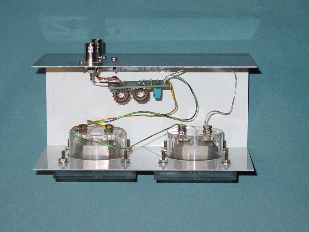
Here Are The SENSOR And DETECTOR Used In The QRP Power and SWR Meter

24
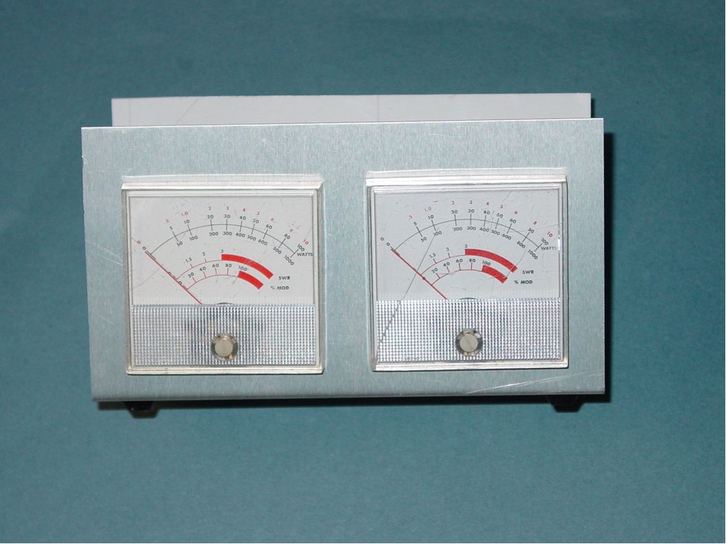
I BUILT TWO QRP POWER/SWR METERS ● One using analog meters ● One using a digital readout

27
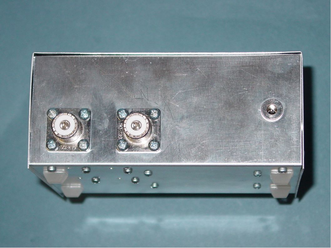
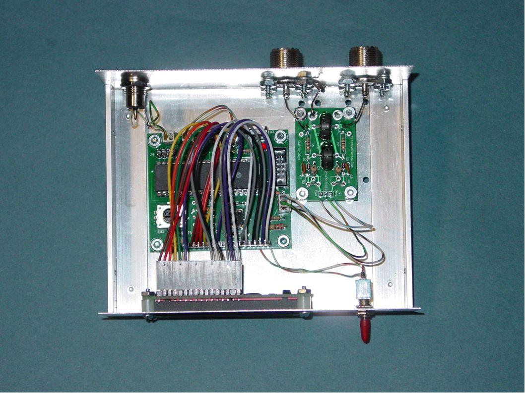
VIEWS OF THE WA8LBZ QRP POWER / SWR METER PROTOTYPE

31
ANY QUESTIONS? Now it is time for Bill's portion of the program

Similar presentations


The Basics.>")


 _ + v if (0-pk) _ + v if (DC) _ Consider an idealized, lossless detector, driven by an unmodulated.>")


