Download presentation
Presentation is loading. Please wait.

2
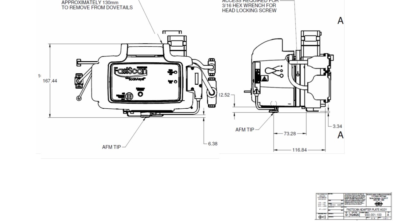
We do not have as much clearance as is shown here

3
15mm 20mm sample stage AFM stage Yale chip, at center must be no more than 2.5mm thick. The dimension shown at right, stage to AFM tip, is ~2.75mm in fully raised position. Chip 1-2mm thick is preferable 20mm AFM stage 30mm right side interference zone left side, NO interference FRONT VIEW # Large chip only, no platform alternative We will have trouble attaching wires to pads much smaller than 1mm.

4
sample stage AFM stage 20mm 10mm 15mm 20mm AFM stage red circle is the imaging window – ebeam wires must be under this window green is core chip with ebeam wires and small access pads Purple is the platform on which the ebeam chip is glued and is the surface for larger contact/bonding pads to be used for attachment of large wires here at Marshall As alternative, these final wires could come out side instead of front, if sides will be used, your ~1x1mm shadowmask pads must be placed outside the 30mm side interference zone above – left side as seen here is more open 30mm right side interference zone More access over here on left side left side, NO interference TOP VIEW FRONT VIEW Small chip with platform alternative Yale chip plus platform at center must be no more than 2.5mm thick. The dimension shown at right, stage to AFM tip, is ~2.75mm in fully raised position. Chip plus platform combined 1-2mm thick is preferable

5
sample stage AFM stage Yale chip plus platform at center must be no more than 2.5mm thick. The dimension shown at right, stage to AFM tip, is ~2.75mm in fully raised position. Chip plus platform combined 1-2mm thick is preferable FRONT VIEW 1-2mm By Shari Y. ~2014 FRONT VIEW cutaway

Similar presentations


>")


: Three independent vertical planes with 15 cm plastic shield in front, all planes.>")


 2010 National Fluid Power Association.>")

