Download presentation
Presentation is loading. Please wait.

1
Raspberry pi GPIO Basic’s Lecturer: Reza Arjmandi Summer 2016 Preface: This chapter contains some basic recipes for setting up and using the Raspberry Pi’s general-purpose input/output (GPIO) connector.
 connector.")
2
Raspberry pi Peripheral Circuits

3
GPIO Schematic There have actually been three versions of the Raspberry Pi GPIO connector. Two 26pin layouts for the original Raspberry Pi and one 40-pin layout that came in with the Raspberry Pi “+” models. Following Figure shows the GPIO pinout for both revisions 1 and 2 of the Raspberry Pi Model B

4
GPIO Schematic

5
At the top of the connector, there are 3.3V and 5V power supplies. The GPIO uses 3.3V for all inputs and outputs. Any pin with a number next to it can act as a GPIO pin. Those that have another name after them also have some other special purpose, so 14 TXD and 15 RXD are the transmit and receive pins of the serial interface. SDA and SCL form the I2C interface, and MOSI, MISO, and SCKL from the SPI interface. A GPIO pin can be used as either a digital input or a digital output, and both operate at 3.3V. Unlike the Arduino, the Raspberry Pi does not have any analog inputs. For that you must use an external analog-to-digital converter (ADC) or connect the Pi to an interface board (like the Gertboard) or to an Arduino or an aLaMode board, as discussed in future
 or connect the Pi to an interface board (like the Gertboard) or to an Arduino or an aLaMode board, as discussed in future.")
6
Keeping Your Raspberry Pi Safe when Using the GPIO Connector Obey these simple rules to reduce the risk of damaging your Raspberry Pi when using the GPIO connector: 1.Do not put more than 3.3V on any GPIO pin. 2.Do not draw more than 3mA per output. You can get away with drawing more, but this may shorten the life of the Pi. 3mA is enough to light a red LED with a 470Ω series resistor. 3.Do not poke at the GPIO connector with a screwdriver or any metal object when the Pi is powered up. 4.Do not power the Pi with more than 5V. 5.Do not draw more than a total of 50mA from the 3.3V supply pins. 6.Do not draw more than a total of 250mA from the 5V supply pins.

7
RPI.GPIO Library For use GPIO pins you should add RPi.GPIO in your code: import RPi.GPIO For using functions: RPi.GPIO.setmode(18,GPIO.OUT) OR import RPi.GPIO as GPIO For using functions: GPIO.setmode(18,GPIO.OUT)
 OR import RPi.GPIO as GPIO For using functions: GPIO.setmode(18,GPIO.OUT)")
8
Setting up numbering system for RPi.GPIO In RPi.GPIO you can use either pin numbers (BOARD) or the Broadcom GPIO numbers (BCM), but you can only use one system in each program. Use setmode() function: # for GPIO numbering, choose BCM GPIO.setmode(GPIO.BCM) # or, for pin numbering, choose BOARD GPIO.setmode(GPIO.BOARD)
 function: # for GPIO numbering, choose BCM GPIO.setmode(GPIO.BCM) # or, for pin numbering, choose BOARD GPIO.setmode(GPIO.BOARD).")
9
Setting up direction for RPi.GPIO A GPIO pin can be used as either a digital input or a digital output Use setup() function: # for Output: GPIO.setup(18, GPIO.OUT) # for Input: GPIO.setup(18, GPIO.IN)
 function: # for Output: GPIO.setup(18, GPIO.OUT) # for Input: GPIO.setup(18, GPIO.IN)")
10
Setting up direction for RPi.GPIO #enable pull up resistor: GPIO.setup(18, GPIO.IN, pull_up_down=GPIO.PUD_UP) #enable pull down resistor: GPIO.setup(18, GPIO.IN, pull_up_down=GPIO.PUD_DOWN) Each GPIO pin has software configurable pull-up and pull-down resistors. When using a GPIO pin as an input, you can configure these resistors so that one or either or neither of the resistors is enabled, using the optional pull_up_down parameter to GPIO.setup. If this parameter is omitted, then neither resistor will be enabled. This leaves the input floating, which means that its value cannot be relied upon and it will drift between high and low depending on what it picks up in the way of electrical noise.

11
Produce Output If a pin configure as output use output function: # for Output: GPIO.setup(18, GPIO.OUT) #or GPIO.setup(18, GPIO.OUT,initial=1) #Then, to switch the port/pin to 3.3V (equals 1/GPIO.HIGH/True)… GPIO.output(18, 1) #Or, to switch the port/pin to 0V (equals 0/GPIO.LOW/False)… GPIO.output(18, 0)
 #or GPIO.setup(18, GPIO.OUT,initial=1) #Then, to switch the port/pin to 3.3V (equals 1/GPIO.HIGH/True)… GPIO.output(18, 1) #Or, to switch the port/pin to 0V (equals 0/GPIO.LOW/False)… GPIO.output(18, 0)")
12
Reading Input If a pin configure as input use input function: # for Input: GPIO.setup(18, GPIO.IN, pull_up_down=GPIO.PUD_UP) #Then, for reading input: if(GPIO.input(18)==0): print(“key is pressed”)
 #Then, for reading input: if(GPIO.input(18)==0): print( key is pressed )")
13
Connecting an LED Connect an LED to one of the GPIO pins using a 470Ω or 1kΩ series resistor to limit the current.

14
Connecting an LED superuser Start a Python console from the Terminal with superuser access and enter these commands: import RPi.GPIO as GPIO import time GPIO.setmode(GPIO.BCM) GPIO.setup(18, GPIO.OUT) while (True): GPIO.output(18, True) time.sleep(0.5) GPIO.output(18, False) time.sleep(0.5)
 GPIO.setup(18, GPIO.OUT) while (True): GPIO.output(18, True) time.sleep(0.5) GPIO.output(18, False) time.sleep(0.5)")
15
Connecting a Push Switch

16
import RPi.GPIO as GPIO import time GPIO.setmode(GPIO.BCM) GPIO.setup(18, GPIO.IN, pull_up_down=GPIO.PUD_UP) while True: if GPIO.input(18) == False: print('Button Pressed') time.sleep(0.2)
 GPIO.setup(18, GPIO.IN, pull_up_down=GPIO.PUD_UP) while True: if GPIO.input(18) == False: print( Button Pressed ) time.sleep(0.2)")
17
Connecting a Push Switch You will need to run the program as superuser: pi@raspberrypi ~ $ sudo python switch.py You will notice that the switch is wired so that when it is pressed, it will connect pin 18 configured as an input to GND. The input pin is normally pulled up to 3.3V by the optional argument pull_up_down=GPIO.PUD_UP in GPIO.setup. This means that when you read the input value using GPIO.input, False will be returned if the button is pressed.

18
Connecting a Push Switch You might expect the push switch to have just two connections, which are either open or closed. While some of these tactile push switches do have just two connections, most have four. Following Figure shows how these connections are arranged. Actually, there are only really two electrical connections, because inside the switch package pins B and C are connected together, as are A and D.

19
Switching a High-Power DC Device Using a Transistor These high-power LEDs use far too much current to light directly from a GPIO pin. They also require 12V rather than the 3.3V. To control such a high-power load, you need to use a transistor.

20
Switching a High-Power DC Device Using a Transistor the positive supply is connected directly to the positive side of the LED panel, and the negative side of the LED panel is connected to the drain of the MOSFET. The source connection of the MOSFET is connected to GND, and the MOSFET’s gate pin controls the flow of current from the drain to the source. If gate voltage is above about 2V, the MOSFET will turn on and current flows through both it and the LED module.

21
Switching a High-Power Device Using a Relay Use a relay and small transistor. relays are slow mechanical devices, so don’t try to use them with PWM. It may damage the relay. Relays have been around since the early days of electronics and have the great advantage of being easy to use, plus they’ll work in any situation where a switch would normally work—for example, when you’re switching AC (alternating current) or in situations where the exact wiring of the device being switched is unknown.
 or in situations where the exact wiring of the device being switched is unknown..")
22
Switching a High-Power Device Using a Relay

23
A relay is essentially a switch whose contacts are closed when an electromagnet pulls them together. Since the electromagnet and switch are not connected electrically in any way, this protects the circuit driving the relay coil from any high voltages on the switch side. The downside of relays is that they are slow to operate and will eventually wear out after many hundreds of thousands of operations. This means they are only suitable for slow on/off control, not for fast switching like PWM. The coil of a relay requires about 50 mA to close the connections. Because a Raspberry Pi GPIO pin is only capable of supplying about 3 mA, you need to use a small transistor as a switch The base (middle lead) is connected to the GPIO pin via a 1kΩ resistor to limit the current. The emitter is connected to GND, and the collector to one side of the relay. The other side of the relay is connected to 5V on the GPIO connector. The diode is used to suppress any highvoltage pulses that occur when the transistor rapidly switches the power to the relay’s coil.
 is connected to the GPIO pin via a 1kΩ resistor to limit the current. The emitter is connected to GND, and the collector to one side of the relay. The other side of the relay is connected to 5V on the GPIO connector. The diode is used to suppress any highvoltage pulses that occur when the transistor rapidly switches the power to the relay’s coil..")
24
Controlling High-Voltage AC Devices PowerSwitch Tail II Use a PowerSwitch Tail II PowerSwitch Tail The PowerSwitch Tail uses a relay, but to switch the relay, it uses a component called an opto-isolator that has an LED shining onto a photo-TRIAC (a high-voltage, lightsensitive switch); when the LED is illuminated, the photo-TRIAC conducts, supplying current to the relay coil.
; when the LED is illuminated, the photo-TRIAC conducts, supplying current to the relay coil.")
25
Making a User Interface to Turn Things On and Off You want to make an application to run on the Raspberry Pi that has a button for turning things on and off. Tkinter checkbutton Using the Tkinter library user interface framework, write a Python program that uses a checkbutton to turn the GPIO pin on and off (following figure)
.")
26
Making a User Interface to Turn Things On and Off from Tkinter import * import RPi.GPIO as GPIO import time GPIO.setmode(GPIO.BCM) GPIO.setup(18, GPIO.OUT) class App: def __init__(self, master): frame = Frame(master) frame.pack() self.check_var = BooleanVar() check = Checkbutton(frame, text='Pin 18', command=self.update,variable=self.check_var, onvalue=True, offvalue=False) check.grid(row=1) def update(self): GPIO.output(18, self.check_var.get()) root = Tk() root.wm_title('On / Off Switch') app = App(root) root.geometry("200x50+0+0") root.mainloop()
 GPIO.setup(18, GPIO.OUT) class App: def __init__(self, master): frame = Frame(master) frame.pack() self.check_var = BooleanVar() check = Checkbutton(frame, text= Pin 18 , command=self.update,variable=self.check_var, onvalue=True, offvalue=False) check.grid(row=1) def update(self): GPIO.output(18, self.check_var.get()) root = Tk() root.wm_title( On / Off Switch ) app = App(root) root.geometry( 200x ) root.mainloop()")
27
Making a User Interface to Turn Things On and Off In Python 3, the Tkinter library has been renamed tkinter with a lowercase t. superuser Note that you will need to run it with sudo because the RPi.GPIO requires you to have superuser privileges to access the GPIO hardware The example program defines a class called App that contains most of the application code. Its initializer function creates a member variable called check_var that contains an instance of BooleanVar that is then supplied as the variable option to the checkbutton. This ensures that every time the checkbutton is clicked, the value in this variable will be changed. The command option runs the update command every time such a change occurs. The update function simply writes the value in check_var to the GPIO output.

28
Using a Breadboard with Jumper Leads

29
Using a Breadboard with a Pi Cobbler

30
Getting Started with a PiFace Digital Interface Board

31
Getting Started with a Gertboard

32
Getting Started with a RaspiRobot Board

33
Using a Humble Pi Prototyping Board

34
Using a Pi Plate Prototyping Board

35
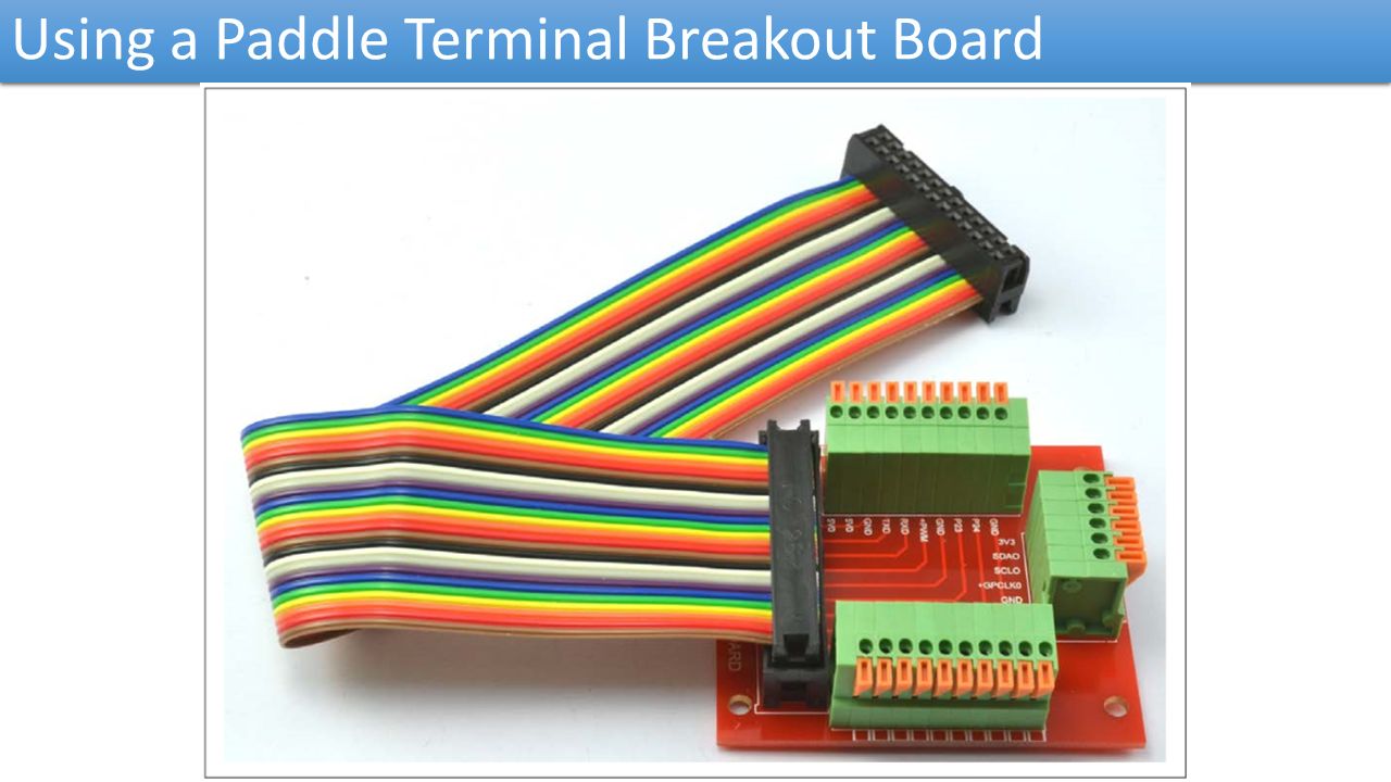
Using a Paddle Terminal Breakout Board

37
Contact us www.e-system.ir Info@e-system.ir

Similar presentations


 Thursday See ScheduleSchedule SE-2811 Slide design:>")

>")


