Download presentation
Presentation is loading. Please wait.

1
Circuit Calculations

2
SERIES CIRCUITS

3
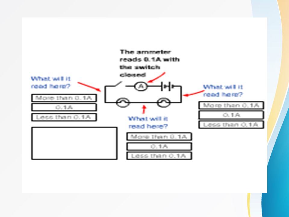
BASIC RULES A series circuit has certain characteristics and basic rules : 1. The same current flows through each part of a series circuit. 2. The total resistance of a series circuit is equal to the sum of individual resistances. 3. Voltage applied to a series circuit is equal to the sum of the individual voltage drops. 4. If the circuit is broken at any point, no current will flow. Let's look at each of these rules closer to gain an understanding of series circuits.

4
"1. The same current flows through each part of a series circuit." In a series circuit, the amperage at any point in the circuit is the same. This will help in calculating circuit values using Ohm's Law. You will notice from the diagram that 1 amp continually flows through the circuit. We will get to the calculations in a moment.

6
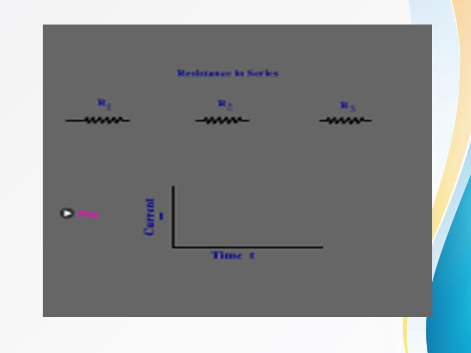
"2. The total resistance of a series circuit is equal to the sum of individual resistances." In a series circuit you will need to calculate the total resistance of the circuit in order to figure out the amperage. This is done by adding up the individual values of each component in series. In this example we have three resistors. To calculate the total resistance we use the formula: R T = R 1 + R 2 + R 3 5 + 5 + 10 = 20 Ohms R total is 20 Ohms

7
"Voltage Drops" Before we go any further let's define what a "voltage drop" is. A voltage drop is the amount the voltage lowers when crossing a component from the negative side to the positive side in a series circuit. If you placed a multimeter across a resistor, the voltage drop would be the amount of voltage you are reading. This is pictured with the red arrow in the diagram.

8
"3. Voltage applied to a series circuit is equal to the sum of the individual voltage drops." This simply means that the voltage drops have to add up to the voltage coming from the battery or batteries. V total = V 1 + V 2 + V 3... In our example above, this means that 5V + 5V = 10V.

9
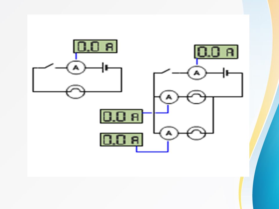
“4. If the circuit is broken at any point, no current will flow." The best way to illustrate this is with a string of light bulbs. If one is burnt out, the whole thing stops working.

11
PARALLEL CIRCUITS

12
A Parallel circuit is one with several different paths for the electricity to travel. It's a river that has been divided up into smaller streams. However, all the streams come back to the same point to form the river once again. See figure 1. The parallel circuit has extremely different characteristics than a series circuit. For one, the total resistance of a Parallel Circuit is NOT equal to the sum of the resistors (like in a series circuit). The total resistance in a parallel circuit is always less than any of the branch resistances. Adding more parallel resistances to the paths causes the total resistance in the circuit to decrease. As you add more and more branches to the circuit the total current will increase
. The total resistance in a parallel circuit is always less than any of the branch resistances. Adding more parallel resistances to the paths causes the total resistance in the circuit to decrease. As you add more and more branches to the circuit the total current will increase.")
13
BASIC RULES A Parallel circuit has certain characteristics and basic rules : 1. A parallel circuit has two or more paths for current to flow. 2. Voltage is the same across each component of the parallel circuit. 3. The sum of the currents through each path is equal to the total current that flows from the source. 4. You can find total resistance in a Parallel circuit with the following formula: 1/R t = 1/R 1 + 1/R 2 + 1/R 3 +...( R t = R (t)otal ) 5. If one of the parallel paths is broken, current will continue to flow in all the other paths.
otal ) 5. If one of the parallel paths is broken, current will continue to flow in all the other paths..")
14
"1. A parallel circuit has two or more paths for current to flow through." This is self explanatory. Simply remember that PARALLEL means two paths up to thousands of paths. The flow of electricity is divided between each according to the resistance along each route.

16
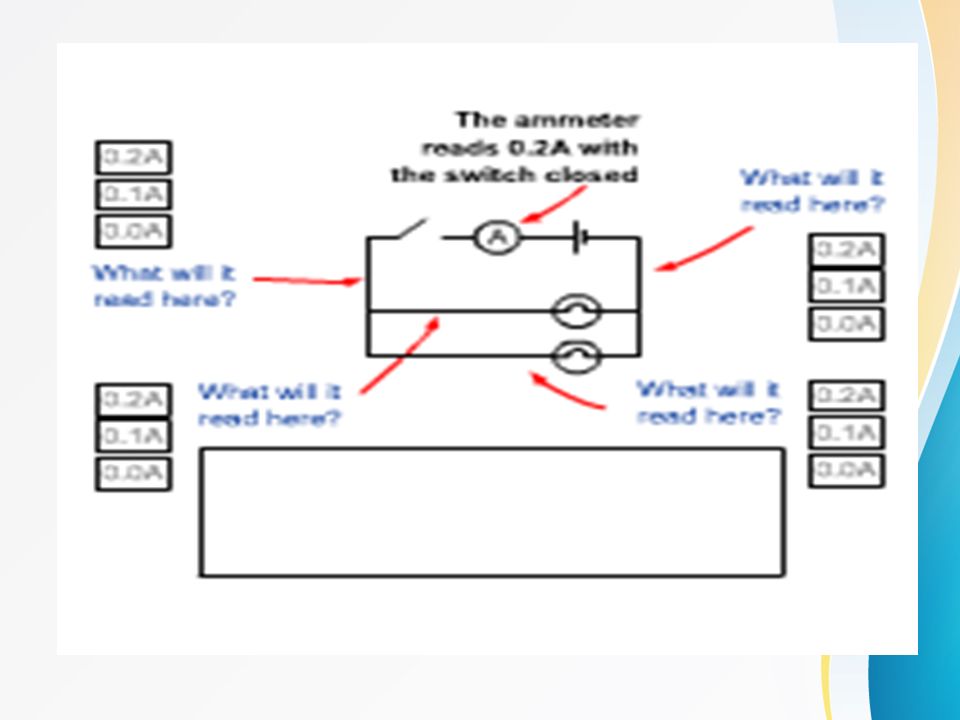
"2. Voltage is the same across each component of the parallel circuit." You may remember from the last section that the voltage drops across a resistor in series. Not so with a parallel circuit. The voltage will be the same anywhere in the circuit.

17
"3. The sum of the currents through each path is equal to the total current that flows from the source." If one path is drawing 1 amp and the other is drawing 1 amp then the total is 2 amps at the source. Simply remember for now that the branch currents must add up to equal the source current.

20
"4. You can find TOTAL RESISTANCE in a Parallel circuit with the following formula: 1/R t = 1/R 1 + 1/R 2 + 1/R 3 +... Before we get into the calculations, keep in mind what we said at the start of this section: "The total resistance of a parallel circuit is NOT equal to the sum of the resistors (like in a series circuit). That said, let's dig into the formula.
. That said, let s dig into the formula..")
21
We will use a parallel circuit with 3 paths as an example (it can just as easily be 2, 4 or a 1000 resistors in parallel). The power source is providing 10 volts and the value of the resistors are 4 Ohm, 4 Ohm and 2 Ohm. Let's surmise this EXAMPLE for clarity: Voltage = 10V R 1 = 4 Ohm R 2 = 4 Ohm R 3 = 2 Ohm Remember that "R t " means Total resistance of the circuit. R 1, R 2, etc. are Resistor one, Resistor two, etc.

22
Now we will apply the formula above to this example: 1 1 1 1 -- = -- + -- + -- Rt R1 R2 R3 Therefore: 1 1 1 1 -- = -- + -- + -- Rt 4 4 2 It is easiest to change the fractions into decimal numbers (example 1 divide by 4 equals.25): 1/Rt =.25 +.25 +.5 1/Rt = 1 Now you have to get rid of the 1 on the left side so. Rt = 1/1 Rt = 1 Ohm

23
NOW, Let's try a more complex one: Voltage = 120 Volts R1 = 100 Ohms R2 = 200 Ohms R3 = 1000 Ohms R4 = 1 Ohms 1/Rt = 1/100 + 1/200 + 1/1000 + 1/1 1/Rt =.01 +.005 +.001 + 1 1/Rt = 1.016 Rt = 1/1.016 =.98 Ohms

24
"5. If one of the parallel paths is broken, current will continue to flow in all the other paths." The best way to illustrate this is also with a string of light bulbs in parallel. If one is burnt out, the others stay lit.

26
COMBINATION CIRCUITS

27
"COMBINATION CIRCUIT" is (as you may have already guessed) a circuit that is a blend of series paths and parallel paths. Most circuits are of this variety. Don't be afraid to tackle these circuits as far as the math goes. You merely have to break each part of the circuit down into either a series circuit or parallel circuit. Here's how this is done:

28
You must first figure out the resistance of each individual parallel path in the circuit. Let's take the circuit to the left as an example. There is an 8 Ohm resistor in series (R 1 ) and two 4 Ohm resistors in parallel, R 2 ||R 3 (Note: The || means that the two resistors are in parallel). To figure out the total resistance of that section of the circuit we must calculate the parallel resistance first: 1/R = 1/R 2 + 1/R 3 1/R = 1/4 + 1/4 1/R =.25 +.25 1/R =.5 R = 1/.5 = 2 Ohms
 and two 4 Ohm resistors in parallel, R 2 ||R 3 (Note: The || means that the two resistors are in parallel). To figure out the total resistance of that section of the circuit we must calculate the parallel resistance first: 1/R = 1/R 2 + 1/R 3 1/R = 1/4 + 1/4 1/R = /R =.5 R = 1/.5 = 2 Ohms.")
29
Now that you know the resistance of the parallel 'subcircuit', you can add all the series resistances. Find the total resistance in the circuit by adding R 1 and R 2 ||R 3. R t = R 1 + (R 2 ||R 3 ) R t = 8 Ohms + 2 Ohms R total = 10 Ohms
 R t = 8 Ohms + 2 Ohms R total = 10 Ohms.")
30
The Resistor

31
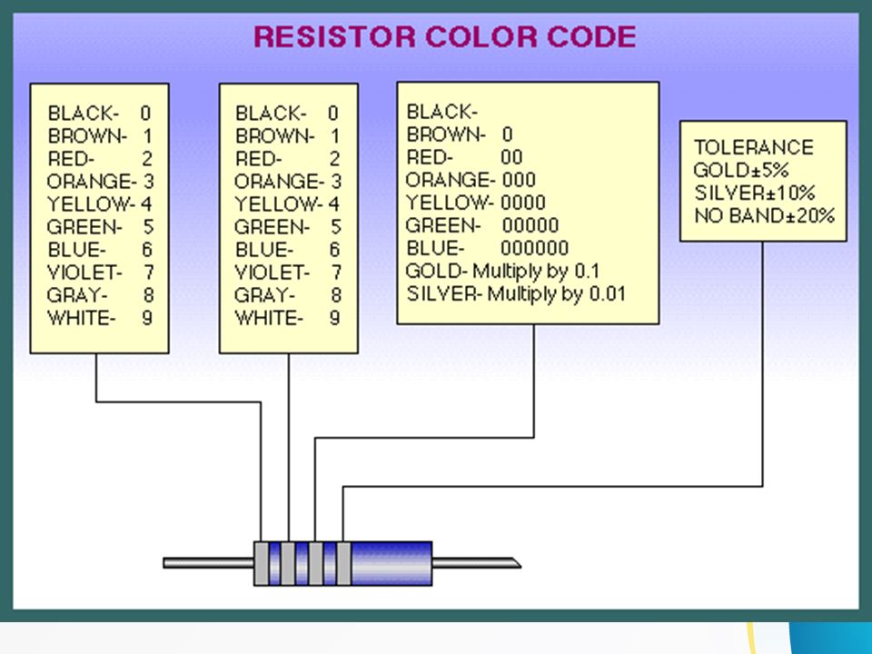
Resistors are components that resist the flow of electrical current. The higher the value of resistance (measured in ohms) the lower the current will be. Resistors are colour coded. To read the colour code of a common 4 band 1K ohm resistor with a 5% tolerance, start at the opposite side of the GOLD tolerance band and read from left to right. Write down the corresponding number from the colour chart below for the 1st colour band (BROWN). To the right of that number, write the corresponding number for the 2nd band (BLACK). Now multiply that number (you should have 10) by the corresponding multiplier number of the 3rd band (RED)(100). Your answer will be 1000 or 1K. It's that easy.
 the lower the current will be. Resistors are colour coded. To read the colour code of a common 4 band 1K ohm resistor with a 5% tolerance, start at the opposite side of the GOLD tolerance band and read from left to right. Write down the corresponding number from the colour chart below for the 1st colour band (BROWN). To the right of that number, write the corresponding number for the 2nd band (BLACK). Now multiply that number (you should have 10) by the corresponding multiplier number of the 3rd band (RED)(100). Your answer will be 1000 or 1K. It s that easy..")
34
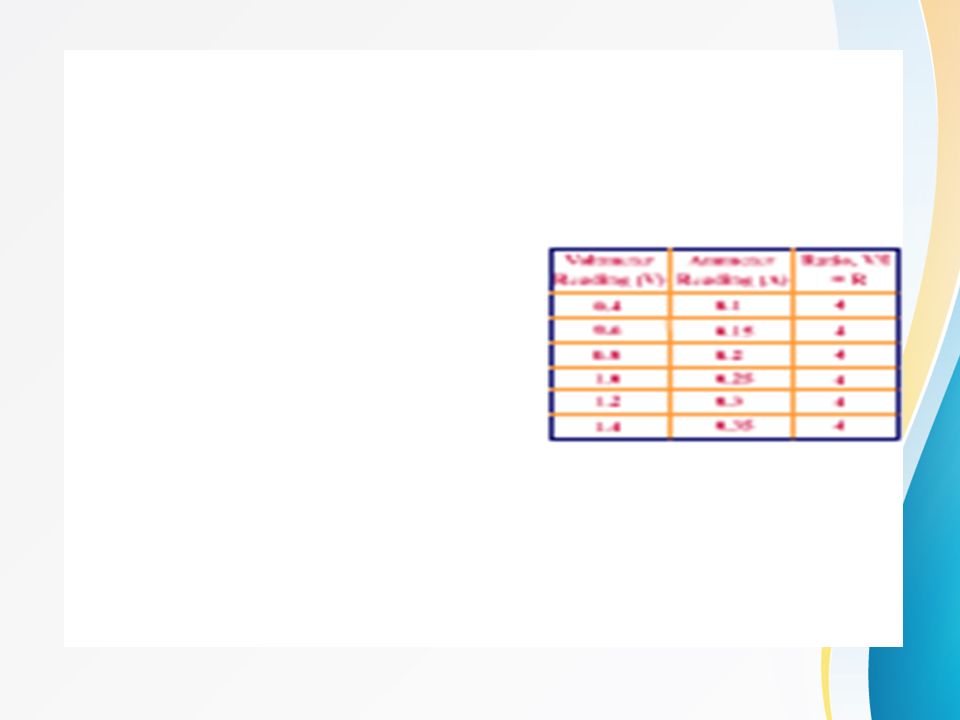
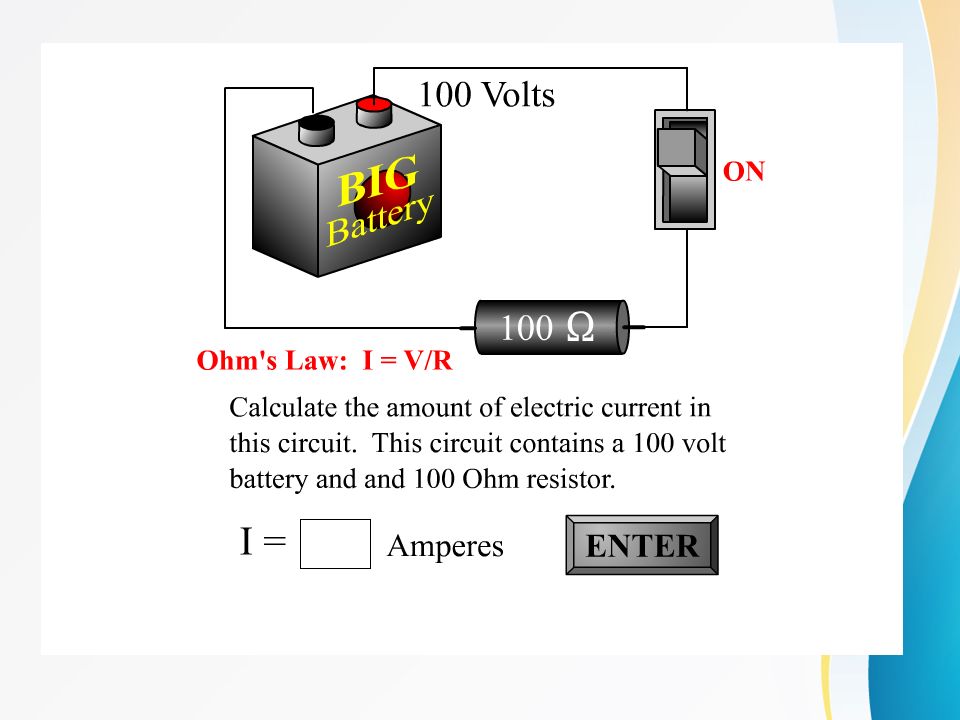
Resistance can be used to control current. Current can be controlled by the Voltage. These three variables must be linked somehow. Ohm’s Law

36
Complete the table in your worksheets

Similar presentations


 If current is disrupted through one element (e.g. the light goes out) then they.>")


 Kendriya Vidyalaya,Golaghat.>")


