Download presentation
Presentation is loading. Please wait.

1
Teknologi dan Rekayasa Ventilation and Air Distribution

2
Fundamentals of Residential IAQ Infiltration Natural Ventilation Mechanical Ventilation Source Control Dilution Ventilation Local Exhaust Pressurization/Depressurization and Climate

3
Infiltration Uncontrolled inward leakage of air through cracks and interstices. Generally caused by wind and stack effects. 50 CFM In Passively 50 CFM Out Passively

4
Natural Ventilation Ventilation occurring as a result of only natural forces through intentional openings such as doors and windows.

5
Mechanical Ventilation The active process of supplying air to or removing air from an indoor space by powered equipment such as fans and blowers. Does not include non-powered ventilation devices.

6
Source Control The concept of limiting the sources of indoor air pollution by limiting the amount of polluting materials and capturing the pollutants at the source.

7
Dilution Ventilation The concept of bringing in enough outdoor “good” or “fresh” air to dilute whatever pollutants are in the house. Depends on the quality of the outdoor air and the strength of the pollutant.

8
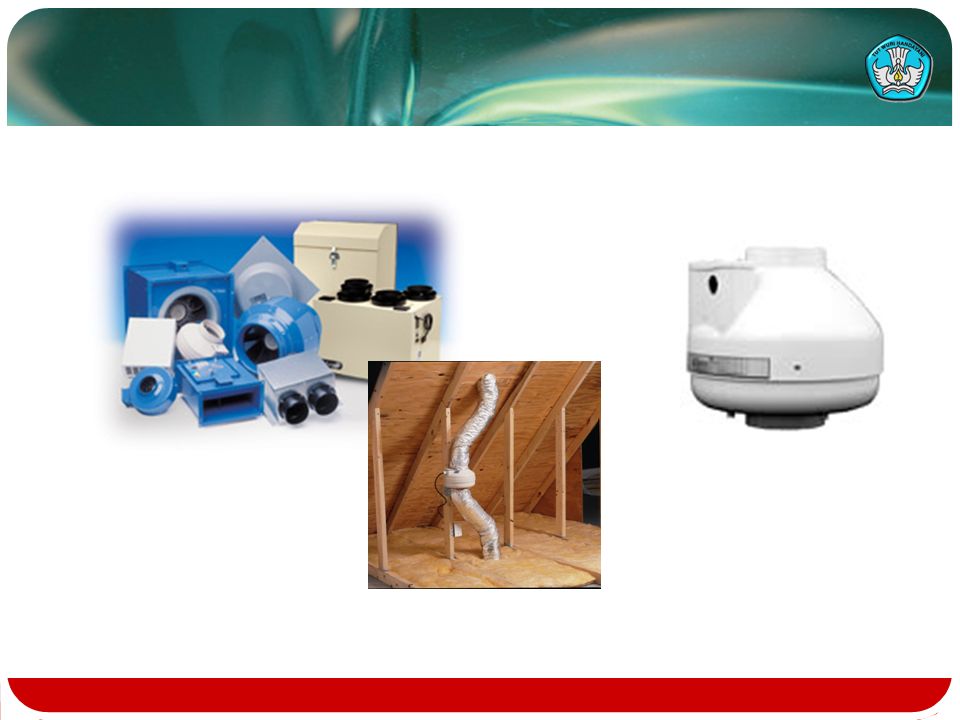
Local Exhaust The concept of exhausting air to capture the pollutant(s) at the source. Examples include bath or utility room exhaust and kitchen exhaust. May be accomplished with dedicated fans in the ceiling or wall or remote fans ducted from the grille to the fan. Remote fans may have a single pickup or be multiport fans that exhaust from several locations.

9
Local Exhaust Fantech Aupu Monodraught Tamarack

10
Pressurization/Depressurization Issues and Local Climate Ventilation systems must be selected to reduce the potential for causing problems in the building due to pressurization or depressurization. This is a function of the local climate conditions, the ventilation system, the heating system, and the building shell components.

11
Pressurization/Depressurization Issues and Local Climate (cont) In general, condensation and the potential for mold can be reduced by: Avoiding positive pressurization of the building in cold climates. Avoiding depressurization of the building in hot, humid climates. Temperate climates can tolerate a higher level of differential pressure.

12
Pressurization/Depressurization Issues and Local Climate (cont) In cold climates, supply ventilation systems can provide too much air and therefore too much pressurization of the building, driving moisture-laden household air into the building envelope where the moisture can condense on the cold surfaces.
 In cold climates, supply ventilation systems can provide too much air and therefore too much pressurization of the building, driving moisture-laden household air into the building envelope where the moisture can condense on the cold surfaces.")
13
Pressurization/Depressurization Issues and Local Climate (cont) In hot, humid climates with air conditioning, too much exhaust ventilation can pull air into the wall assembly where it can condense on the back side of the drywall, causing mold and deterioration of the building materials.
 In hot, humid climates with air conditioning, too much exhaust ventilation can pull air into the wall assembly where it can condense on the back side of the drywall, causing mold and deterioration of the building materials.")
14
Pressurization/Depressurization Issues and Local Climate (cont) Too much depressurization by large mechanical exhaust devices can reverse the flow in chimneys. This can cause backdrafting or spillage of combustion gases from naturally vented appliances, even when the device fires.

15
What’s too much pressurization/depressurization and what are the causes?

16
7 Day Depressurization & CO Observations (Grimsrud & Hadlick, 1995)
")
17
Depressurization from Exhaust Equipment (Grimsrud and Hadlich, 1995)
")
18
Depressurization from ducting Holes in supply ducts allow air to escape before it is delivered to the conditioned space; More air is being taken out by the return ducts, putting the house under negative pressure. If the ducts run through the attic, the system is attempting to air condition the outdoors!

19
Pressurization from ducting Holes in the return ducts pull air from unconditioned spaces; More air is supplied than is returned, putting the house under positive pressure.

20
Depressurization and Pressurization from inadequate or blocked returns Unbalancing can even occur by simply closing a room door! Mechanically induced infiltration dwarfs natural infiltration.

21
Think about it; Consider transfer grilles; Make sure the ducts are sealed; Make sure there is an adequate return; Move the air handler out of the garage; Detach the garage; The Attached Garage is not outside the living space! It is just another room.

22
Privacy insert in wall sleeve impedes light and sound transfer.

23
Requirements of ANSI/ASHRAE 62.2-2004 Scope Definitions Whole Building Ventilation Local Exhaust Other Requirements Air-Moving Equipment Venting of Combustion Appliances Operations and Maintenance

24
Scope of ASHRAE 62.2-2003 “This standard applies to spaces intended for human occupancy within single-family houses and multifamily structures of three stories or fewer above grade, including manufactured and modular houses. This standard does not apply to transient housing such as hotels, motels, nursing homes, dormitories or jails.”

25
Scope (cont) It does not address high-polluting events such as hobbies, painting, cleaning, or smoking. It does not address unvented combustion space heaters such as unvented decorative gas appliances.

26
Definitions Unique to 62.2-2003 acceptable indoor air quality: air toward which a substantial majority of occupants express no dissatisfaction with respect to odor and sensory irritation and in which there are not likely to be contaminants at concentrations that are known to pose a health risk.

27
Definitions (cont) pressure boundary: primary air enclosure boundary separating indoor and outdoor air. For example, a volume that has more leakage to the outside than to the conditioned space would be considered outside the pressure boundary.

28
Whole Building Ventilation Requirements for General IAQ Applies to all low-rise residential single family and multifamily buildings. Exemption to mechanical IAQ ventilation for Southern tier states. Sound rating of 1.0 sones or less is required for exposed whole building ventilation fans.

29
Whole Building Ventilation Requirements (cont) Sizing Table 4.1a is provided based on 7.5 cfm/person plus 1 cfm/100 ft 2 of conditioned space 62.2-2003 assumes 2 people in the master bedroom like ASHRAE 62- 1989. Table 4.1a reduces ventilation of larger residences compared to old 0.35 ACH method.

30
Whole Building Ventilation Requirements (cont) Table 4.1a (cfm) Number of Bedrooms 0-12-34-56-7>7 <1500 ft 2 3045607590 1501-300045607590105 3001-4500607590105120 4501-60007590105120135 6001-750090105120135150 >7500 ft 2 105120135150165
 Table 4.1a (cfm) Number of Bedrooms >7 <1500 ft >7500 ft")
31
Whole Building Ventilation Requirements (cont) This level of ventilation is intended to be provided continuously whenever the building is occupiable. Can be supply ventilation, exhaust ventilation, or balanced ventilation. Level was set including a default credit of 2 cfm/100 ft 2 for infiltration.

32
Whole Building Ventilation Requirements (cont) Operating time for the whole building ventilation can be reduced if the fan is increased in size and a control is used to control the on-time of the fan. Requires increasing the fan size by a factor larger than the on-time factor. The fan size and on-time can be calculated and evaluated in the design phase.

33
Whole Building Ventilation Requirements (cont) Ventilation effectiveness is a measure of the amount of intermittent ventilation required to maintain the same level of IAQ that would be provided by continuous ventilation. It takes into account the lead and lag times of intermittent IAQ ventilation.

34
Whole Building Ventilation Requirements (cont) Intermittent Fan Flow Rate can be calculated by the following formula: Q f =Q r /(εƒ) Where Q f equals the fan flow rate. Q r equals the ventilation air requirement. ε equals the ventilation effectiveness. ƒ equals the fractional on time.

35
Whole Building Ventilation Requirements (cont) Table 4.2 Daily Fractional On-Time, ƒ Ventilation Effectiveness, ε ƒ≤35%0.33 35% ≤ƒ<60%0.50 60%≤ƒ<80%0.75 80%≤ƒ1.0
 Table 4.2 Daily Fractional On-Time, ƒ Ventilation Effectiveness, ε ƒ≤35% % ≤ƒ<60% %≤ƒ<80% %≤ƒ1.0")
36
Whole Building Ventilation Requirements (cont) If system runs at least once every three hours, the ventilation effectiveness ε can be claimed as 1.0. (If the fan runs for some portion of every hour, ε can be claimed as 1.0.) Example: House is 2400 ft 2 with 3 bedrooms, so 60 cfm continuous Fan operates 30% of every 4 hours (or on for 72 minutes and off for 168 minutes) Ventilation effectiveness is 33% 60 cfm/(0.33 x.30) = 606 cfm If operated once every 3 hours (or 1 hour on and 2 hours off), would be 180 cfm (or 20 minutes of each hour 60cfm/.33 = 180 cfm).
 Example: House is 2400 ft 2 with 3 bedrooms, so 60 cfm continuous Fan operates 30% of every 4 hours (or on for 72 minutes and off for 168 minutes) Ventilation effectiveness is 33% 60 cfm/(0.33 x.30) = 606 cfm If operated once every 3 hours (or 1 hour on and 2 hours off), would be 180 cfm (or 20 minutes of each hour 60cfm/.33 = 180 cfm)..")
37
Timer-Based Ventilation Approaches (cont) Time of Day timer Must be labeled for purpose
 Time of Day timer Must be labeled for purpose")
38
Local Exhaust Requirements ASHRAE 62.2-2004 addresses commonly- occurring IAQ sources through local ventilation in baths and kitchens. Bathroom ventilation can operate intermittently at a minimum of 50 cfm or continuously at a minimum of 20 cfm, the same as 62-1989.

39
Local Exhaust Requirements (cont) Bath fans must meet the design airflow either through on-site testing or using their certified rated flow at 0.25” water column. Bath fans must be rated at 3.0 sones or less or be replaced by a pickup grille for a remote fan.

40
Local Exhaust Requirements (cont) Mechanical kitchen ventilation must be provided by a range hood, a microwave/hood combination, a downdraft fan, a kitchen ceiling or wall fan, or a pickup grille for a remote fan. The fan must move at least 100 cfm if operated intermittently by the occupant or at least five air changes per hour (ACH) if operated continuously.
 if operated continuously..")
41
Local Exhaust Requirements (cont) The range hood or microwave/hood combination must be rated at 3.0 sones or less at the minimum flow of 100 cfm. Other kitchen exhaust fans must be rated at 3.0 sones or less at their required flow unless over 400 cfm. Kitchen fans must meet the design airflow either through on-site testing or using their certified rated flow at 0.25” water column.

42
Other Requirements in 62-2-2004 Transfer Air Instructions and Labeling Combustion Appliances Garages Minimum Filtration Ventilation Openings

43
Other Requirements (cont) Transfer Air Ventilation air is intended to come from outdoors, not from garages or other dwelling units. Specific air leakage measures must be taken regarding pressure management. Instructions and Labeling Written information on operation and maintenance must be provided. Labels must be put on components.

44
Other Requirements (cont) Combustion Appliances (naturally vented) To avoid backdrafting, depressurization over 15 cfm/100 ft 2 would require a safety test. First addenda sets this as an upper limit and eliminates the test in Appendix A. Garages (attached) Doors and walls to house must be sealed. HVAC systems in garages must be tested for duct leakage to the outside not to exceed 6% of total HVAC fan flow.
 Doors and walls to house must be sealed. HVAC systems in garages must be tested for duct leakage to the outside not to exceed 6% of total HVAC fan flow..")
45
Garage exhaust fans

46
Design Examples For Meeting ANSI/ASHRAE 62.2-2003 Whole Building IAQ Ventilation Examples Continuous Ventilation Approaches Timer-Based Ventilation Approaches Climate Impacts on System Selection Local Exhaust Ventilation Examples Kitchen Ventilation Bathroom Ventilation Other Room Ventilation

47
Whole Building IAQ Ventilation Examples 2,400 ft 2 3 bedroom house Can calculate or use Table 4.1a 3 bedrooms assumes 4 occupants 4 occupants x 7.5 cfm/occ + 2400 ft 2 x 1/100 ft 2 = 54 cfm required flow Using Table 4.1a, go across table at 1500-3000 ft 2 and down from 2-3 bedrooms = 60 cfm required flow Table 4.1

48
Whole Building IAQ Ventilation Examples (cont) 7,000 ft 2 4 bedroom house 4 bedrooms assumes 5 occupants 5 occupants x 7.5 cfm/occ + 7000 ft 2 x 1/100 ft 2 = 108 cfm required flow Using Table 4.1a, go across table at 6001-7500 ft 2 and down from 4-5 bedrooms = 120 cfm required flow Table 4.1
 7,000 ft 2 4 bedroom house 4 bedrooms assumes 5 occupants 5 occupants x 7.5 cfm/occ ft 2 x 1/100 ft 2 = 108 cfm required flow Using Table 4.1a, go across table at ft 2 and down from 4-5 bedrooms = 120 cfm required flow Table 4.1")
49
Whole Building IAQ Ventilation Examples (cont) 1,100 ft 2 two bedroom apartment 2 bedrooms assumes 3 occupants 3 occupants x 7.5 cfm/occ + 1000 ft 2 x 1/100 ft 2 = 33 cfm required flow Using Table 4.1a, go across table at <1500 ft 2 and down from 2-3 bedrooms = 45 cfm required flow Table 4.1
 1,100 ft 2 two bedroom apartment 2 bedrooms assumes 3 occupants 3 occupants x 7.5 cfm/occ ft 2 x 1/100 ft 2 = 33 cfm required flow Using Table 4.1a, go across table at <1500 ft 2 and down from 2-3 bedrooms = 45 cfm required flow Table 4.1")
50
Exhaust Ventilation Options “Double Duty” Bath Fan Remote Inline Exhaust Fan Multiport Exhaust Fan

51
“Double Duty” Bath Fan Quiet bath fan that provides both spot ventilation and whole house IAQ ventilation Advantages: Quiet, long life no additional fan Disadvantages: Higher first cost than basic bath fan Relies on negative pressure

52
Ceiling fans with and without lights

53
Remote Inline Exhaust Fan Inline fan in attic with one or two pickups Remote mounted so fan noise not an issue Advantages: Quiet operation if flex duct is used Versatile installation; may replace two fans Disadvantages: First cost May be noisy if metal duct is used Must be accessible for service

55
Climate Impacts on System Selection Too much exhaust flow in a hot, humid cooling climate can pull humid outdoor air into the wall assembly, causing condensation and mold Section 4.5 limits the total exhaust in hot climates to 7.5 cfm/100 ft 2 Need to “make up” air for large exhaust fans such as high- flow range hoods Need to consider dehumidification of the introduced air

56
Climate Impacts on System Selection (cont) – Severe Cold Too much supply airflow in a severely cold climate can force humid indoor air into the wall assembly, causing condensation and mold Section 4.5 limits the total mechanical supply flow to 7.5 cfm/100 ft 2 Need to “balance” the airflows to minimize pressurization Need to consider conditioning of the introduced air
 – Severe Cold Too much supply airflow in a severely cold climate can force humid indoor air into the wall assembly, causing condensation and mold Section 4.5 limits the total mechanical supply flow to 7.5 cfm/100 ft 2 Need to balance the airflows to minimize pressurization Need to consider conditioning of the introduced air")
57
Climate Impacts on System Selection (cont) – Severe Cold Care must be taken to avoid introducing cold air to the heat exchanger of a gas or oil furnace to avoid damage May need to use a Heat Recovery Ventilator or an Energy Recovery Ventilator sized to provide the minimum flow from Table 4.2 continuously at low speed and with a higher speed for times when more ventilation is needed.
 – Severe Cold Care must be taken to avoid introducing cold air to the heat exchanger of a gas or oil furnace to avoid damage May need to use a Heat Recovery Ventilator or an Energy Recovery Ventilator sized to provide the minimum flow from Table 4.2 continuously at low speed and with a higher speed for times when more ventilation is needed.")
58
Local Exhaust Ventilation Examples Kitchen Ventilation Bathroom Ventilation Other Room Ventilation

59
Kitchen Ventilation Options Kitchens can be exhausted up from the range top with a hood or microwave/hood combination, down or laterally through a down-draft cooktop, or elsewhere in the kitchen area. The fan can be in the hood, in the range, in the basement, in the ceiling, in the attic, in the wall, or on the roof – the required minimum flow of 100 cfm just has to be there.

60
Kitchen Ventilation Options (cont) Kitchen ventilation equipment must be tested and certified to produce no more than 3.0 sones at the required airflow of 100 cfm. Downdraft fans over 400 cfm and remote fans are exempt (from this sound requirement). Kitchen ventilation equipment must be listed and labeled for such use to avoid safety issues with grease (if within 45).
. Kitchen ventilation equipment must be listed and labeled for such use to avoid safety issues with grease (if within 45)..")
61
Bathroom Ventilation Options A wide variety of intermittently- operated source specific fans are available from 50 cfm to 500 cfm. Sizing is based on a fan providing a minimum of 50 cfm at 0.25” w.c. when operated intermittently or a minimum of 20 cfm per bathroom or utility room if operated continuously. Maximum of 3.0 sones

62
Bathroom Ventilation Options (cont) - Example 2,400 ft 2 3 bedroom house with two baths Using Table 4.1a, go across table at 1500- 3000 ft 2 and down from 2-3 bedrooms = 60 cfm required flow Install one “quiet” double duty bath fan at 60 cfm and 1.0 sone in one bathroom and operate it continuously to act as both bath fan and whole building fan Install a 3.0 sone 50 cfm fan in the other bath
 - Example 2,400 ft 2 3 bedroom house with two baths Using Table 4.1a, go across table at ft 2 and down from 2-3 bedrooms = 60 cfm required flow Install one quiet double duty bath fan at 60 cfm and 1.0 sone in one bathroom and operate it continuously to act as both bath fan and whole building fan Install a 3.0 sone 50 cfm fan in the other bath")
63
Bathroom Ventilation Options (cont) - Example Same house but with a remote fan Use one inline remote fan in attic to ventilate both bathrooms at 30 cfm each Meets both bathroom requirements and whole building requirements in one fan with one wiring job and one roof penetration
 - Example Same house but with a remote fan Use one inline remote fan in attic to ventilate both bathrooms at 30 cfm each Meets both bathroom requirements and whole building requirements in one fan with one wiring job and one roof penetration")
64
Combined Ventilation Options - Example Could choose to exhaust from both bathrooms and the kitchen with a larger remote inline fan 5 ACH for kitchen needed if continuous 10’Wx10’Lx8’H kitchen Flow = (LxWxH)/60 min/hr x 5ACH Flow = (10x10x8)/60 x 5 = 67 cfm 67 + 20 + 20 = 107 cfm total flow Works best with small enclosed kitchens such as in apartments
/60 min/hr x 5ACH Flow = (10x10x8)/60 x 5 = 67 cfm = 107 cfm total flow Works best with small enclosed kitchens such as in apartments")
Similar presentations


>")


 maintain a comfortable indoor climate control temperature and.>")


