Download presentation
Presentation is loading. Please wait.

1
Mechanical Operation (2150502) Prepared By, Hardev Jadav (131130105015) Sanjay k Prajapati (131130105050) Ravina Solanki (131130105056)
 Prepared By, Hardev Jadav ( ) Sanjay k Prajapati ( ) Ravina Solanki ( )")
2
The separation of solids from a suspension in a liquid by gravity settling is called sedimentation.In this process dilute slurry is separated into a clear liquid and slurry of higher solids content.

3
Sedimentation is one of the most widely used process in the treatment of water. The simplest method of removing the suspended impurities is by plain sedimentation. The water is allowed to stand quiescent or move very slowly through basin until the suspended impurities settle to the bottom & relatively clear water is drawn off from the top. The degree of removal of suspended impurities depends upon the length of retention period,the size of the suspended impurities and the temperature of water.

4
Free settling refers to the process wherein the fall of the particle in a gravitational field through a stationary fluid is not affected by the walls of container and other particles. This necessitate that the particles be at sufficient distance from the wall of container & also from each other. Practically, the free settling condition exist if the concentration of the particles in suspension is lees than 1%wt. by solids in such case,as particle falls its velocity increases & will continue to increase until the resisting force & accelerating force are equal. when this point is reached, the particles will settle at a definite constant velocity during remainder of its fall. This ultimate constant velocity is called “terminal settling/falling velocity”

5
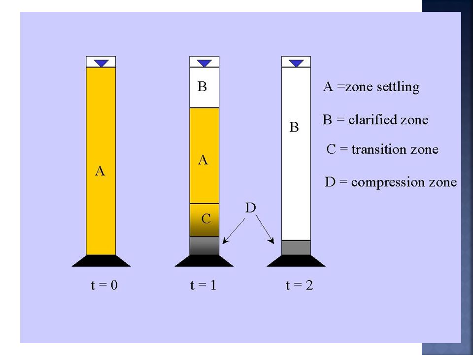
The mechanism of settling may be best described batch settling test in a glass cylinder. Below figure gives a series of observations of batch settling test.

8
figure Shows a cylinder containing a newly prepared slurry of a uniform concentration of uniform solid particles throughout. Various zones of concentration then are established as shown in figure. The heavier faster settling particles settled at the bottom of a glass cylinder are indicated by zone D. Above zone D forms another layer, called zone C, a region of variable size distribution & non uniform concentration. The boundary b/w C & D is usually obscure & is marked by vertical channels through which fluid is rising from the lower zone D as it compresses. Above zone C is zone B, which is a zone of uniform concentration, of approximately, the same conc. As that of the original pulp. Above zone B is zone A, which is a zone of clear liquid. If the original slurry is closely sized with respect to smallest particles, the boundary b/w A & B is sharp.

9
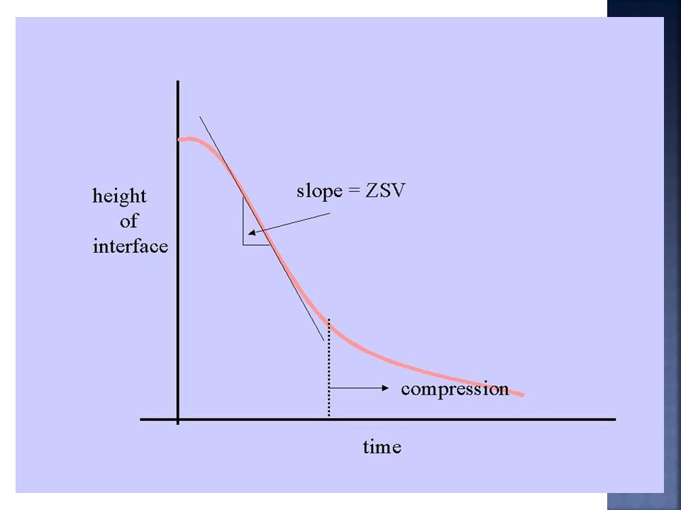
The height of the interface (between the clarified zone and the zone settling zone) versus time is plotted in the figure below to determine the "zone settling velocity" (ZSV). Velocity of this interface is steady after some induction period but changes with time as compression begins. The slope of the steady interface subsidence rate represents zone settling velocity.

11
Initial suspended solids concentration has a significant effect on the ZSV because the higher the suspended solids concentration the more difficult it is to pass water through the pore spaces in the settling matrix. (The only way a matrix can settle is if the water below it is allowed to pass upward through the matrix).
..")
12
1.Suspended solids concentration 2.Depth of settling column (or tank) 3.Stirring ( 0.5 – 2 rpm to prevent “arching”) 4.Temperature 5.Polymer addition ( affects matrix structure)
 3.Stirring ( 0.5 – 2 rpm to prevent arching ) 4.Temperature 5.Polymer addition ( affects matrix structure)")
13
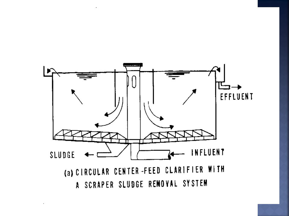
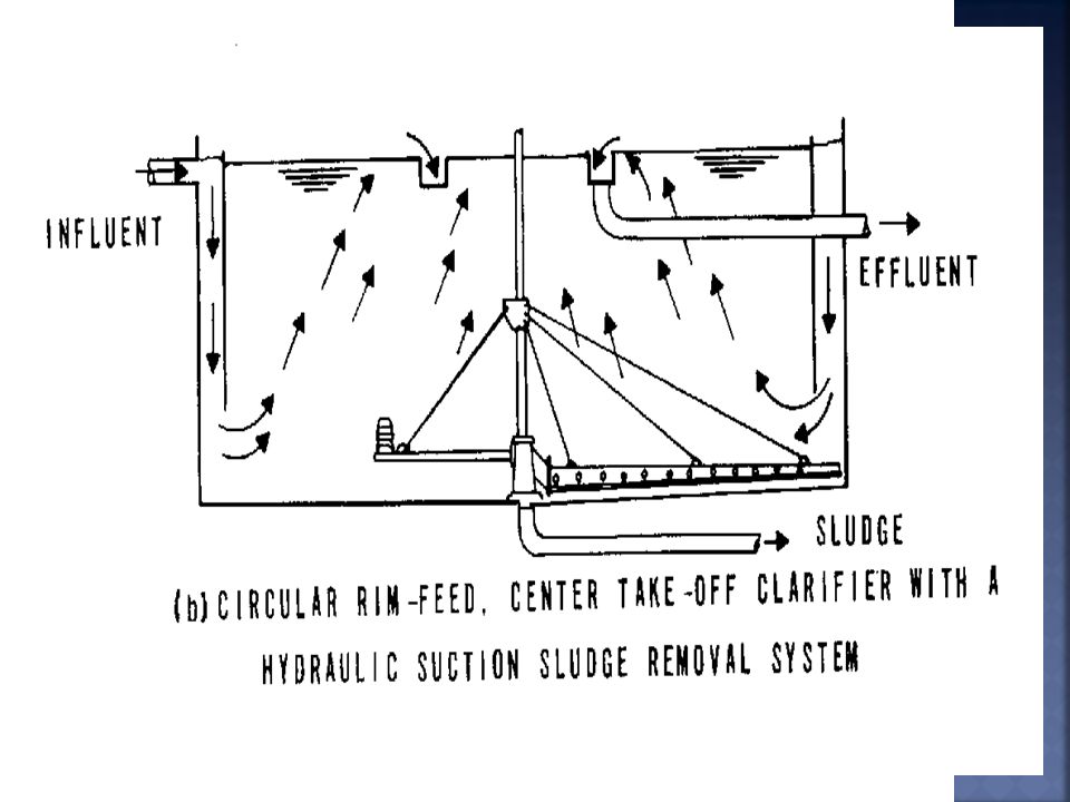
Clarifier: C larifier are used to remove small amounts of solids to produce sparking clear liquids.It is also called as deep bed filters. Thickeners: Industrially, the sedimentation operation may be carried out batch wise or continuously in equipment called thickener. A thickener consists of a relatively shallow tank from the top of which clear liquid is taken off & the thickened liquid is removed from bottom.

14
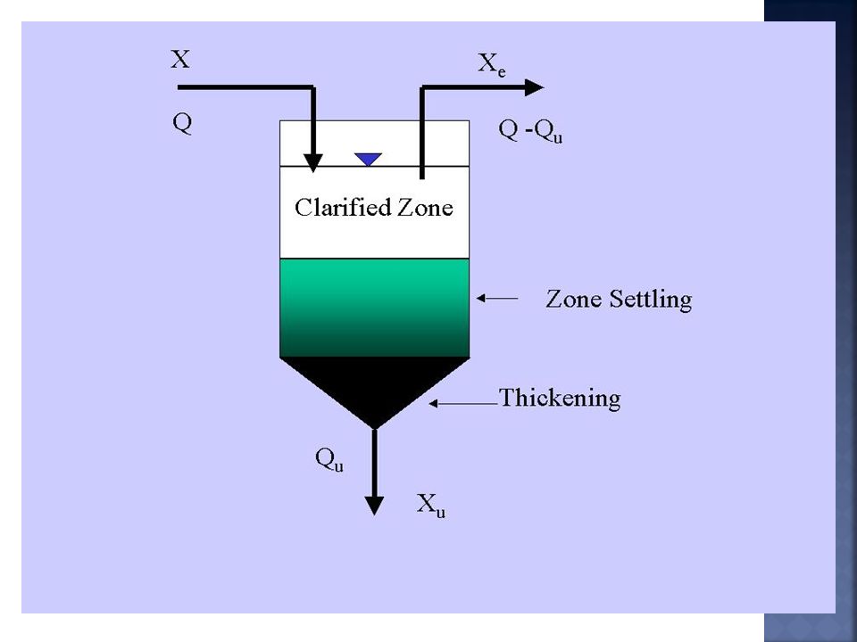
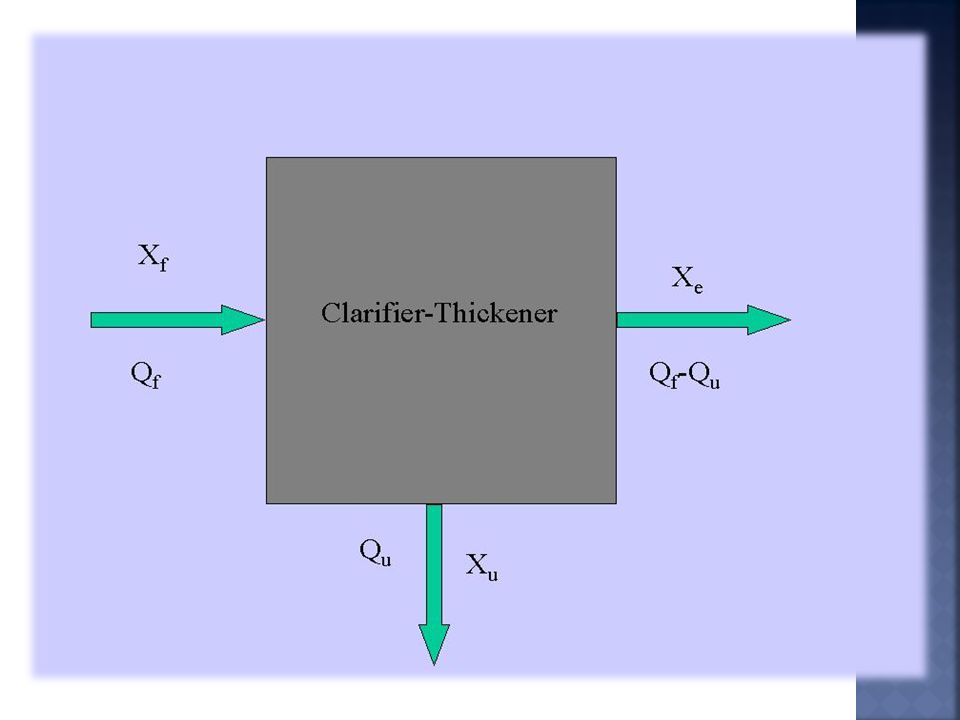
Two important functions of these sedimentation tanks are : clarification and thickening. For a continuous flow clarifier, operated at steady state, mass flow of suspended solids can schematically represented as follows:

17
X = influent suspended solids concentration X e = effluent suspended solids concentration (often close to zero) X u = underflow (thickened) suspended solids concentration. Q = influent volumetric flow rate Q u = underflow volumetric flow rate

18
1) To produce clear liquid, and 2) To produce a given degree of thickening of the suspension. The upward velocity of the liquid must, all the times, be less than settling velocity of particles for production of clarified liquid. Thus, for a given throughout, the diameter of the tank determines the clarifying capacity of the thickener. The thickening of the sludge is controlled by the time of residence of the particles in the tank, & hence, by the depth below the feed inlet.

22
Thank You

Similar presentations


>")


 Introduction.>")


. The separation of solids from fluids (dewatering) is one of the important subjects in the field of mineral dressing Water.>")


.>")


