Download presentation
Presentation is loading. Please wait.

1
HCAL Fall meeting, Nov 11-13,`04 HCAL digital optic link and trigger mapping Ianos Schmidt The university of Iowa

2
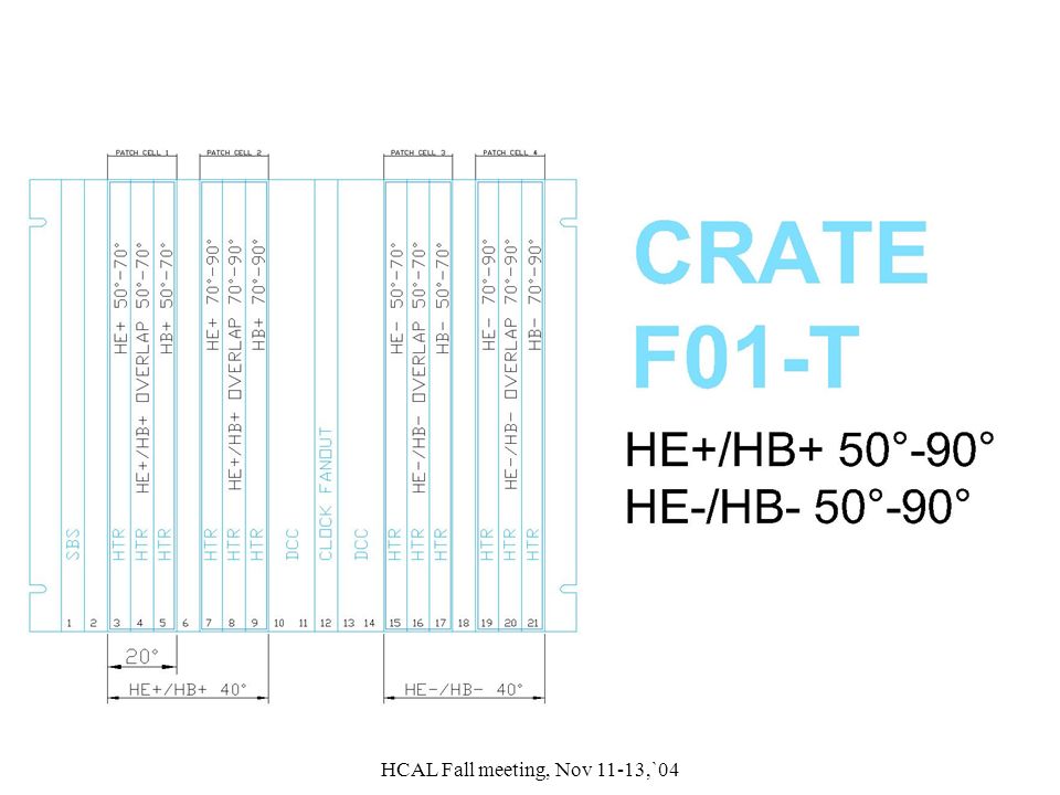
HCAL Fall meeting, Nov 11-13,`04 HCAL HTR crates to RTC crates mapping

3
HCAL Fall meeting, Nov 11-13,`04 Detector view of HB/HE to RTC mapping

4
HCAL Fall meeting, Nov 11-13,`04 Layout of HCAL HTR racks in row F on the second floor of USC55 L M SL L S SS M MM HE “Far side” fibers must reach to here (Fibers from RBX #’s 4 to 9) HE “middle” fibers must reach to here (Fibers from RBX #’s 1 to 3 and 10 to 12) HE “near side” fibers must reach to here (Fibers from RBX #’s 13 to 18)
 HE middle fibers must reach to here (Fibers from RBX #’s 1 to 3 and 10 to 12) HE near side fibers must reach to here (Fibers from RBX #’s 13 to 18)")
5
HCAL Fall meeting, Nov 11-13,`04 Cable length database table for HE(-) on-detector Digital optic cables Medium Long Short Medium General safety contingency 1.0m Longest “long” cable 23.1m Longest “medium” cable 20.2m Longest “short” cable 17.3m Delta = 2.9m
 on-detector Digital optic cables Medium Long Short Medium General safety contingency 1.0m Longest long cable 23.1m Longest medium cable 20.2m Longest short cable 17.3m Delta = 2.9m")
6
HCAL Fall meeting, Nov 11-13,`04

8
Tower Mapping for HE RM2, 3 QIE Ch.# HE Tower Card1 Card2 Card3 0 17 27f 19r 1 16 27m 20f 2 25f 29m 21r 3 25r 23f 21f 4 18f 27r 19f 518r 23r 20r f – front section; m – middle section; r – rear section Tower Mapping for HB QIE Ch.# HB Tower Card1 Card2 Card3 0 16r 10 11 1 15r 6 7 2 14 2 3 3 16f 12 9 4 15f 8 5 5 13 4 1 Tower Mapping for HE RM1, 4 QIE Ch.# HE Tower Card1 Card2 Card3 0 17 28f 19r 1 16 28m 20f 2 26f 29f 22r 3 26r 24f 22f 4 18f 28r 19f 5 18r 24r 20r

9
HCAL Fall meeting, Nov 11-13,`04

10
Detector view of HF mapping

11
HCAL Fall meeting, Nov 11-13,`04

12
HF HTR crates

13
HCAL Fall meeting, Nov 11-13,`04 HO? HO crates are divided into 90 degree segments, with each RM covering 15 degrees. A 90 degree slice across all HO rings requires 13.5 HTR’s. There are many possible ways to map RM fibers to HTR’s. Are there any patterns such as muon triggers… that require a particular mapping of HO signals?

14
HCAL Fall meeting, Nov 11-13,`04 Detector view of HO (rings -1 & -2)
")
15
HCAL Fall meeting, Nov 11-13,`04 Calibration module readout fibers and HTR’s There are at least three options for organizing the calibration readout. 1.keep Calibration readout in time with signal readout. –Results in having many half used HTR’s 2.Have calibration HTR’s in the crates with associated RBX signal HTR’s. –Calibration readout will be delayed in relation to signal. –Patching is not “modular”, best solved by dedicated calibration patch panel. –6 out of 8 fibers would be used in every HTR input. 3.Have all calibration HTR’s in dedicated crate. –Calibration HTR’s would not be on same partition as the associated RBX’s. –HTR’s could be fully utilized.

16
HCAL Fall meeting, Nov 11-13,`04 HB/HE Calibration module readout map option 2.

Similar presentations


 Project Naba K Mondal Tata Institute, Mumbai, India.>")


 PRR Dan Green HCAL Project Manager.>")
 Drew Baden Univ. Of Maryland July 2001.>")


 Conceptual Design (Summary) by Eric.>")

 ● Handling tools ● Deported.>")


