Download presentation
Presentation is loading. Please wait.

1
Chapter 4 Structures for Discrete-Time System Introduction The block diagram representation of the difference equation Basic structures for IIR system Basic structures for IIR system Transposed Forms Basic network structures for FIR systems Basic network structures for FIR systems

2
Introduction Chapter, we will seen the systems described by linear In this Chapter, we will seen the systems described by linear constant-coefficient difference equations can be represented by structures consisting of an interconnection of the basic operations of addition, multiplication by a constant, and delay of addition, multiplication by a constant, and delay Basic operator: (1) Addition operator (2) Multiplication operator (3) Delay operator
 Addition operator (2) Multiplication operator (3) Delay operator")
3
Introduction The system function describe the properties of LTI systems or By making using of the block diagram and signal flow graph descript the computational structures or network for linear time -invariant causal system, the signal flow graph are consist of basic operators.

4
The block diagram representation of the difference equation 1. The block diagram symbols (1)Addition operator (2)Multiplication operator (3)Unit delay operator
Addition operator (2)Multiplication operator (3)Unit delay operator.")
5
(1)Addition operator
Addition operator")
6
(2)Multiplication operator (3)Unit delay operator
Multiplication operator (3)Unit delay operator")
7
The block diagram representation of the difference equation 2. Signal flow graph symbols (1) adder (1) adder (2) multiplier (3) delay
 adder (1) adder (2) multiplier (3) delay.")
8
A signal flow graph is network of directed branches that connect at nodes, or a signal flow graph are consist of the directed branches at nodes, or a signal flow graph are consist of the directed branches and nodes. and nodes.

9
(1)Network nodes :1,2,3,4,5 be denoted w k (n), where k=1,2,3,4,5 (2)Branch (j,k) demotes a branch originating at node(j) and terminating at node(k), with the direction from node(j) to node(k). The types of nodes: Source nodes: which have no entering branches; Sink nodes: which have only entering branches. The magnitude of the node is superimposed every entering branches.

11
Basic structures for IIR system we are concerned with the number of multiplication and delay elements, this is because: delay elements, this is because: First, multiplication is generally a time-consuming and costly operation in digital hardware; Second, a delay element corresponds to memory register; Consequently, the reduction of the number of constant multipliers means an increase of speed, and reduction in the number of delay elements means a reduction in memory requirements

12
Basic structures for IIR system 1. The characters of the IIR filters (or systems) 2. Direct Form-I 3. Direct form II (Canonic direct form) 4. The shortcoming of the direct form 5. Cascade Form 6. Parallel Form
 4. The shortcoming of the direct form 5. Cascade Form 6. Parallel Form.")
13
(1)The impulse response is infinite sequence; (2)the system function have poles which distributed at z-plane; (3)there is a back feed in the structures for IIR system 1.The characters of the IIR filters (or systems)
The impulse response is infinite sequence; (2)the system function have poles which distributed at z-plane; (3)there is a back feed in the structures for IIR system 1.The characters of the IIR filters (or systems)")
14
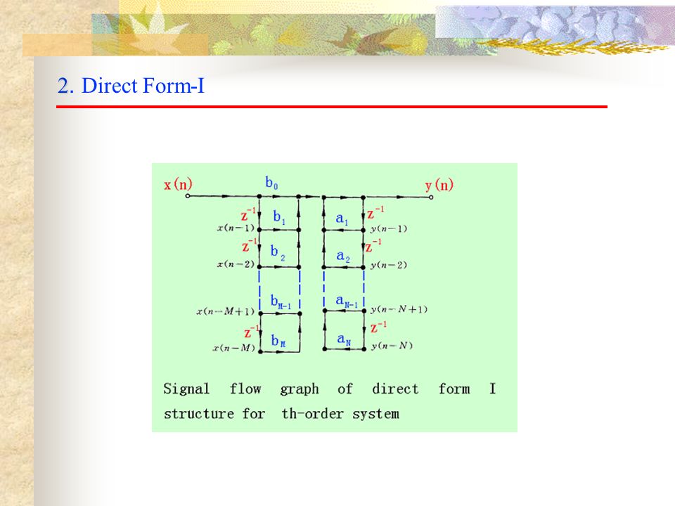
2 2. Direct Form-I

16
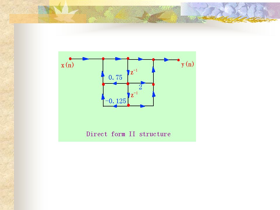
3 3. Direct Form-II(Canonic direct form)
")
17
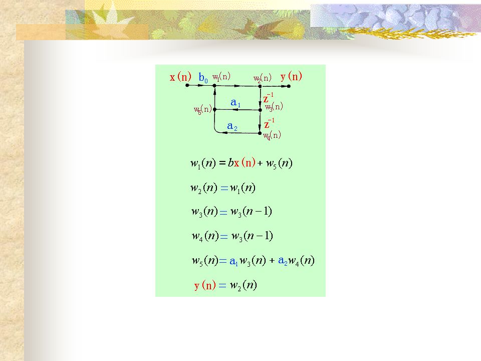
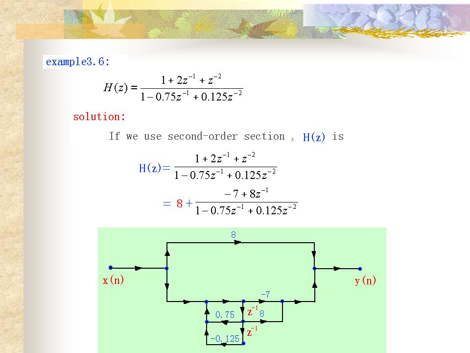
To illustrate the direct form I and direct form II structures, consider the system function Example:

19
4. The shortcoming of the direct form (1)the variation of the coefficients affect effectively the performance of IIR system; ( 2)the performance of IIR system which controlled by the coefficients is not obviousness; ( 2)the performance of IIR system which controlled by the coefficients is not obviousness; This is because the poles and zeros of the IIR system have not directly relation with h,. have not directly relation with h,.
the variation of the coefficients affect effectively the performance of IIR system; ( 2)the performance of IIR system which controlled by the coefficients is not obviousness; ( 2)the performance of IIR system which controlled by the coefficients is not obviousness; This is because the poles and zeros of the IIR system have not directly relation with h,. have not directly relation with h,..")
20
5. Cascade Form

21
6. Parallel Form

24
Parallel form realization for this example with a second-order Since all the poles are real, we can obtain an alternative parallel form realization by expanding H(z) as form realization by expanding H(z) as The resulting parallel form with first-order section is shown as following graph.
 as form realization by expanding H(z) as The resulting parallel form with first-order section is shown as following graph.")
26
Transposed Forms The theory of linear signal flow graphs provides a variety of procedures for transforming signal flow graphs into different forms while leaving the overall system function between input and output unchanged. One of these procedures, called flow graph output unchanged. One of these procedures, called flow graph reversal or transposition, leads to a set of transposed system structures that provide some useful alternative to the structures discussed in the previous section. discussed in the previous section.

27
Transposed Forms Transposition of a flow graph is accomplished by 1.reversing the direction of allbranches in network while 1.reversing the direction of all branches in network while keeping the branch transmittances as they were; keeping the branch transmittances as they were; 2. Reversing the roles of theinput and output so that source 2. Reversing the roles of the input and output so that source nodes become sink nodes and vice versa. nodes become sink nodes and vice versa.

28
Basic network structures for FIR systems The system function of FIR

Similar presentations


![Z-Transform Fourier Transform z-transform. Z-transform operator: The z-transform operator is seen to transform the sequence x[n] into the function X{z},](/17/5301252/big_thumb.jpg "Z-Transform Fourier Transform z-transform. Z-transform operator: The z-transform operator is seen to transform the sequence x[n] into the function X{z},>")


.>")


