Download presentation
Presentation is loading. Please wait.

1
طراحی اتصالات Joints design

2
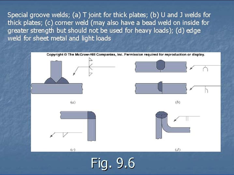
انواع وسائل ايجاد اتصال

3
از اهداف اساسی درديدگاه طراحی برای ساخت کاهش تعداد اتصالات است از اهداف اساسی درديدگاه طراحی برای ساخت کاهش تعداد اتصالات است

25
The Joyce worm-gear screw jack

26
Vehicular screw jack

27
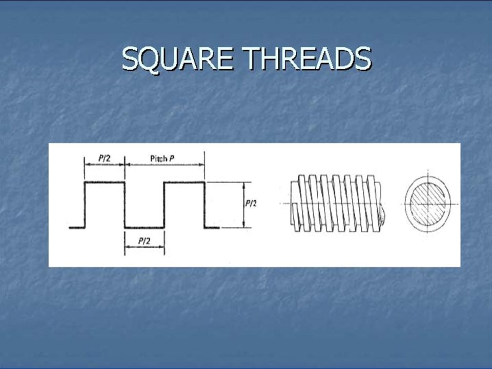
Power screw and nut

29
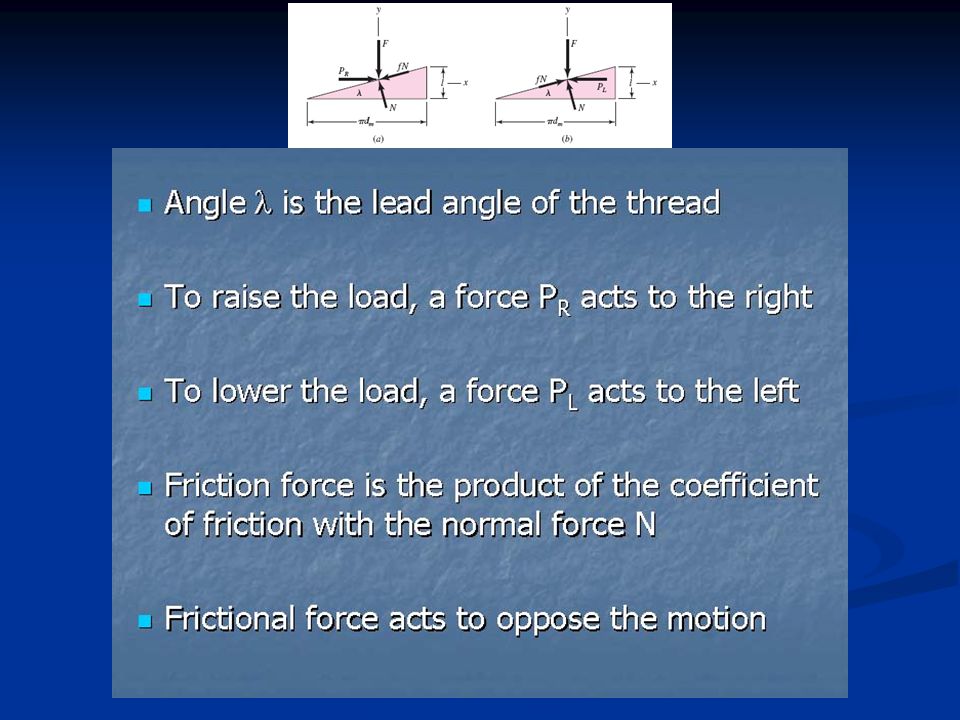
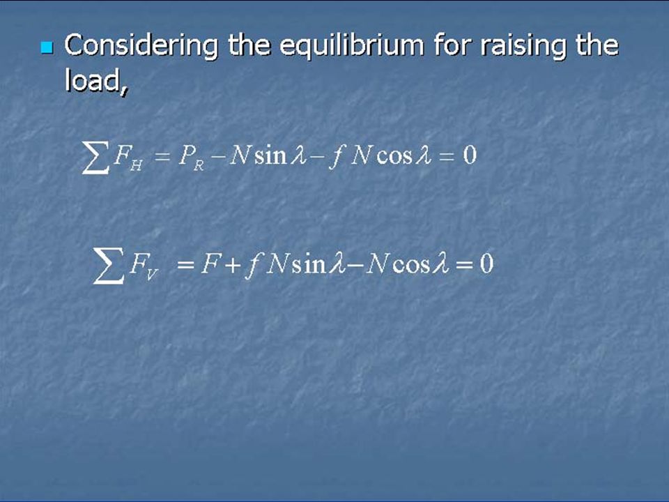
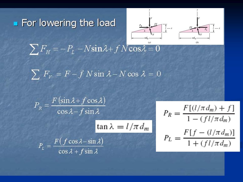
Force diagrams Lifting the loadLowering the load

34
T = P. (d m /2)
")
38
For large collars, the torque should probably be computed in a manner similar to that employed for disk clutches.

39
Screw bearing pressure P b Safe bearing pressures on threads, to protect the moving surfaces from abnormal wear.

40
Coefficients of Friction f for Threaded Pairs

41
Thrust-collar friction coefficient

42
Ham and Ryan showed that the coefficient of friction in screw threads is independent of axial load, practically independent of speed, decreases with heavier lubricants, shows little variation with combinations of materials, and is best for steel on bronze. Sliding coefficients of friction in power screws are about 0.10–0.15.

43
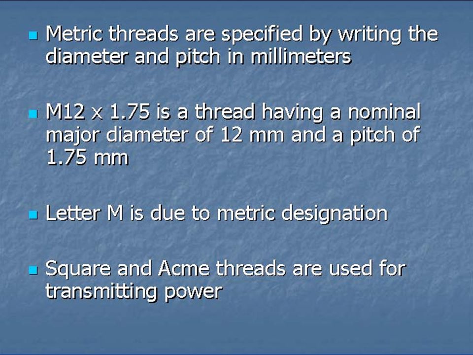
nominal

44
C is constant

50
مثال

51
جواب

52
ادامه جواب

69
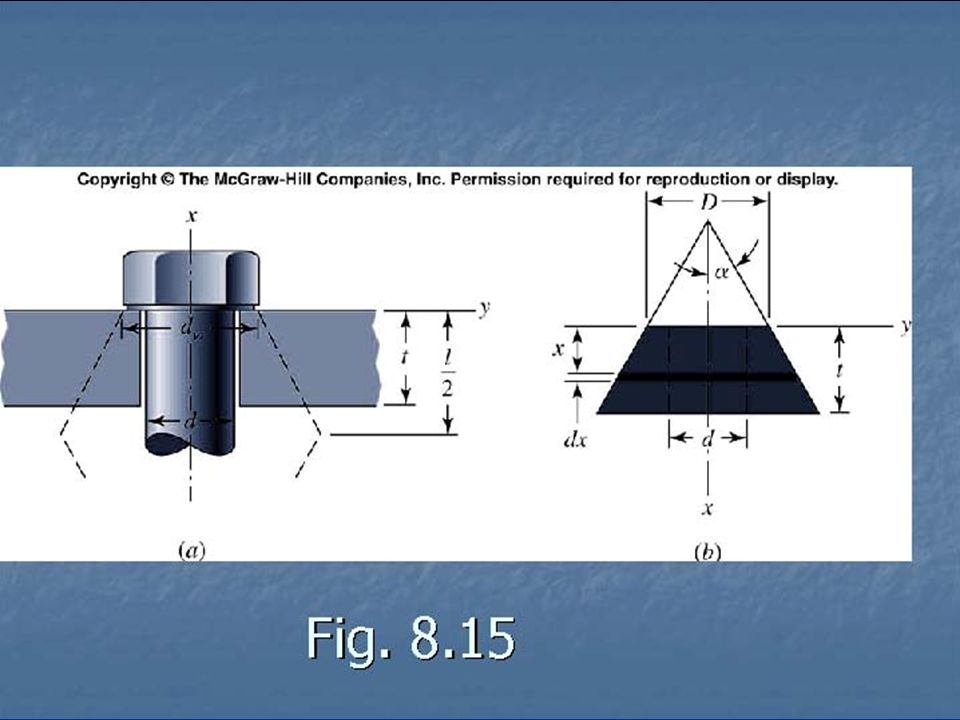
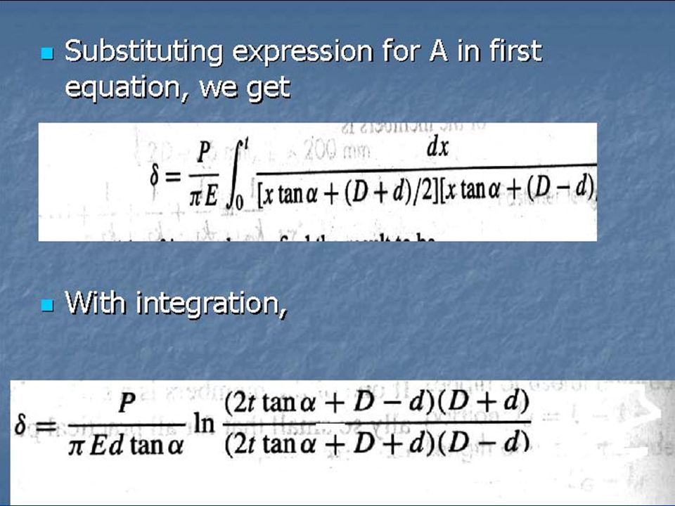
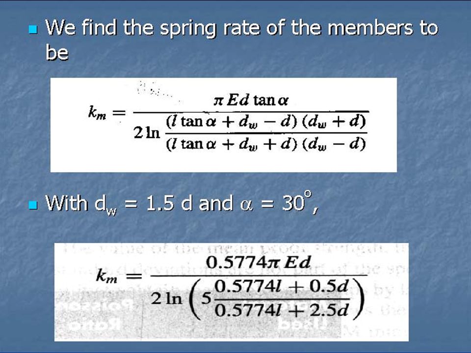
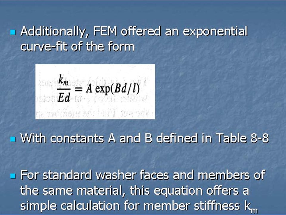
فرآيند محاسبه سفتی پيچها

85
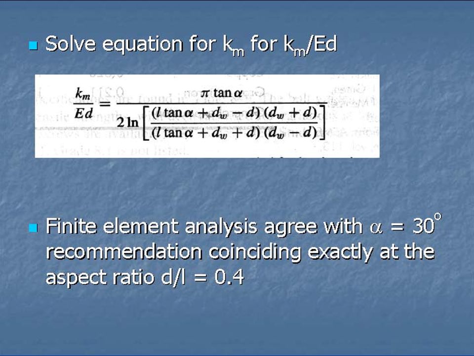
رابطه سفتی و نسبت رعنائی d/l اتصال پيچی

96
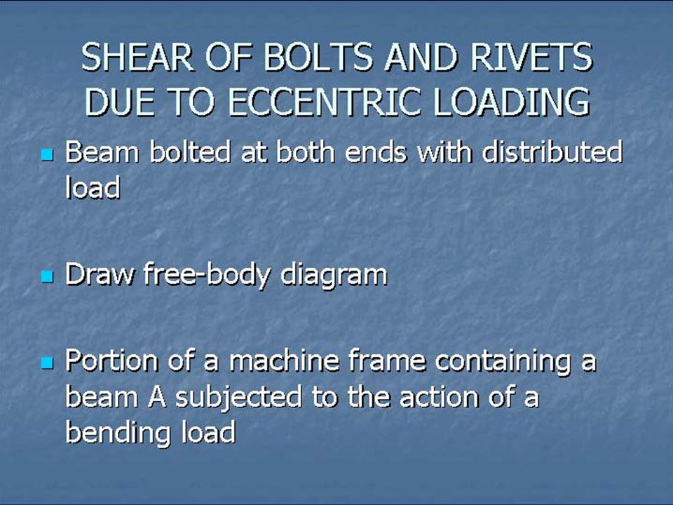
LECTURE # 38

97
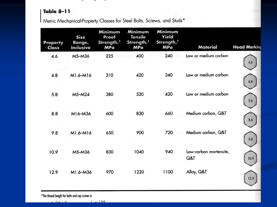
BOLT STRENGTH The strength is specified by stating the minimum proof strength, or minimum proof load, and the minimum tensile strength The strength is specified by stating the minimum proof strength, or minimum proof load, and the minimum tensile strength The proof load is the maximum load (force) that a bolt can withstand without acquiring a permanent set The proof load is the maximum load (force) that a bolt can withstand without acquiring a permanent set
 that a bolt can withstand without acquiring a permanent set The proof load is the maximum load (force) that a bolt can withstand without acquiring a permanent set")
98
The proof strength is the quotient of the proof load and the tensile-stress area The proof strength is the quotient of the proof load and the tensile-stress area The proof strength is about 90 percent of the 0.2 percent offset yield strength The proof strength is about 90 percent of the 0.2 percent offset yield strength ASTM threads are shorter (deals mostly with structures) and generally loaded in shear ASTM threads are shorter (deals mostly with structures) and generally loaded in shear
 and generally loaded in shear ASTM threads are shorter (deals mostly with structures) and generally loaded in shear")
102
TENSION CONNECTIONS-THE EXTERNAL LOAD A clamping force,(preload) F i is applied by tightening the nut before external force, P is applied A clamping force,(preload) F i is applied by tightening the nut before external force, P is applied F i = preload F i = preload P = external tensile load P = external tensile load P b = portion of P taken by bolt P b = portion of P taken by bolt P m = portion of P taken by members P m = portion of P taken by members
 F i is applied by tightening the nut before external force, P is applied A clamping force,(preload) F i is applied by tightening the nut before external force, P is applied F i = preload F i = preload P = external tensile load P = external tensile load P b = portion of P taken by bolt P b = portion of P taken by bolt P m = portion of P taken by members P m = portion of P taken by members")
103
F b = P b + F i = resultant bolt load F b = P b + F i = resultant bolt load F m = P m – F i = resultant load on the members F m = P m – F i = resultant load on the members The load P is tension, and it causes the connection to stretch, or elongate, through some distance The load P is tension, and it causes the connection to stretch, or elongate, through some distance and

104
Since, P = P b + P m Since, P = P b + P m The resultant bolt load is The resultant bolt load is F m < 0

105
Fig. 15.9

106
Fig. 15.10

107
Fig. 15.11

108
F m < 0 These results are valid only as long as some clamping load remains in the members These results are valid only as long as some clamping load remains in the members

110
In all cases, the members take over 80 percent of the external load In all cases, the members take over 80 percent of the external load Making the grip longer causes the members to take an even greater percentage of the external load Making the grip longer causes the members to take an even greater percentage of the external load

111
TORQUE REQUIREMENTS A high preload is very desirable in important bolted connections A high preload is very desirable in important bolted connections If the overall length of the bolt can actually be measured with a micrometer when it is assembled, the bolt elongation due to preload F i can be computed using formula If the overall length of the bolt can actually be measured with a micrometer when it is assembled, the bolt elongation due to preload F i can be computed using formula

112
The nut is simply tightened until the bolt elongates through the distance The nut is simply tightened until the bolt elongates through the distance This ensures that the desired preload has been attained This ensures that the desired preload has been attained The elongation of a screw cannot be measured, because the threaded end is often a blind hole The elongation of a screw cannot be measured, because the threaded end is often a blind hole

113
The torque wrench has a built-in dial which indicates the proper torque The torque wrench has a built-in dial which indicates the proper torque With impact wrenching, the air pressure is adjusted so that the wrench stalls when the proper torque is obtained With impact wrenching, the air pressure is adjusted so that the wrench stalls when the proper torque is obtained Or in some wrenches, the air automatically shuts off at the desired torque Or in some wrenches, the air automatically shuts off at the desired torque

114
The snug-tight condition is the tightness attained by a few impacts of an impact wrench The snug-tight condition is the tightness attained by a few impacts of an impact wrench Or the full effort of a person using an ordinary wrench Or the full effort of a person using an ordinary wrench When the snug-tight condition is attained, all additional turning develops useful tension in the bolt When the snug-tight condition is attained, all additional turning develops useful tension in the bolt

115
Turn-of-the-Nut Method The turn-of-the-nut method is the easiest and least expensive method for installing fasteners with the proper bolt tension. The turn-of-the-nut method is the easiest and least expensive method for installing fasteners with the proper bolt tension. The procedure generally works as follows. An iron worker tightens the bolt and nut as tight as possible using a spud wrench or a pneumatic impact wrench The procedure generally works as follows. An iron worker tightens the bolt and nut as tight as possible using a spud wrench or a pneumatic impact wrench

116
A chalk mark or paint is then made on the bolt and nut A chalk mark or paint is then made on the bolt and nut The bolt is tightened further by either hammering on the spud wrench or using a pneumatic impact wrench until the rotating part has rotated the required amount The bolt is tightened further by either hammering on the spud wrench or using a pneumatic impact wrench until the rotating part has rotated the required amount The paint or chalk mark shows how far the part has rotated and the rotation is always measured relative to the rotation of the bolt. The paint or chalk mark shows how far the part has rotated and the rotation is always measured relative to the rotation of the bolt.

117
The turn-of-the-nut method requires that you compute the fractional number of turns necessary to develop the required preload from the snug- tight condition The turn-of-the-nut method requires that you compute the fractional number of turns necessary to develop the required preload from the snug- tight condition For heavy hexagon structural bolts, the turn-of- th-nut specification states that the nut should be turned a minimum of 180 o from the snug-tight condition under optimum conditions For heavy hexagon structural bolts, the turn-of- th-nut specification states that the nut should be turned a minimum of 180 o from the snug-tight condition under optimum conditions

118
A good estimation of the torque required to produce a given preload is A good estimation of the torque required to produce a given preload is

119
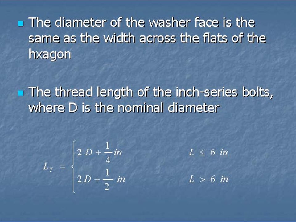
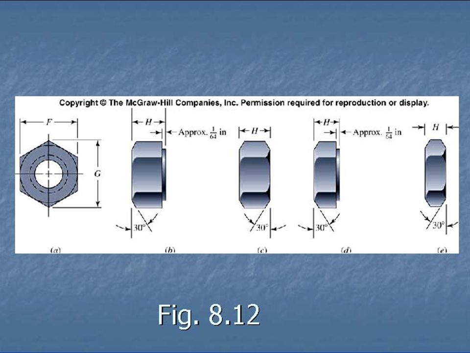
Th diameter of the washer face of a hexagonal nut is the same as the width across flats and equal to 1.5 times the nominal size Th diameter of the washer face of a hexagonal nut is the same as the width across flats and equal to 1.5 times the nominal size d c = (1+1.5d)/2 = 1.25d d c = (1+1.5d)/2 = 1.25d
/2 = 1.25d d c = (1+1.5d)/2 = 1.25d")
120
Define a torque co-efficient K Define a torque co-efficient K T = K F i d T = K F i d The coefficient of friction depends upon the surface smoothness, accuracy, and degree of lubrication The coefficient of friction depends upon the surface smoothness, accuracy, and degree of lubrication

121
On the average, both f and f c are about 0.15 On the average, both f and f c are about 0.15 K = 0.26 for f = f c =0.15 no matter what size bolts are employed and no matter whether the threads are coarse or fine K = 0.26 for f = f c =0.15 no matter what size bolts are employed and no matter whether the threads are coarse or fine

123
BOLT PRELOAD-STATIC LOADING

124
The tensile stress in the bolt can be found by dividing both terms of first equation by the tensile-stress area, A t The tensile stress in the bolt can be found by dividing both terms of first equation by the tensile-stress area, A t The limiting value of b is the proof strength, S b The limiting value of b is the proof strength, S b

125
With the introduction of a load factor n With the introduction of a load factor n Any value of n > 1 ensures that the bolt stress is less than the proof strength Any value of n > 1 ensures that the bolt stress is less than the proof strength

126
JOINT SEPARATION For safe joint, external load be smaller than that needed to cause the joint to separate If separation does not occur, then the entire external load will be imposed on the bolt Let P o be the value of the external load that would cause joint separation

127
Fig. 15.15

128
At separation, F m = 0, At separation, F m = 0, (1 – C)P o – F i =0 (1 – C)P o – F i =0 Let the factor of saftey against joint separation be Let the factor of saftey against joint separation be
P o – F i =0 (1 – C)P o – F i =0 Let the factor of saftey against joint separation be Let the factor of saftey against joint separation be")
129
Fig. 8.18

130
Fig. shows stress-strain diagram of a good quality bolt material Fig. shows stress-strain diagram of a good quality bolt material No clearly defined yield point No clearly defined yield point Fracture at the tensile strength Fracture at the tensile strength No matter how much preload is given to bolt, it will retain its load-carrying capacity No matter how much preload is given to bolt, it will retain its load-carrying capacity

131
The pr-tension is the muscle of the joint and its magnitude is determined by the strength The pr-tension is the muscle of the joint and its magnitude is determined by the strength If the full bolt strength is not used, then money is wasted If the full bolt strength is not used, then money is wasted Good quality bolts can be preloaded into the plastic range to develop more strength Good quality bolts can be preloaded into the plastic range to develop more strength A bolt will either fracture during tightening or not at all A bolt will either fracture during tightening or not at all

132
It is recommended for both static and fatigue loading that the following be used for preload : It is recommended for both static and fatigue loading that the following be used for preload : Where F P is the proof load, obtained from the equation F P = A t S P Where F P is the proof load, obtained from the equation F P = A t S P S P is the proof strength obtained from tables 8-4 to 8-6 S P is the proof strength obtained from tables 8-4 to 8-6

133
For other materials, an approximate value is S P = 0.85 S Y

134
Fig. 8.17

135
Fig. 8.18

136
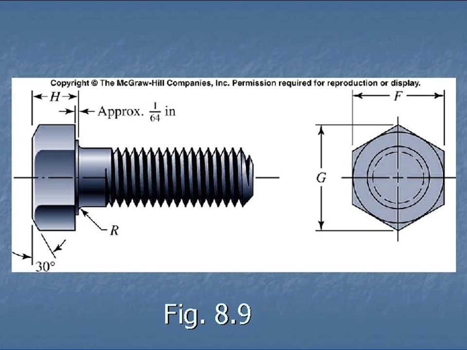
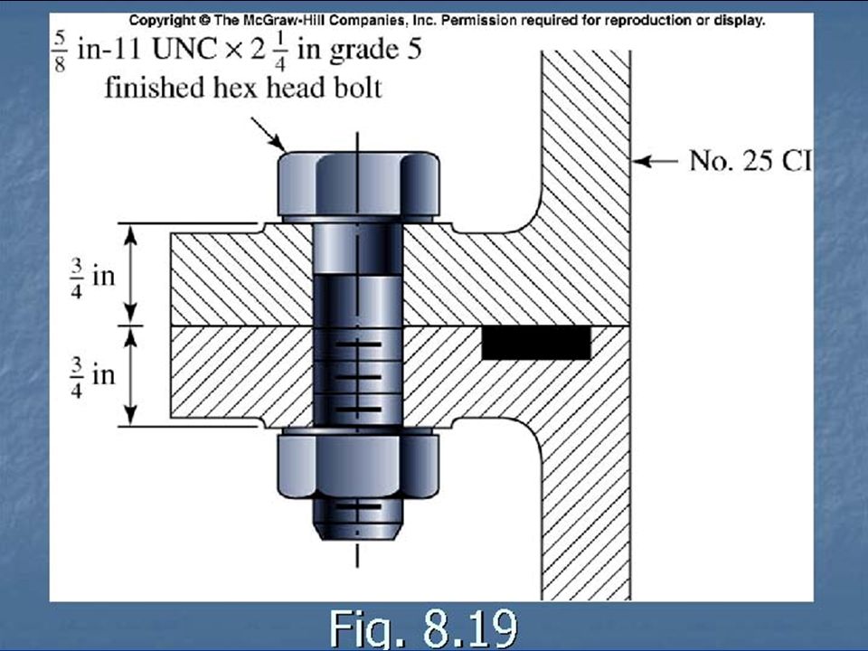
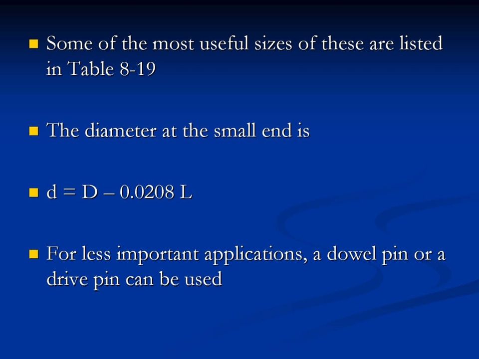
Fig. 8.19

155
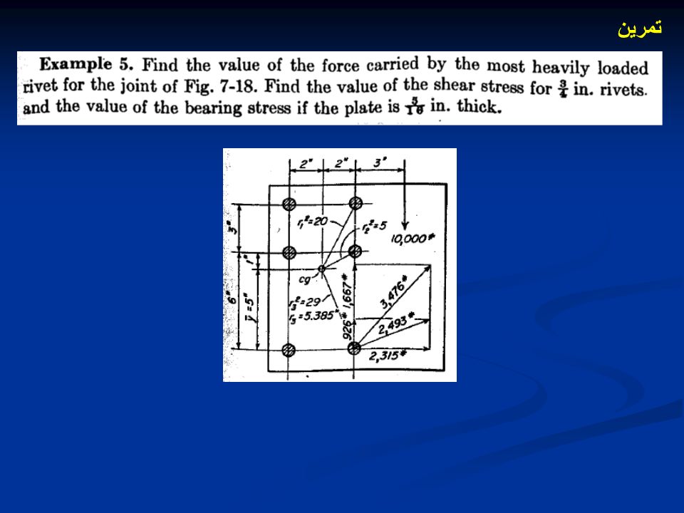
تمرين

Similar presentations


>")


>")


