Download presentation
Presentation is loading. Please wait.

1
Diesel Engine Management Systems Steve Baker

2
Diesel Engine Management Systems Steve Baker

3
Basic Diesel Fuel Delivery System 1. Fuel Return Line 2. Fuel Injection Pump 3. Injectors 4. Fuel Filter 5. Fuel Tank 6. Swirl Pot 7. Fuel Feed Line Low Pressure High Pressure Spill Return

4
Air Intake System

5
Engine Management Systems L- Series 2.0 Litre EDC 15 M47R 2.0 Litre DDE4

6
Advantages of EDC Greater Fuel Economy Reduced Exhaust Emissions Reduced Engine Noise More Effective Cold Starting Smoother Engine Operation

7
Electronic Control Module (ECM)
")
8
EDC 15 System Inputs

9
Crankshaft Position Sensor (CKP)
")
10
Injector Needle Lift Sensor

11
Coolant Temperature Sensor (ECT) Cº
 Cº ")
12
Manifold Absolute Pressure Sensor (MAP)
")
13
Throttle Potentiometer

14
Brake Pedal Switch

15
Inlet Air Temperature/Mass Air Flow Sensor (IAT/MAF)
")
16
Immobilisation Signal

17
Vehicle Speed Sensor

18
Inputs Ignition Switch Air Con Request

19
Inputs Trinary Switch Evaporator Temperature Sensor

20
System Outputs

21
Glow Plug

22
Malfunction Indicator Lamp (MIL)
")
23
Air Conditioning Compressor Switching Input ComponentOffOn Accelerator Pedal Position Sensor Above 85 Below 80 ECT Sensor 118 c (244 f)112 c (234 f) A/C Pressure Sensor Low Limit High Limit 1.6 Bar(23.2psi) 29 Bar (421 psi) 2.0 Bar (29 psi) 23 Bar (334 psi)
112 c (234 f) A/C Pressure Sensor Low Limit High Limit 1.6 Bar(23.2psi) 29 Bar (421 psi) 2.0 Bar (29 psi) 23 Bar (334 psi)")
24
Cooling Fan Switching Input Component Fan Speed OnOff ECT Sensor: A/C Models Non A/C Models Low High 104°c(219°) 112°c(234°) 104°c(219°) 98°c (208°f) 106°c (223°f) 98°c (208°f) A/C SwitchLowWith Switch A/C Pressure Sensor High19 Bar (275 psi) 14 Bar (203psi)
 112°c(234°) 104°c(219°) 98°c (208°f) 106°c (223°f) 98°c (208°f) A/C SwitchLowWith Switch A/C Pressure Sensor High19 Bar (275 psi) 14 Bar (203psi)")
25
1.Fuel Inlet 2.Fuel Outlet (Spill) 3.Timing Device Plunger Fuel Injection Pump
 3.Timing Device Plunger Fuel Injection Pump")
26
4.ECU (micro controller) 5.Axial Piston 6.Distributor Sleeve 7.Hydraulic Head 8.Fuel Quantity Solenoid Valve 9.Outlet to Fuel Injector 10.Non Return Valve 11.Timing Device Solenoid Fuel Injection Pump
 5.Axial Piston 6.Distributor Sleeve 7.Hydraulic Head 8.Fuel Quantity Solenoid Valve 9.Outlet to Fuel Injector 10.Non Return Valve 11.Timing Device Solenoid Fuel Injection Pump")
27
12. Timing Device Solenoid Valve 13. Intermediate Chamber 14. Cam Plate 15. Timing Ring 16. Toothed Wheel 17. Supply Pump 18. Drive Pulley 19. Drive Plate

28
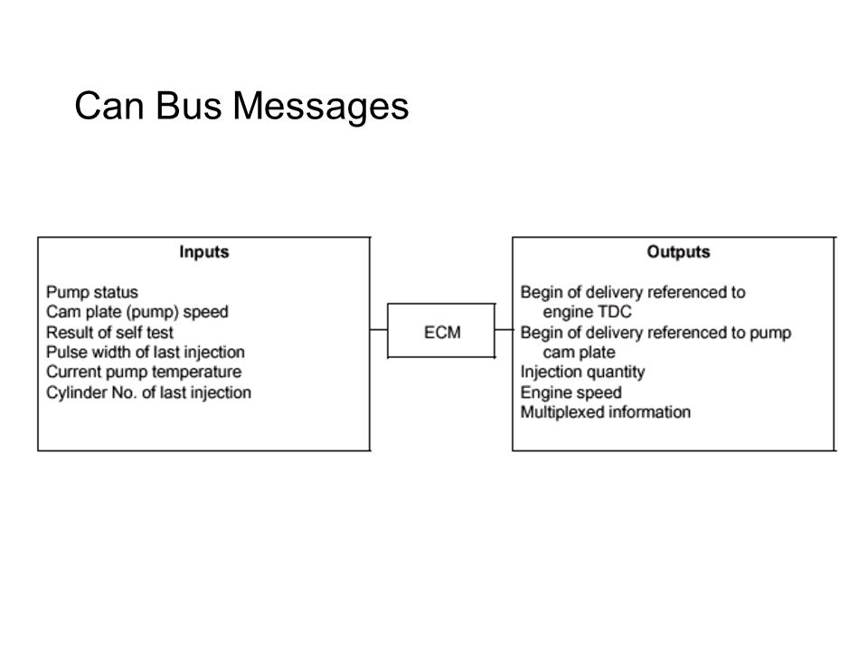
Can Bus Messages

31
Exhaust Gas Recirculation

32
ROVER 25 EDC15M ECM OVERVIEW

33
ROVER 25 EDC15M ECM FUELING

34
ROVER 25 EDC15M ECM DRIVER DEMAND SENSORS

35
ROVER25 EDC15M ECM INPUTS/OUTPUTS

36
DDE 4

37
What Is Common Rail Injection? A System Where All Injectors Are Fed Via a Shared Fuel Line First Developed by Elasis in Italy First Prototype System in 1993 Idea Bought & Developed by Bosch

38
Advantages of Common Rail Injection Fuel Injected at the Exact Time Required Precise Metering of Fuel Required Constant High Fuel Pressures Optimised Fuel Consumption

39
Advantages of Common Rail Injection Reduced Emissions Very Smooth Engine Operation Allows Two Stage Injection

40
Injection Characteristics Standard Common Rail

41
Fuel Delivery System

42
Fuel Delivery Schematic 1.Pressure Sensor and Fuel Filter 2.Pressure Relief Valve 3.High Pressure Injection Pump 4.In Line Electric Fuel Pump (Medium Pressure) 5.Bi-metallic By-pass Valve 6.Fuel Cooler 7.Fuel Pump
 5.Bi-metallic By-pass Valve 6.Fuel Cooler 7.Fuel Pump")
43
Low Pressure Pump

44
High Pressure Pump

46
System Inputs

47
Crankshaft Position Sensor

48
Camshaft Sensor

49
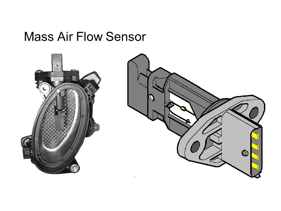
Mass Air Flow Sensor

51
Pedal Demand Sensor

53
Coolant Temperature Sensor (ECT) Cº V
 Cº V")
54
Coolant Temperature Sensor (ECT) Cº V
 Cº V")
55
Low Pressure Sensor

56
High Pressure Sensor

57
Boost Pressure Sensor Pedal Switches

59
Immobilisation (EWS3)
")
60
Automatic Gearbox

62
System Outputs

64
Outputs Fuel Pump Relay Main Relay Air Con Relay Cooling Fan Relay

65
Outputs Fuel Pump Relay Main Relay Air Con Relays

66
Outputs Fuel Pump Relay Main Relay Air Con Relay Cooling Fan Relay

67
Fuel Pressure Regulator

68
Glow Plug ECU

69
Glow Plug Pre-heat Seconds Degrees Celsius

70
Injectors

72
Injectors Closed

73
Injectors Open

74
Injectors

75
Exhaust Gas Recirculation

76
Cruise Control Component Layout

77
Cruise Control Control Diagram

78
Cruise control

80
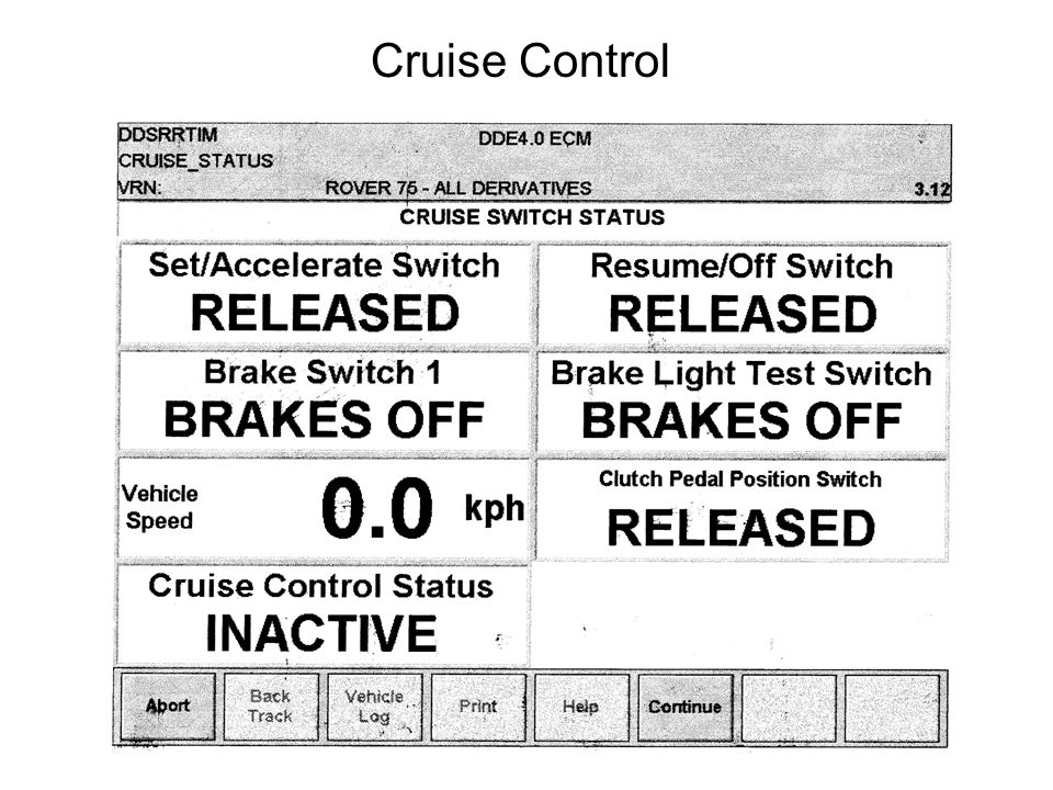
Cruise Control

81
Testbook Real Time Display

82
Engine Roughness

83
Engine Roughness Fuel Correction

84
Pedal Demand Sensors

85
Cruise Control

Similar presentations


 IGNITION SYSTEM DISTRIBUTORLESS IGNITION SYSTEM.>")


>")


.>")


